US3772687A - Electrically-controlled alarm system - Google Patents
Electrically-controlled alarm system Download PDFInfo
- Publication number
- US3772687A US3772687A US00224732A US3772687DA US3772687A US 3772687 A US3772687 A US 3772687A US 00224732 A US00224732 A US 00224732A US 3772687D A US3772687D A US 3772687DA US 3772687 A US3772687 A US 3772687A
- Authority
- US
- United States
- Prior art keywords
- valve
- signal
- electrical
- providing
- disclosed
- Prior art date
- Legal status (The legal status is an assumption and is not a legal conclusion. Google has not performed a legal analysis and makes no representation as to the accuracy of the status listed.)
- Expired - Lifetime
Links
Images
Classifications
-
- G—PHYSICS
- G08—SIGNALLING
- G08B—SIGNALLING SYSTEMS, e.g. PERSONAL CALLING SYSTEMS; ORDER TELEGRAPHS; ALARM SYSTEMS
- G08B25/00—Alarm systems in which the location of the alarm condition is signalled to a central station, e.g. fire or police telegraphic systems
- G08B25/01—Alarm systems in which the location of the alarm condition is signalled to a central station, e.g. fire or police telegraphic systems characterised by the transmission medium
- G08B25/012—Alarm systems in which the location of the alarm condition is signalled to a central station, e.g. fire or police telegraphic systems characterised by the transmission medium using recorded signals, e.g. speech
-
- G—PHYSICS
- G08—SIGNALLING
- G08B—SIGNALLING SYSTEMS, e.g. PERSONAL CALLING SYSTEMS; ORDER TELEGRAPHS; ALARM SYSTEMS
- G08B3/00—Audible signalling systems, e.g. audible personal calling systems
- G08B3/06—Audible signalling systems, e.g. audible personal calling systems using hydraulic transmission; using pneumatic transmission
Definitions
- ABSTRACT [22] Filed: Feb. 9, 1972 An alarm system is disclosed for providing an audible [21] Appl. No.: 224,732
- a trigger circuit is 521 U.S. c1 340/404, 116/112, 340/224, actuated y a receiver and a remotely located trans- 340/329, 343/225 mitter, to initiate operation, which in the disclosed 51 Int. Cl. G08b 3/06 embodiments involves a compound Pattern or Cycle [58] Field of Search 340/224, 385, 388, for more effective use Of the fluid and to increase the 340 404 329; 343 225; 1 1 2 03 severity of the signal as human stimulus. As disclosed,
- the system also incorporates heater means for main- [56] References Ci taining the pressure structure operative over an ex- UNITED PATENTS tended interval of time.
- the present invention contemplates an alarm system utilizing fluid under pressure to actuate a horn under the control of an electrical system and a solenoid valve structure.
- the electrical system incorporates a trigger circuit means for initiating operation upon the occurrence of an intruder signal which may be provided from a remote location by a radio transmitter operating a receiver in the proximity of the alarm unit.
- the electrical system also incorporates oscillation means to provide cyclic or compound cyclic operating patterns serving to conserve the power fluid for most effective operation as well as increasing the effectiveness of the signal as a human stimulus.
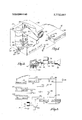
- FIG. 1 is a perspective view of an apparatus in accordance with the present invention fragmentarily sectioned to illustrate certain components therein;
- FIG. 2 is a partly sectioned elevational view. ofa component part of the system of FIG. 1;
- FIG. 3 is a schematic and block diagram of the electrical structure embodied in the system of FIG. 1.
- the alarm system is depicted to include two remotely located units, specifically, a transmitter 12 and an alarm unit 14 (incorporating a receiver).
- the transmitter 12 may comprise any of a variety of conventional self-contained radio transmitters for providing a signal to a receiver (not shown in FIG. ll) located within an electrical package 16 for completing an electrical circuit, e.g., providing a switch closure.
- the transmitter 12 and the cooperative radio receiver provided in the electrical package 16 may comprise FSK (frequency shift keyed) units as well known in the prior art.
- the electrical package 16 actuates a solenoid valve 18 in a cyclic operating pattern.
- the valve 18 is connected between a pressure vessel 20 and a gas-operated horn 22 as described in detail below.
- the alarm unit 14 provides an effective sonic human stimulus which endures for a substantial interval.
- the transmitter 12 may be embodied in a relatively small housing 24 which may be conveniently carried by a person.
- a push button 26 is incorporated in the transmitter 12 for actuating the device to command the operation of the alarm unit 14. Accordingly, a person, having control of the transmitter 12, may simply depress the button 26 as for example from any location in a home, to actuate the alarm unit 14 for providing an effective alarm signal.
- an electrical receptacle 28 is provided in the housing 24 whereby the transmitter 12 may be connected to any of a variety of switching structures. Specifically, for example, window, door, light-actuated or other switches may be connected to the transmitter 12 through the receptacle 28 to automatically actuate the transmitter and thereby activate the alarm unit 14.
- the alarm unit 14 While the transmitter 12 is portable to the extent of being convenient to personally carry, the alarm unit 14 will normally be somewhat-permanently installed. Usually, although not necessarily, the alarm unit 14 will be located adjacent to a source of alternating-current power which is provided to the unit 14 through a cord I 30. As indicated, such power is not required and in that regard, the unit 14 incorporates a battery pack (in the electrical package 16) as disclosed in detail below.
- the housing 32 contains the electrical package 16 as indicated above, which may be fixed in position and may include the battery pack and the electrical control system as well as the receiver, as considered in detail below.
- An electrical cable 34, from the electrical package 16 extends to the solenoid valve 18 which is pneumatically connected between a pressure vessel fitting 38 and the horn 22.
- the solenoid valve 18 for example may comprise an integral unit as commercially available, incorporating a valve and actuating-coil structure.
- the pressure vessel fitting 38 provides pneumatic connection into the communication vessel 20 and will be considered in greater detail below.
- the vessel 20 may take a variety of forms, specifically including a commerically available can containing fluid (Freon) under pressure and for releasing the fluid in a gaseous form, under control of a pinactuated valve constructed within the pressure vessel 20.
- an electrical heater is incorporated for maintaining the pressure vessel 20 above the freezing temperature.
- a pair of electrical-resistance heating bands 40 and 42 extend about the cylindrical surface of the vessel 20, and are held in position by electrically insulating fasteners 44.
- Electrical cables 46 couple the bands 40 and 42 to the electrical package 16 from which the bands are energized during an interval when the alarm unit is operated.
- the bands 40 and 42 comprise resistors for converting electrical energy into heat to maintain the temperature of the vessel 20 above freezing. Separate bands 40 and 42 are provided for the separate utilization of direct current and alternating current energy as described in detail below.
- the transmitter 12 may either be carried by an individual for conveniently providing an alarm or may be connected to an auxiliary switch structure (not shown) by the utilization of the receptacle 28.
- the alarm unit 14 will be somewhat-more permanently installed in a convenient obscure location.
- the cord 30 will be connected to a source of alternating-current energy whereby the battery pack is maintained and alternating-current drive power is provided.
- the alarm unit 14 may be employed to accomplish other signals. Specifically, a receptacle 50 in a panel 51 is connected through a cable 52 to the electrical package 16.
- the receptacle 50 provides a closed circuit at a time when the alarm unit is active. Accordingly, a light or various other signal structures may be connected to the receptacle 50 for energization concurrently with the operation of the alarm unit, as explained in detail below.
- the electrical package 16 Upon actuation by the transmitter 12, the electrical package 16 passes from its quiescent state to accomplish a number of operations. Specifically, the electrical package 16 actuates the solenoid valve 18 through the cable 34 permitting the passage of fluid (normally in a gaseous form) from the pressure vessel 20 to drive the horn 22. As described in detail, the valve 18 is operated in a cyclic pattern to maintain an effective human stimulus and/or conserve fluid from the vessel 20.
- the electrical package 16 also provides both alternating-current and directcurrent energy to the heating bands 40 and 42 which in turn maintain the temperature of the pressure vessel above the freezing level. Still further, as indicated above, the electrical package 16 also provides a closed circuit at the receptacle 50 as to operate a light or other signal apparatus.
- the alarm unit 14 In the event that the alarm unit 14 is isolated from alternating-current power (for any reason) the unit continues to remain fully operative powered by the battery pack incorporated in the electrical package 16 as considered in detail below.
- the key 54 is matingly received in a lock switch 56 (panel 51) which is connected to the electrical package 16 through the cable 52. As described in detail below, actuation of the lock switch 56 by the key 54 resets the unit to quiescent state.
- the pressure vessel fitting 38 receives the pressure vessel 20 and is connected through a duct 58 to the solenoid valve 18 which is in turn connected through a duct 60 to the horn 22.
- the fitting 38 may be machined, cast or otherwise formed to provide a chamber 62 for communication with the vessel 20.
- a valve-actuating pin 64 is seated in a bore 66 within the fitting 38 for opening the mating valve within the pressure vessel 20.
- a passage 67 extends from the space 62 to a normally extending passage 68 which threadably receives the duct 58.
- the opposed end of the duct 58 is threadably received in the valve portion 70 of the solenoid valve 18 for communication through the duct 60 to the horn 22.
- the solenoid valve 18, as previously indicated, incorporates an operating coil 72.
- FIG. 3 illustrating the transmitter l2 and the components of the electrical package 16 in detail along with the other electrical components.
- the receiver 80 upon actuation by the transmitter 12, provides the closure of a switch 82 (indicated in phantom).
- the receiver is powered by a battery pack 84 which is connected in a loop with a.c. input terminals 86, a limiting resistor 88 and a rectifier 90. Consequently, alternating (rectified) and direct power sources are connected in parallel to drive the receiver and additionally to supply power through a controlled rectifier 92 (SCR) and the normally closed lock switch 56 to a power bus 94.
- SCR controlled rectifier 92
- the controlled rectifier 92 receives a switching input through a resistor 96 from the switch 82. Accordingly, upon closure of the switch 82, the controlled rectifier 92 becomes conductive and continues to conduct until the lock switch 56 is opened to interrupt the flow of current to the bus 94.
- the bus 94 Upon being energized, the bus 94 in turn energizes the solenoid valve 18 (symbolically represented) and the similarly represented d.c. heater 98 and the a.c. heater 100 (embodying the bands 40 and 42 (FIG. 1)).
- the solenoid valve 18 is energized in a cyclic manner as by the operation of a pair of multivibrators 102 and 104 which function to control a power transistor 106. Alternate modes are provided for the operation of the system, depending upon whether a control switch 108 is open or closed.
- the function of the multivibrators 102 and 104 in the control system is to cycle the operation of the alarm in two specific aspects: (1) to accomplish a psychological effect in accordance with normal human senses of perception and (2) to increase the interval of operation by the conservation of the pressurized gas drawn from the source.
- the alarm may be provided for a prolonged interval by a cycle which is audibly presented as a dis-continuous sound. For example, it has been found desirable to provide a signal which is on for approximately one-third of a second and of for approximately one-half second in a cyclic pattern. That is, the effectiveness of such a signal is substantially as great as a continuous signal.
- Such cyclic operation is accomplished by the multivibrator 102, during the interval when the switch 108 is open.
- Another aspect of cyclic operation relates to the physiological effect upon the human senses of perception. Specifically, on the application of an intense sound to the human ear, an involuntary reaction rapidly diminishes the sensitivity of the ear somewhat in the fashion of an automatic volume control. However, the reaction is not instantaneous and, accordingly, it has been determined that by providing a cyclic signal of between 45 and 60 cycles per second, the effect is more enduring. It is exceedingly difficult for a person to ignore such a signal.
- the multivibrator 104 operates on a 45 hertz frequency to accomplish the psychological cycle.
- the multivibrators 102 and 104 are free-running units, for example, multivibrator 102 operating on a period of one-half second off and one-third second on.” During the on interval, the multivibrator 104 is operated at a higher frequency, e.g., 45 hertz. As a consequence, the output from the multivibrator 104 applied to the power transistor 106 consists of a burst of 45 hertz pulses which burst has a duration of one-third second. Thereafter, the transistor 106 receives no signal second. The compound cycle is repeated indefinitely.
- the multivibrators 102 and 104 Upon energization of the bus 94, the multivibrators 102 and 104 become cyclically operative to drive the transistor 106 and actuate the solenoid valve 18. Also, the current is supplied to the d.c. heater 98 which embodies the resistance heating band 40 to warm the pressure vessel 20. Additionally, the d.c. power is available at terminals 109 for an external device (receptacle 50, FIG. 1 Finally, the potential in the bus 94 also triggers a controlled rectifier 110 (SCR) thereby providing direct current from the terminals 86 through the a.c. heater 100. Accordingly, the heater 100 (incorporating the band 42) also functions to warm the pressure vessel 20.
- SCR controlled rectifier 110
- the coil 72 opens the valve to provide the flow of gas as described in detail above.
- the cyclic operation of the multivibrators 102 and 104 results in a compound cycle that endures either until the supply of fluid power is exhausted or the unit is switched off by use of the key 54 (FIG. 1).
- the switch 56 may be opened interrupting the primary current through the controlled rectifier 92 which as a consequence stops conduction, until or unless another trigger signal is received from the receiver 80.
- the controlled rectifier 110 operates during half cycles of the applied alternating-current energy and, as a consequence of deenergizing the bus 94, is promptly cut off to halt further energization of the a.c. heater 100.
- the heaters 98 and are effective to maintain the pressure vessel 20 above the freezing" level. Accordingly, the system will continue to operate (unless reset) during a prolonged interval while the vessel 20 is completely exhausted. Thus, the present system is deemed to provide a very effective signal while utilizing an economical and practical structure.
- various embodiments departing from that disclosed herein will be readily apparent to those skilled in the art. Accordingly, the scope hereof is deemed to be in accordance with the claims as set forth below.
- An alarm system comprising:
- a gas-operated warning signal means for providing a perceivable signal
- gas-pressure energy means for providing gas under pressure for actuating said warning signal means; valve means for connecting said energy means to said warning signal means;
- control means for said actuating means to operate said actuating means to open said valve means in a multiple-cycle pattern wherein an operating cycle includes time-spaced operating intervals of less than 5 seconds duration, during which said valve means is opened and closed at a frequency of between 45 and 60 times per second.
- valve means comprises a solenoid-operated valve and said control means comprises an electrical system for providing electrical signals in accordance with said operating cycle.
- control means includes at least one multivibrator means for providing said electrical signals.
- a system according to claim 3 further including manual switch means for controlling the operation of said control means.
Landscapes
- Physics & Mathematics (AREA)
- General Physics & Mathematics (AREA)
- Health & Medical Sciences (AREA)
- Audiology, Speech & Language Pathology (AREA)
- General Health & Medical Sciences (AREA)
- Business, Economics & Management (AREA)
- Emergency Management (AREA)
- Burglar Alarm Systems (AREA)
Abstract
An alarm system is disclosed for providing an audible signal, incorporating a pressurized vessel for supplying fluid to a sonic horn under control of an electrical system and a solenoid valve. As disclosed, the electrical system incorporates independent a.c. and d.c. power arrangements for energizing the valve as well as the remainder of the control system. A trigger circuit is actuated by a receiver and a remotely located transmitter, to initiate operation, which in the disclosed embodiments involves a compound pattern or cycle for more effective use of the fluid and to increase the severity of the signal as human stimulus. As disclosed, the system also incorporates heater means for maintaining the pressure structure operative over an extended interval of time.
Description
O United States Patent [191 [111 3,772,687
Scott Nov. 13, 1973 [5 ELECTRICALLY-CONTROLLED ALARM 3,284,796 11/1966 Borsattino et al 340/384 E SYSTEM [75] Inventor: Angus A. Scott, Palos Verdes Primary Examiner Dvid Trafto" Estates, C lif Attorney-Robert Berliner [73] Assignee: ConsultingSpecialties,Inc.,
Torrance, Calif. [57] ABSTRACT [22] Filed: Feb. 9, 1972 An alarm system is disclosed for providing an audible [21] Appl. No.: 224,732
Related US. Application Data signal, incorporating a pressurized vessel for supplying fluid to a sonic horn under control of an electrical system and a solenoid valve. As disclosed, the electrical system incorporates independent a.c. and d.c. power [63] Continuation-impart of Ser. No. 94,788,- Dec. 3, I
1970, d d, arrangements for energizing the valve as well as the remainder of the control system. A trigger circuit is 521 U.S. c1 340/404, 116/112, 340/224, actuated y a receiver and a remotely located trans- 340/329, 343/225 mitter, to initiate operation, which in the disclosed 51 Int. Cl. G08b 3/06 embodiments involves a compound Pattern or Cycle [58] Field of Search 340/224, 385, 388, for more effective use Of the fluid and to increase the 340 404 329; 343 225; 1 1 2 03 severity of the signal as human stimulus. As disclosed,
the system also incorporates heater means for main- [56] References Ci taining the pressure structure operative over an ex- UNITED PATENTS tended interval of time.
3,060,406 10/1962 Wright 340/404 X 4 Claims, 3 Drawing Figures 3,153,226 10/1964 Jensen 116/103 X 2,766,358 10/1956 Davidson... 340/224 X 3,319,247 5/l967 Zajanc 340/404 l 50 88 Y 2 O 86 EECE/l/EQ f 84 TEAMASM/TTEE.
MULT/ WEE/070,2
s F1 V5555. /5
MLlLT/V/BEATOE. 4
(45CP5) DC HEAT'IQ 74.0. #543752 1 w 1 72 k /8- {O27 ELECTRICALLY-CONTROLLED ALARM SYSTEM BACKGROUND AND SUMMARY OF THE INVENTION Over the years, many different structural forms of alarms have been proposed, as for indicating the presence of an intruder. Conventionally, the desirable characteristics for such structures, in addition to economy and reliability, include compact size, ease of installation, effectiveness of signal, control of signal duration and flexibility of use. Generally, in spite of the several previously proposed structures, a need continues to exist for an improved alarm system within these considerations.
One of the difficulties of prior alarms has been the lack of a truly effective and enduring audio stimulus. For example, electrically powered signal devices traditionally involved an economic compromise between cost and effectiveness. For example, as one extreme, small battery-operated alarms have been proposed which provide a relatively low-level sound signal that may be ineffective to summon assistance or deter an intruder. At the other extreme, expensive, high-power electrical systems have been proposed as alarm signal devices. However, such systems also may fail to provide an effective stimulus to a human intruder. That is, human senses tend to become insensitive to sonic signals after a brief interval of operation. Accordingly, a need exists for an improved sonic alarm system that will continue to provide an effective and enduring stimulus, as to summon assistance or cause an intruder to with draw.
Generally, the present invention contemplates an alarm system utilizing fluid under pressure to actuate a horn under the control of an electrical system and a solenoid valve structure. The electrical system incorporates a trigger circuit means for initiating operation upon the occurrence of an intruder signal which may be provided from a remote location by a radio transmitter operating a receiver in the proximity of the alarm unit. The electrical system also incorporates oscillation means to provide cyclic or compound cyclic operating patterns serving to conserve the power fluid for most effective operation as well as increasing the effectiveness of the signal as a human stimulus.
BRIEF DESCRIPTION OF THE DRAWINGS In the drawings, which constitute a part of this specification, an exemplary embodiment demonstrating various objectives and features hereof is set forth, specifically:
FIG. 1 is a perspective view of an apparatus in accordance with the present invention fragmentarily sectioned to illustrate certain components therein;
FIG. 2 is a partly sectioned elevational view. ofa component part of the system of FIG. 1; and
FIG. 3 is a schematic and block diagram of the electrical structure embodied in the system of FIG. 1.
DETAILED DESCRIPTION OF THE ILLUSTRATIVE EMBODIMENT As required, a detailed illustrative embodiment of the invention is disclosed herein. However, the embodiment merely exemplifies the invention which may, of course, be constructed in various other forms, some of which may be radically different fromthe disclosed illustrative embodiment. Yet, the specific structural and functional details disclosed herein are representative and in that regard provide a basis for the claims herein which define the scope of the present invention.
Referring initially to FIG. 1, the alarm system is depicted to include two remotely located units, specifically, a transmitter 12 and an alarm unit 14 (incorporating a receiver). The transmitter 12 may comprise any of a variety of conventional self-contained radio transmitters for providing a signal to a receiver (not shown in FIG. ll) located within an electrical package 16 for completing an electrical circuit, e.g., providing a switch closure. For example, the transmitter 12 and the cooperative radio receiver provided in the electrical package 16 may comprise FSK (frequency shift keyed) units as well known in the prior art.
Generally, upon actuation of the transmitter 12 (manually or automatically as described in detail below) the electrical package 16 actuates a solenoid valve 18 in a cyclic operating pattern. The valve 18 is connected between a pressure vessel 20 and a gas-operated horn 22 as described in detail below. As a consequence, the alarm unit 14 provides an effective sonic human stimulus which endures for a substantial interval.
Considering the system in somewhat greater detail, the transmitter 12 may be embodied in a relatively small housing 24 which may be conveniently carried by a person. A push button 26 is incorporated in the transmitter 12 for actuating the device to command the operation of the alarm unit 14. Accordingly, a person, having control of the transmitter 12, may simply depress the button 26 as for example from any location in a home, to actuate the alarm unit 14 for providing an effective alarm signal.
In some situations, it may be desirable to automatically actuate the transmitter 12. To accommodate such situations, an electrical receptacle 28 is provided in the housing 24 whereby the transmitter 12 may be connected to any of a variety of switching structures. Specifically, for example, window, door, light-actuated or other switches may be connected to the transmitter 12 through the receptacle 28 to automatically actuate the transmitter and thereby activate the alarm unit 14.
While the transmitter 12 is portable to the extent of being convenient to personally carry, the alarm unit 14 will normally be somewhat-permanently installed. Usually, although not necessarily, the alarm unit 14 will be located adjacent to a source of alternating-current power which is provided to the unit 14 through a cord I 30. As indicated, such power is not required and in that regard, the unit 14 incorporates a battery pack (in the electrical package 16) as disclosed in detail below.
Generally, it may be desirable to embody the alarm unit 14 in a sturdy housing 32 which will be durable and relatively tamperproof. The housing 32 contains the electrical package 16 as indicated above, which may be fixed in position and may include the battery pack and the electrical control system as well as the receiver, as considered in detail below. An electrical cable 34, from the electrical package 16 extends to the solenoid valve 18 which is pneumatically connected between a pressure vessel fitting 38 and the horn 22. The solenoid valve 18 for example may comprise an integral unit as commercially available, incorporating a valve and actuating-coil structure. The pressure vessel fitting 38 provides pneumatic connection into the communication vessel 20 and will be considered in greater detail below. The vessel 20 may take a variety of forms, specifically including a commerically available can containing fluid (Freon) under pressure and for releasing the fluid in a gaseous form, under control of a pinactuated valve constructed within the pressure vessel 20.
Upon release of fluid from the pressure vessel 20, in addition to actuating the horn 22, the expanding gas also provides substantial refrigeration As a consequence, the vessel may cool to a very-low temperature, with the result that it freezes, substantially cutting off the fluid flow therefrom. In the present system, an electrical heater is incorporated for maintaining the pressure vessel 20 above the freezing temperature. Specifically, a pair of electrical- resistance heating bands 40 and 42 extend about the cylindrical surface of the vessel 20, and are held in position by electrically insulating fasteners 44. Electrical cables 46 couple the bands 40 and 42 to the electrical package 16 from which the bands are energized during an interval when the alarm unit is operated. The bands 40 and 42 comprise resistors for converting electrical energy into heat to maintain the temperature of the vessel 20 above freezing. Separate bands 40 and 42 are provided for the separate utilization of direct current and alternating current energy as described in detail below.
In view of the above structural description of the alarm system, a complete understanding thereof may now be best accomplished by considering an exemplary installation of the system and its functional operation. As indicated above, the transmitter 12 may either be carried by an individual for conveniently providing an alarm or may be connected to an auxiliary switch structure (not shown) by the utilization of the receptacle 28. Normally, the alarm unit 14 will be somewhat-more permanently installed in a convenient obscure location. Generally, the cord 30 will be connected to a source of alternating-current energy whereby the battery pack is maintained and alternating-current drive power is provided. Additionally, the alarm unit 14 may be employed to accomplish other signals. Specifically, a receptacle 50 in a panel 51 is connected through a cable 52 to the electrical package 16. Functionally, the receptacle 50 provides a closed circuit at a time when the alarm unit is active. Accordingly, a light or various other signal structures may be connected to the receptacle 50 for energization concurrently with the operation of the alarm unit, as explained in detail below.
With the system installed, it requires substantially no further maintenance or service. Upon actuation by the transmitter 12, the electrical package 16 passes from its quiescent state to accomplish a number of operations. Specifically, the electrical package 16 actuates the solenoid valve 18 through the cable 34 permitting the passage of fluid (normally in a gaseous form) from the pressure vessel 20 to drive the horn 22. As described in detail, the valve 18 is operated in a cyclic pattern to maintain an effective human stimulus and/or conserve fluid from the vessel 20.
During the operating interval, the electrical package 16 also provides both alternating-current and directcurrent energy to the heating bands 40 and 42 which in turn maintain the temperature of the pressure vessel above the freezing level. Still further, as indicated above, the electrical package 16 also provides a closed circuit at the receptacle 50 as to operate a light or other signal apparatus.
In the event that the alarm unit 14 is isolated from alternating-current power (for any reason) the unit continues to remain fully operative powered by the battery pack incorporated in the electrical package 16 as considered in detail below.
It is to be understood that the operation of the alarm unit 14, once initiated by a brief depression of the push button 26 (or through the receptacle 28) remains operative for an extended time interval. That is, after release of the button 26, the alarm unit 14 continues to provide an effective alarm. That alarm is halted only after an extended interval when the energy in the pressure vessel 20 is exhausted or under manual control by use of a key 54. Specifically, the key 54 is matingly received in a lock switch 56 (panel 51) which is connected to the electrical package 16 through the cable 52. As described in detail below, actuation of the lock switch 56 by the key 54 resets the unit to quiescent state.
Considering the structure in somewhat greater detail, reference will now be made to FIG. 2 showing details of the fluid-flow passage. Specifically as illustrated, the pressure vessel fitting 38 receives the pressure vessel 20 and is connected through a duct 58 to the solenoid valve 18 which is in turn connected through a duct 60 to the horn 22. The fitting 38 may be machined, cast or otherwise formed to provide a chamber 62 for communication with the vessel 20. A valve-actuating pin 64 is seated in a bore 66 within the fitting 38 for opening the mating valve within the pressure vessel 20. A passage 67 extends from the space 62 to a normally extending passage 68 which threadably receives the duct 58. The opposed end of the duct 58 is threadably received in the valve portion 70 of the solenoid valve 18 for communication through the duct 60 to the horn 22. The solenoid valve 18, as previously indicated, incorporates an operating coil 72.
Considering the electrical aspect of the system, reference will now be made to FIG. 3 illustrating the transmitter l2 and the components of the electrical package 16 in detail along with the other electrical components. As previously indicated, the receiver 80, upon actuation by the transmitter 12, provides the closure of a switch 82 (indicated in phantom). The receiver is powered by a battery pack 84 which is connected in a loop with a.c. input terminals 86, a limiting resistor 88 and a rectifier 90. Consequently, alternating (rectified) and direct power sources are connected in parallel to drive the receiver and additionally to supply power through a controlled rectifier 92 (SCR) and the normally closed lock switch 56 to a power bus 94.
The controlled rectifier 92 receives a switching input through a resistor 96 from the switch 82. Accordingly, upon closure of the switch 82, the controlled rectifier 92 becomes conductive and continues to conduct until the lock switch 56 is opened to interrupt the flow of current to the bus 94.
Upon being energized, the bus 94 in turn energizes the solenoid valve 18 (symbolically represented) and the similarly represented d.c. heater 98 and the a.c. heater 100 (embodying the bands 40 and 42 (FIG. 1)). The solenoid valve 18 is energized in a cyclic manner as by the operation of a pair of multivibrators 102 and 104 which function to control a power transistor 106. Alternate modes are provided for the operation of the system, depending upon whether a control switch 108 is open or closed.
The function of the multivibrators 102 and 104 in the control system is to cycle the operation of the alarm in two specific aspects: (1) to accomplish a psychological effect in accordance with normal human senses of perception and (2) to increase the interval of operation by the conservation of the pressurized gas drawn from the source. With regard to the conservation of energy, the alarm may be provided for a prolonged interval by a cycle which is audibly presented as a dis-continuous sound. For example, it has been found desirable to provide a signal which is on for approximately one-third of a second and of for approximately one-half second in a cyclic pattern. That is, the effectiveness of such a signal is substantially as great as a continuous signal. Such cyclic operation is accomplished by the multivibrator 102, during the interval when the switch 108 is open.
Another aspect of cyclic operation relates to the physiological effect upon the human senses of perception. Specifically, on the application of an intense sound to the human ear, an involuntary reaction rapidly diminishes the sensitivity of the ear somewhat in the fashion of an automatic volume control. However, the reaction is not instantaneous and, accordingly, it has been determined that by providing a cyclic signal of between 45 and 60 cycles per second, the effect is more enduring. It is exceedingly difficult for a person to ignore such a signal. The multivibrator 104 operates on a 45 hertz frequency to accomplish the psychological cycle.
Energization of the bus 94 (assuming the switch 108 is open) actuates the multivibrator 102. The multivibrators 102 and 104 are free-running units, for example, multivibrator 102 operating on a period of one-half second off and one-third second on." During the on interval, the multivibrator 104 is operated at a higher frequency, e.g., 45 hertz. As a consequence, the output from the multivibrator 104 applied to the power transistor 106 consists of a burst of 45 hertz pulses which burst has a duration of one-third second. Thereafter, the transistor 106 receives no signal second. The compound cycle is repeated indefinitely.
In view of the above preliminary description of the electrical structure of FIG. 3, the operation thereof may now be directly explained. Assume that a cycle of operation is initiated by the transmitter 12 actuating the receiver 80 to close the switch 82. As a consequence, the controlled rectifier 92 is triggered through the resistor 96 providing direct current to the bus 94. it is to be noted thatdirect current is provided from both the battery 84 and the terminals 86. Consequently, withdrawing the application of a.c. power to the terminals 86 has'no effect upon the operation. It is also noteworthy that the power arrangement affords the battery 84 in a continuously charged state.
Upon energization of the bus 94, the multivibrators 102 and 104 become cyclically operative to drive the transistor 106 and actuate the solenoid valve 18. Also, the current is supplied to the d.c. heater 98 which embodies the resistance heating band 40 to warm the pressure vessel 20. Additionally, the d.c. power is available at terminals 109 for an external device (receptacle 50, FIG. 1 Finally, the potential in the bus 94 also triggers a controlled rectifier 110 (SCR) thereby providing direct current from the terminals 86 through the a.c. heater 100. Accordingly, the heater 100 (incorporating the band 42) also functions to warm the pressure vessel 20.
Considering the operation of the solenoid valve 18 in greater detail, when the power transistor 106 is rendered conductive, the coil 72 opens the valve to provide the flow of gas as described in detail above. The cyclic operation of the multivibrators 102 and 104 results in a compound cycle that endures either until the supply of fluid power is exhausted or the unit is switched off by use of the key 54 (FIG. 1). Specifically, with the key 54, the switch 56 may be opened interrupting the primary current through the controlled rectifier 92 which as a consequence stops conduction, until or unless another trigger signal is received from the receiver 80. It is to be noted that the controlled rectifier 110 operates during half cycles of the applied alternating-current energy and, as a consequence of deenergizing the bus 94, is promptly cut off to halt further energization of the a.c. heater 100.
The heaters 98 and are effective to maintain the pressure vessel 20 above the freezing" level. Accordingly, the system will continue to operate (unless reset) during a prolonged interval while the vessel 20 is completely exhausted. Thus, the present system is deemed to provide a very effective signal while utilizing an economical and practical structure. Of course, various embodiments departing from that disclosed herein will be readily apparent to those skilled in the art. Accordingly, the scope hereof is deemed to be in accordance with the claims as set forth below.
I claim:
1. An alarm system comprising:
a gas-operated warning signal means for providing a perceivable signal;
gas-pressure energy means for providing gas under pressure for actuating said warning signal means; valve means for connecting said energy means to said warning signal means;
actuating means for opening said valve means to apply gas under pressure from said energy means to said signal means; and
control means for said actuating means to operate said actuating means to open said valve means in a multiple-cycle pattern wherein an operating cycle includes time-spaced operating intervals of less than 5 seconds duration, during which said valve means is opened and closed at a frequency of between 45 and 60 times per second.
2. An alarm system according to claim 1 wherein said valve means comprises a solenoid-operated valve and said control means comprises an electrical system for providing electrical signals in accordance with said operating cycle.
3. A system according to claim 2 wherein said control means includes at least one multivibrator means for providing said electrical signals.
4. A system according to claim 3 further including manual switch means for controlling the operation of said control means.
t ll ll
Claims (4)
1. An alarm system comprising: a gas-operated warning signal means for providing a perceivable signal; gas-pressure energy means for providing gas under pressure for actuating said warning signal means; valve means for connecting said energy means to said warning signal means; actuating means for opening said valve means to apply gas under pressure from said energy means to said signal means; and control means for said actuating means to operate said actuating means to open said valve means in a multiple-cycle pattern wherein an operating cycle includes time-spaced operating intervals of less than 5 seconds duration, during which said valve means is opened and closed at a frequency of between 45 and 60 times per second.
2. An alarm system according to claim 1 wherein said valve means comprises a solenoid-operated valve and said control means comprises an electrical system for providing electrical signals in accordance with said operating cycle.
3. A system according to claim 2 wherein said control means includes at least one multivibrator means for providing said electrical signals.
4. A system according to claim 3 further including manual switch means for controlling the operation of said control means.
Applications Claiming Priority (1)
| Application Number | Priority Date | Filing Date | Title |
|---|---|---|---|
| US22473272A | 1972-02-09 | 1972-02-09 |
Publications (1)
| Publication Number | Publication Date |
|---|---|
| US3772687A true US3772687A (en) | 1973-11-13 |
Family
ID=22841944
Family Applications (1)
| Application Number | Title | Priority Date | Filing Date |
|---|---|---|---|
| US00224732A Expired - Lifetime US3772687A (en) | 1972-02-09 | 1972-02-09 | Electrically-controlled alarm system |
Country Status (1)
| Country | Link |
|---|---|
| US (1) | US3772687A (en) |
Cited By (3)
| Publication number | Priority date | Publication date | Assignee | Title |
|---|---|---|---|---|
| US5394139A (en) * | 1992-09-12 | 1995-02-28 | Dards; Paul A. | Smoke screen intruder deterrent system |
| US5531344A (en) * | 1994-11-14 | 1996-07-02 | Winner International Royalty Corporation | Actuator for a personal protective spray canister |
| US20130291784A1 (en) * | 2012-05-01 | 2013-11-07 | Curtis E. Graber | Directional isophasic toroidal whistle |
Citations (5)
| Publication number | Priority date | Publication date | Assignee | Title |
|---|---|---|---|---|
| US2766358A (en) * | 1950-12-13 | 1956-10-09 | Davidson Signal Co Ltd | Hold-up alarm signal system |
| US3060406A (en) * | 1960-04-12 | 1962-10-23 | George Mingle | Highway warning device |
| US3153226A (en) * | 1961-05-05 | 1964-10-13 | John L Jensen | Combined smoke and fire alarm |
| US3284796A (en) * | 1961-10-30 | 1966-11-08 | Vincent S Borsattino | Sound producer |
| US3319247A (en) * | 1965-03-10 | 1967-05-09 | Zajanc Adolph | Sound producing mechanism for startling birds |
-
1972
- 1972-02-09 US US00224732A patent/US3772687A/en not_active Expired - Lifetime
Patent Citations (5)
| Publication number | Priority date | Publication date | Assignee | Title |
|---|---|---|---|---|
| US2766358A (en) * | 1950-12-13 | 1956-10-09 | Davidson Signal Co Ltd | Hold-up alarm signal system |
| US3060406A (en) * | 1960-04-12 | 1962-10-23 | George Mingle | Highway warning device |
| US3153226A (en) * | 1961-05-05 | 1964-10-13 | John L Jensen | Combined smoke and fire alarm |
| US3284796A (en) * | 1961-10-30 | 1966-11-08 | Vincent S Borsattino | Sound producer |
| US3319247A (en) * | 1965-03-10 | 1967-05-09 | Zajanc Adolph | Sound producing mechanism for startling birds |
Cited By (4)
| Publication number | Priority date | Publication date | Assignee | Title |
|---|---|---|---|---|
| US5394139A (en) * | 1992-09-12 | 1995-02-28 | Dards; Paul A. | Smoke screen intruder deterrent system |
| US5531344A (en) * | 1994-11-14 | 1996-07-02 | Winner International Royalty Corporation | Actuator for a personal protective spray canister |
| US20130291784A1 (en) * | 2012-05-01 | 2013-11-07 | Curtis E. Graber | Directional isophasic toroidal whistle |
| US8925478B2 (en) * | 2012-05-01 | 2015-01-06 | Curtis E. Graber | Directional isophasic toroidal whistle |
Similar Documents
| Publication | Publication Date | Title |
|---|---|---|
| US5608378A (en) | Electric stove warning system | |
| US5867105A (en) | Wireless alarm system | |
| US5432500A (en) | Overhead detector and light assembly with remote control | |
| US4803471A (en) | Ventilator monitor and alarm apparatus | |
| US4410883A (en) | Multiple annunciation system | |
| US9153107B2 (en) | Multi-sensory alarming device | |
| JPH10124762A (en) | Home security system for detecting intrusion into monitoring area by infrared detector | |
| US4792798A (en) | Remote control system for pull-cords | |
| US4612535A (en) | Add-on alert system | |
| US5442336A (en) | Switch-timer system and method for use in smoke detector alarm unit | |
| JPH0243228B2 (en) | ||
| US5686884A (en) | Supervised alarm system | |
| US8655547B1 (en) | Motion-activated response system | |
| US4189721A (en) | Personal alarm system | |
| US3725886A (en) | Fluid-powered alarm system | |
| US3772687A (en) | Electrically-controlled alarm system | |
| CN109595037A (en) | A kind of security system of coal mining | |
| US3908180A (en) | Radio connected alarm system | |
| JPH07132151A (en) | Automatic fire extinguishing device for fire of gas cooking stove for system kitchen | |
| CN202008725U (en) | Active defense security mechanism | |
| KR200204217Y1 (en) | Designate device of gas valve to open and close | |
| KR200196129Y1 (en) | Gas valve auto-safety locking apparatus for preventing gas leakage accident | |
| CN2353000Y (en) | wireless fire alarm | |
| JP2002355331A (en) | Sprinkler extinguishing equipment | |
| JPH0542194A (en) | Sauna bath having abnormality alarming function in bath |