US3772674A - Tamper resistant container - Google Patents
Tamper resistant container Download PDFInfo
- Publication number
- US3772674A US3772674A US00397672A US3772674DA US3772674A US 3772674 A US3772674 A US 3772674A US 00397672 A US00397672 A US 00397672A US 3772674D A US3772674D A US 3772674DA US 3772674 A US3772674 A US 3772674A
- Authority
- US
- United States
- Prior art keywords
- cover
- container
- tabs
- container body
- circuit
- Prior art date
- Legal status (The legal status is an assumption and is not a legal conclusion. Google has not performed a legal analysis and makes no representation as to the accuracy of the status listed.)
- Expired - Lifetime
Links
Images

Classifications
-
- G—PHYSICS
- G08—SIGNALLING
- G08B—SIGNALLING SYSTEMS, e.g. PERSONAL CALLING SYSTEMS; ORDER TELEGRAPHS; ALARM SYSTEMS
- G08B13/00—Burglar, theft or intruder alarms
Definitions
- a tamper resistant container including a main container body and a separable cover each having mating surfaces and defining a complete enclosure when said mating surfaces are placed in abutting relationship, at least one wall carried electrical circuit formed within respective cover and main body walls, conductive tabs placed in spaced relationship upon the mating surfaces of said cover and main container body, means for electrically connecting said circuits to said spaced tabs, means for electrically connecting corresponding tabs of said main container body and said cover, said connecting means including a wet silver film positioned between respective tabs with said films being air curable to insure completion of an electrical circuit between said main container body and said separable cover, and means for energizing said circuit whereby attempts to penetrate said container result in changing the electrical characteristics of said circuit.
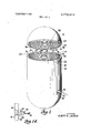
- FIG. 1 is an exploded, perspective view of the tamt perproof tamper resistant container of the present invention showing the method of providing both a me chanical and electrical connection between the container proper and its cover.
- FIG. la is a side elevation, partly in section, of a portion of the apparatus of FIG. 1.
- FIG. 2 is a perspective view of a partial section of an alternate embodiment of the present invention.
- FIG. 2a is an enlarged perspective view of a section of a modified container similar to the device shown in FIG. 2.
- FIG. 3 is a perspective view of yet another embodiment of the present invention showing multiple, overlapping, randomly applied electrical circuits applied as films to the inner surface of the container.
- FIG. 4 is a block diagram of the electrical network components positioned within the tamper resistant container of the present invention.
- the apparatus of this invention comprises a tamper resistant container including joined side and end walls forming a complete enclosure which may include a separable cover.
- a tamper resistant container including joined side and end walls forming a complete enclosure which may include a separable cover.
- There is provided within the container at least one electrical circuit having closely spaced wall-carried conductors with external or internal means provided for energizing the cirucit whereby any attempt to penetrate the container wall results in changing the electrical characteristics of the circuit.
- multiple, randomly applied conductors are sprayed on the inner surface of the container wall, each circuit being separated by a thin film of insulating material.
- the conductors form a part of an electrical network which may include a source of power, alarm means and/or self-destructive means as well as a circuit neutralizing device allowing neutralization of the detecting means through the application of a remote, correlated, radio signal.
- a typical tamper resistant container is shown to include a main container body 10 and a cover 12 which may be both mechanically and electrically connected.
- the container body 10 and the cover 12 may be formed of any material, preferably an insulator which may, for instance, be glass or other vitrified material.
- the type of glass may be a heat resistant glass, suitably hardened to resist entry; or alternately, the container including its cover may be formed of a highly stressed glass which would disintegrate upon attempted entry.
- the ma terial is opaque to increase the difficulty of entry and specifically to prevent viewing of the electrical circuit or circuits involving conductors randomly applied to the inner surface of the container wall in the form of thin films or the like or formed integrally within the wall itself.
- the interior or inner wall of the container is covered with one or more circuits formed by thin film conductors.
- the conductors 16 and 18 which may be silver or other metal of high conductivity, are shown in the FIG. 1 embodiment applied, respectively, to the inner surface 14 of the container body 10 and inner surface 20 of cover 12 in a somewhat regular pattern consisting of concentric circles in a spiral form, the individual conductors l6 and 18 being spaced slightly in the form of loops to prevent short-circuiting.
- the circuits formed thereby may be spray painted, etched, silk screened, or decaled in place by conventional coating processes.
- the spiral formed by the conductors may be protected by glazing or spraying with a plastic to provide an insulator over each circuit thus preventing inadvertent shorting of the circuitry by equipment or other apparatus installed within the container.
- the container may be of various sizes and shapes.
- the container shown in FIG. 1 may have an approximate volume of two cubic feet, being fourteen inches in diameter and 24 inches in length.
- the individual conductor width will be approximately 1/64 inch wide and l/OOO to 2/ 1000 inches thick.
- the conductors should be spaced l/64 inch apart in the spiral pattern shown for a container of this size.
- the container when in use forms a sealed enclosure having a single, continuous detection circuit with the cover 12 being mechanically and electrically secured to the main container body 10.
- clamps are used.
- the clamps include latch members 22 fixed to the outer surface of main container and catch members 24 fixed to the outer surface of cover 12.
- the main container body 10 is formed with an annular recess 26 at the open top to provide a rim 32 within the main container body 10. By undercutting the open end of cover 12, a projecting lip 28 is formed integrally therewith, thus forming a mechanical locating means between the main container body 10 and cover 12.
- the spiral conductor 16 formed within the, cover 12 includes a number of conductive portions or tabs 29 which extend downwardly through lip 28 to the exposed under-surface 30.
- the conductive tabs 29 actually pass through the lip 28 and are connected to the conductor forming the outermost spiral 36 of the conductor network within cover 12.
- the rim portion 32 formed by recess 26 within the container body 10 also has a number of conductive tab portions 34 which act as electrical connecting means to the outermost spiral 38 of conductor 18 of the electrical network within the container body 10.
- the respective spirals 36 and 38 of the cover and body portions of the container are electrically linked through conductive tabs 29 and 34 spaced circumferentially of the lip 28 and rim 32, respectively.
- a wet silver coating is applied to the conductor segments or tabs 29 and 34 only at the tab locations about the surface of rim 32 and protruding lip 28.
- a tab 33 is connected to an embedded vertical conductor (indicated by dotted lines 39) which runs to the center of cover 12 and is connected to the inner end of spiral conductor 16.
- a vertical embedded conductor 37 connects mating tab 34 to the inner end of spiral conductor 18.
- the power supply to the electrical circuit as well as the alarm device is remotely positioned from the container and the electrical connection is made through the use of socket 40 and plug 42 shown in FIG. la.
- the plug 42 may be formed of molded phenolic material and may include a series of prong receiving conductive apertures 44 located within the insulative body 42 and connected by conventional means to electrical leads 45 by means of insulated lead wire 46.
- the socket 40 is in the form of a plug receiving aperture and includes a like number of protruding prongs 48 which are received within apertures 44 to make the appropriate electrical connection.
- the male prong members 48 do not pass directly through the container wall but are electrically connected through the wall of the container 10 to embedded sinuous conductors 50 which pass through the wall.
- the inner ends of the conductors 50 are attached directly to spiral conductor 18 to form one or more circuits of the detecting network. While the embodiment shown in FIG. 1 includes but a single circuit formed by an elongated conductor in a spiral-like form about the inner surface of both the container body and its cover, it is preferable to form a number of individual circuits either in symmetrical or random fashion in which the individual conductors of the separate circuits actually overlap other conductors but are insulated therefrom.
- the main container body 10' which is formed of opaque glass, includes three different circuits formed in a somewhat symmetrical fashion with each circuit having parallel conductor sections.
- a first circuit is formed of conductors indicated at being vertically oriented with respect to and in line with the axis of the cylindrical container.
- a second elongated circuit is formed by parallel conductors 62 which are formed in somewhat the same spiral manner as conductors 16 and 18 of the first embodiment and are horizontally oriented with respect to container 10'.
- a third circuit is formed by diagonal, spaced conductors 64.
- the conductors 60, 62 and 64 overlap but, as mentioned previously, are separated by a transparent thin film insulation which may be sprayed on as the conductors are applied to the inner surface of container 10' in a sequential manner.
- the container 10 includes a recessed portion 66 forming a rim 68 upon which is formed a series of spaced electrical tabs or conductive portions.
- Tabs 70 are electrically connected to the ends of vertical conductors 60, tabs 72 to the diagonal conductors 64 and tabs 74 to the spiral horizontally oriented conductors 62. Again, specific connecting leads between the respective tab elements and the thin film circuit portion are not visible since the glass container 10' is preferably opaque. It is important to note that a similar pattern is formed within a cover (not shown) but the same type of electrical and mechanical connection occurs between the container 10' and its cover through the use of suitable mechanical latches (not shown). The wet silver electrical connecting technique is employed as in the previously described embodiment of FIG. 1.
- FIG. 2a shows the individual conductors insulated with Vycor glass tubing to facilitate fabrication with insulation allowing the different sheathed conductors to touch without shorting between circuits.
- FIG. 3 shows a third embodiment of the present invention in which a container 10" formed of opaque glass is provided with multiple, randomly applied circuits which overlap in the same manner as the FIG. 2 embodiment and in which the circuits are applied by spraying the conductor on the container wall in the form of thin film and by placing an insulating film between the respective multiple circuits.
- a first circuit would start at 80, while a second, completely different circuit would start at 82 and a third at 84.
- the first circuit may pass freely in random fashion about the circumference of the inner wall from top to bottom of the container, exit as indicated at 86 and be connected to an appropriate electrical connector tab 88.
- a circuit would be initiated at tab 90 as a result of conductors 80 and 86 to tab 88 for completion through a container cover (not shown).
- a container cover not shown.
- penetration of the container by a metal tool or the like would not only affect the electrical characteristics of any individual circuit, but would probably result in providing a shortened electrical path between one or more of the circuits since the circuits are applied in overlapping, insulated fashion.
- electrical connection between the cover and the container body is facilitated by the application of wet silver at the tab points which form electrical connections between circuits within the container body and its cover.
- a significant advantage lies in the utilization of a container of the type shown in FIG. 3 since the multiple separate electrical conductors formed within the container proper or along the inner surface of the opaque container are formed in a completely random fashion.
- the tamper resistant containers of FIG. 2 and FIG. 3 carry their own source of electrical power for energizing the circuits or associated apparatus.
- the container wall for a container such as 10' which includes a cover for forming a completely enclosed container surrounds appropriate electrical or electronic apparatus indicated in block form diagram.
- the electrical apparatus includes an electrical power source 100, such as a battery with or without inverter means, which is connected to the electrical circuits carried by the container walls as shown in FIGS. 2, 2a and 3.
- the power source is further coupled to an alarm or self-destructive device 104 through said circuits. With just these three elements forming the detection network, penetration will result in changing the electrical characteristics of the circuits which would activate either the alarm or the self-destructive device for destroying both the container and the material positioned therein.
- an additional device in the form of a tunable neutralizing receiver 106 is provided. It is also coupled directly to power source and to the alarm or selfdestructive device by circuit paths which by-pass circuits 102. An appropriate signal is generated by a transmitting device (not shown) exterior of the container to operate the neutralizing receiver and thus neutralizes the alarm or self-destructive circuit. At this point, penetration of the container may be made without effecting the alarm or self-destructive device 104.
- the tunable neutralizing receiver 106 may take the form of an electronic, radio receiver having a variable frequency setting such that the radio signal frequency to which the neutralizing device responds may be changed from day to day or from container to container with the frequency so set being noted for later correlation between a remote transmitting device and the particular container 10. This, in addition to the random application of circuits such as in the FIG. 3 embodiment would further increase resistance to successful tampering.
- each tamper resistant container is novel in its circuitry and may employ either single or multiple circuits wherein only the individual forming the circuit would know the specific pattern or configuration of the deposited conductor portion. It is further apparent that penetration of the container wall, since the inner wall is completely covered by slightly spaced, very thin conductors, would result in a change in the electrical characteristics of the individual circuits by varying circuit resistance, capacitance or inductance with the change operating any suitable, conventional alarm or self-destructive device.
- the conductors are wall carried"; they may be embedded in or applied to the inner surface of the container wall.
- the conductors on the container walls may be necessary to aircure a part of the conductors, at least the wet silver coatings applied to the tabs forming the connection between the container proper and its cover.
- conventional baking or heat curing processes may be utilized.
- the embodiments employing self-container power sources may use nickel cadmium batteries as the power source.
- the container and its coupler may be formed of highly stressed glass such that attempted penetration by drilling, etc. would break the cover and- /or the container in a great many pieces thus destroying the circuitry.
- a tamper resistant container including a main container body and a separable cover each having mating surfaces and defining a complete enclosure when said mating surfaces are placed in abutting relationship, at least one wall carried electrical circuit formed within respective cover and main body walls, conductive tabs placed in spaced relationship upon the mating surfaces of said cover and main container body, means for electrically connecting said circuits to said spaced tabs, means for electrically connecting corresponding tabs of said main container body and said cover, said connecting means including a wet silver film positioned between respective tabs with said films being air curable to insure completion of an electrical circuit between said main container body and said separable cover, and means for energizing said circuit whereby attempts to penetrate said container result in changing the electrical characteristics of said circuit.
- the apparatus as claimed in claim 1 further including latch means acting to mechanically couple said separable cover to said main container body wherein latching of said latch means enhances completion of the electrical circuit through said tabs and the sandwiched wet silver film.
- said container wall includes electrical connecting means in the form of transverse conductive members passing through said wall with a portion of said transverse conductors within said wall proper being suitably curved to effect misalignment between the terminal portions of said conductive members exteriorly and interiorly of said wall member.
Landscapes
- Physics & Mathematics (AREA)
- General Physics & Mathematics (AREA)
- Details Of Rigid Or Semi-Rigid Containers (AREA)
Abstract
1. A tamper resistant container including a main container body and a separable cover each having mating surfaces and defining a complete enclosure when said mating surfaces are placed in abutting relationship, at least one wall carried electrical circuit formed within respective cover and main body walls, conductive tabs placed in spaced relationship upon the mating surfaces of said cover and main container body, means for electrically connecting said circuits to said spaced tabs, means for electrically connecting corresponding tabs of said main container body and said cover, said connecting means including a wet silver film positioned between respective tabs with said films being air curable to insure completion of an electrical circuit between said main container body and said separable cover, and means for energizing said circuit whereby attempts to penetrate said container result in changing the electrical characteristics of said circuit.
Description
United States Patent [191 Jackson TAMPER RESISTANT CONTAINER Albert M. Jackson, Phoenix, Md.
[73] Assignee: Martin Marietta Corporation, New
York, NY.
22 Filed: Sept. 15, 1964 211 App]. No.: 397,672
[75] Inventor:
[52] U.S. Cl. 340/273 [51] Int. Cl. G08b 13/08 [58] Field of Search 102/8;
,Rr 'y Q a i -V9 95; ds tsee Attorney-Robert L. Berger, James B. Eisel and Gay Chin [ Nov. 13, 1973 EXEMPLARY CLAIM l. A tamper resistant container including a main container body and a separable cover each having mating surfaces and defining a complete enclosure when said mating surfaces are placed in abutting relationship, at least one wall carried electrical circuit formed within respective cover and main body walls, conductive tabs placed in spaced relationship upon the mating surfaces of said cover and main container body, means for electrically connecting said circuits to said spaced tabs, means for electrically connecting corresponding tabs of said main container body and said cover, said connecting means including a wet silver film positioned between respective tabs with said films being air curable to insure completion of an electrical circuit between said main container body and said separable cover, and means for energizing said circuit whereby attempts to penetrate said container result in changing the electrical characteristics of said circuit.
3 Claims, 6 Drawing Figures PATENTEBxnv 13 I973 SHEET 1 BF 2 w m Tc A md M H A PATENTEDIIIIV 13 I973 BLT/2.674
SHEET 2 BF 2 INVEBITOR. ALBERT M Md/$0M mm M .|||||\.II|mI| IIJ E- m m m, El R OnUvE v BLV MRC M E vmfiwl W UTC LEE K TUE ADD c M F L E5 R MA! E KA -$1- I I I l I I I I I I I I I I l I I I L TAMPER RESISTANT CONTAINER This invention relates to a tamper resistant container and more particularly to a container of this type having an internal tamper detection network including alarm means for immediate penetration disclosure.
There exists today the need for variable sized containers which would act to store valuable or classified material, either permanently or temporarily, in which penetration of the container in order to disclose the contents would either result in destruction of the container and its contents or would initiate an alarm indicating penetration. Many attempts have been made to provide tamper resistant containers. Some of these devices have included electrical or electronic detection networks including alarm devices such as audible sig nals or the like. One of the primary difficulties in effecting a true, tamper resistant container is the relative ease in determining the nature of the electrical circuit associated with the container thereby allowing penetration of the container without adversely afi'ecting the electrical circuit. Resultant penetration would allow nullification of the detection network and the alarm or self-destruction means after penetration.
It is therefore a primary object of this invention to provide a tamper resistant container including a novel penetration detection network which would indicate any attempt at penetration regardless of the size of the penetrating tool.
It is a further object of this invention to provide an improved tamper resistant container including a novel penetration detection network which would indicate any attempt at penetration regardless of the size of the penetrating tool.
It is a further object of this invention to provide an improved tamper resistant container including a detection network employing at least one randomly applied electrical circuit within the container in which only the individual forming the circuit within the container would know the specific configuration or pattern of the circuit thus formed.
It is a further object of this invention to provide an improved tamper resistant container including an electrical penetration detection network which has specific application to a container formed of highly stressed material.
It is a further object of this invention to provide an improved tamper resistant container including an electrical penetration detection network in which the power source and the alarm forming a portion of said network is wholly incorporated within the sealed, tamper resistant container.
It is a further object of this invention to provide an improved penetration detection network for a tamper resistant container which has applicability to a great variety of containers regardless of size or configuration.
Further objects of this invention will be pointed out in the following detailed description and claims and illustrated in the principle of this invention and the best mode which has been contemplated of applying that principle.
In the drawings:
FIG. 1 is an exploded, perspective view of the tamt perproof tamper resistant container of the present invention showing the method of providing both a me chanical and electrical connection between the container proper and its cover.
FIG. la is a side elevation, partly in section, of a portion of the apparatus of FIG. 1.
FIG. 2 is a perspective view of a partial section of an alternate embodiment of the present invention.
FIG. 2a is an enlarged perspective view of a section of a modified container similar to the device shown in FIG. 2.
FIG. 3 is a perspective view of yet another embodiment of the present invention showing multiple, overlapping, randomly applied electrical circuits applied as films to the inner surface of the container.
FIG. 4 is a block diagram of the electrical network components positioned within the tamper resistant container of the present invention.
In general, the apparatus of this invention comprises a tamper resistant container including joined side and end walls forming a complete enclosure which may include a separable cover. There is provided within the container at least one electrical circuit having closely spaced wall-carried conductors with external or internal means provided for energizing the cirucit whereby any attempt to penetrate the container wall results in changing the electrical characteristics of the circuit. In a preferred form, multiple, randomly applied conductors are sprayed on the inner surface of the container wall, each circuit being separated by a thin film of insulating material. The conductors form a part of an electrical network which may include a source of power, alarm means and/or self-destructive means as well as a circuit neutralizing device allowing neutralization of the detecting means through the application of a remote, correlated, radio signal.
Referring to FIG. 1 of the drawing, a typical tamper resistant container is shown to include a main container body 10 and a cover 12 which may be both mechanically and electrically connected. The container body 10 and the cover 12 may be formed of any material, preferably an insulator which may, for instance, be glass or other vitrified material. The type of glass may be a heat resistant glass, suitably hardened to resist entry; or alternately, the container including its cover may be formed of a highly stressed glass which would disintegrate upon attempted entry. Preferably, the ma terial is opaque to increase the difficulty of entry and specifically to prevent viewing of the electrical circuit or circuits involving conductors randomly applied to the inner surface of the container wall in the form of thin films or the like or formed integrally within the wall itself.
As indicated in FIG. l,'the interior or inner wall of the container is covered with one or more circuits formed by thin film conductors. The conductors 16 and 18 which may be silver or other metal of high conductivity, are shown in the FIG. 1 embodiment applied, respectively, to the inner surface 14 of the container body 10 and inner surface 20 of cover 12 in a somewhat regular pattern consisting of concentric circles in a spiral form, the individual conductors l6 and 18 being spaced slightly in the form of loops to prevent short-circuiting. The circuits formed thereby may be spray painted, etched, silk screened, or decaled in place by conventional coating processes. The spiral formed by the conductors may be protected by glazing or spraying with a plastic to provide an insulator over each circuit thus preventing inadvertent shorting of the circuitry by equipment or other apparatus installed within the container.
As mentioned previously, the container may be of various sizes and shapes. For instance, the container shown in FIG. 1 may have an approximate volume of two cubic feet, being fourteen inches in diameter and 24 inches in length. For a container of this size, the individual conductor width will be approximately 1/64 inch wide and l/OOO to 2/ 1000 inches thick. To prevent penetration of the container without disrupting the electrical characteristics of the circuit including the conductors l6 and 18, the conductors should be spaced l/64 inch apart in the spiral pattern shown for a container of this size.
As mentioned previously, the container when in use forms a sealed enclosure having a single, continuous detection circuit with the cover 12 being mechanically and electrically secured to the main container body 10. To effect mechanical attachment and locking, clamps are used. The clamps include latch members 22 fixed to the outer surface of main container and catch members 24 fixed to the outer surface of cover 12. The main container body 10 is formed with an annular recess 26 at the open top to provide a rim 32 within the main container body 10. By undercutting the open end of cover 12, a projecting lip 28 is formed integrally therewith, thus forming a mechanical locating means between the main container body 10 and cover 12.
The spiral conductor 16 formed within the, cover 12 includes a number of conductive portions or tabs 29 which extend downwardly through lip 28 to the exposed under-surface 30. The conductive tabs 29 actually pass through the lip 28 and are connected to the conductor forming the outermost spiral 36 of the conductor network within cover 12. In like manner, the rim portion 32 formed by recess 26 within the container body 10 also has a number of conductive tab portions 34 which act as electrical connecting means to the outermost spiral 38 of conductor 18 of the electrical network within the container body 10.
Thus, the respective spirals 36 and 38 of the cover and body portions of the container are electrically linked through conductive tabs 29 and 34 spaced circumferentially of the lip 28 and rim 32, respectively. To assure the desired electrical continuity between the portion of the circuit within cover 12 and the portion of the circuit within main container body 10, a wet silver coating is applied to the conductor segments or tabs 29 and 34 only at the tab locations about the surface of rim 32 and protruding lip 28. When the cover 12 is brought into contact with main container section 10 in proper circumferential orientation, the respective tab surfaces 29 and 34 will be in alignment and the wet silvered conductors touch and aircure, thus completing the circuit between conductors l6 and 18. The cover is physically secured in place by operating the latch means 22 to prevent inadvertent interruption of the circuitry. To complete the electrical circuit or circuits, a tab 33 is connected to an embedded vertical conductor (indicated by dotted lines 39) which runs to the center of cover 12 and is connected to the inner end of spiral conductor 16. Likewise, a vertical embedded conductor 37 connects mating tab 34 to the inner end of spiral conductor 18. It is apparent that any attempt to penetrate the container will either break the spiral conductor within cover 12 or main container body 10 or affect the electrical characteristics of the circuit in some related way to trigger detecting devices located within or exterior of the container itself.
In the embodiment shown in FIG. 1, the power supply to the electrical circuit as well as the alarm device is remotely positioned from the container and the electrical connection is made through the use of socket 40 and plug 42 shown in FIG. la. The plug 42 may be formed of molded phenolic material and may include a series of prong receiving conductive apertures 44 located within the insulative body 42 and connected by conventional means to electrical leads 45 by means of insulated lead wire 46. The socket 40 is in the form of a plug receiving aperture and includes a like number of protruding prongs 48 which are received within apertures 44 to make the appropriate electrical connection. In order to resist tampering in the area of the electrical connection, the male prong members 48 do not pass directly through the container wall but are electrically connected through the wall of the container 10 to embedded sinuous conductors 50 which pass through the wall. The inner ends of the conductors 50 are attached directly to spiral conductor 18 to form one or more circuits of the detecting network. While the embodiment shown in FIG. 1 includes but a single circuit formed by an elongated conductor in a spiral-like form about the inner surface of both the container body and its cover, it is preferable to form a number of individual circuits either in symmetrical or random fashion in which the individual conductors of the separate circuits actually overlap other conductors but are insulated therefrom. FIGS. 2, 2a and 3 show alternate embodimentsof this particular type. For instance, in FIG. 2 the main container body 10', which is formed of opaque glass, includes three different circuits formed in a somewhat symmetrical fashion with each circuit having parallel conductor sections. A first circuit is formed of conductors indicated at being vertically oriented with respect to and in line with the axis of the cylindrical container. A second elongated circuit is formed by parallel conductors 62 which are formed in somewhat the same spiral manner as conductors 16 and 18 of the first embodiment and are horizontally oriented with respect to container 10'. A third circuit is formed by diagonal, spaced conductors 64. The conductors 60, 62 and 64 overlap but, as mentioned previously, are separated by a transparent thin film insulation which may be sprayed on as the conductors are applied to the inner surface of container 10' in a sequential manner.
The container 10 includes a recessed portion 66 forming a rim 68 upon which is formed a series of spaced electrical tabs or conductive portions. Tabs 70 are electrically connected to the ends of vertical conductors 60, tabs 72 to the diagonal conductors 64 and tabs 74 to the spiral horizontally oriented conductors 62. Again, specific connecting leads between the respective tab elements and the thin film circuit portion are not visible since the glass container 10' is preferably opaque. It is important to note that a similar pattern is formed within a cover (not shown) but the same type of electrical and mechanical connection occurs between the container 10' and its cover through the use of suitable mechanical latches (not shown). The wet silver electrical connecting technique is employed as in the previously described embodiment of FIG. 1.
While the superimposed, insulated, multiple circuits are applied by film application techniques in the specific uniform patterns already described, the same patterns may be employed in an alternate structure in which the conductors are actually molded into the glass wall of the container. FIG. 2a shows the individual conductors insulated with Vycor glass tubing to facilitate fabrication with insulation allowing the different sheathed conductors to touch without shorting between circuits.
Instead of forming conductors of thin films in a spiral-like configuration on the inner wall surface of both the container body and its cover, an alternate approach is to mold the conductors in the glass walls. These conductors are insulated with Vycor glass tubing to facilitate fabrication with the insulation and allow con ductors to touch without shorting. For a container of the dimensions noted previously, the wall thickness in the case of this design would be from inch to inch in thickness. This particular container design would not only be economical to manufacturer initially due to the prefabricated conductors but would allow salvage of the container body when authorized entry was necessary for maintenance. With the exception that the conductors are embedded, the arrangement is identical with FIG. 2. Thus, tabs 70' connect embedded vertical conductors 60' with the container body to like vertical conductors of the cover (not shown). Likewise, tabs 72 are connected to embedded horizontal conductors 62, whiletabs 74 are connected to diagonal conductors 64' for completion of respective circuits between the container body 10" and the cover.
FIG. 3 shows a third embodiment of the present invention in which a container 10" formed of opaque glass is provided with multiple, randomly applied circuits which overlap in the same manner as the FIG. 2 embodiment and in which the circuits are applied by spraying the conductor on the container wall in the form of thin film and by placing an insulating film between the respective multiple circuits. For instance, starting at the rear center of the container 10 and moving to the right, a first circuit would start at 80, while a second, completely different circuit would start at 82 and a third at 84. The first circuit may pass freely in random fashion about the circumference of the inner wall from top to bottom of the container, exit as indicated at 86 and be connected to an appropriate electrical connector tab 88. Thus, a circuit would be initiated at tab 90 as a result of conductors 80 and 86 to tab 88 for completion through a container cover (not shown). In the embodiments of FIG. 2, 2a and 3, penetration of the container by a metal tool or the like would not only affect the electrical characteristics of any individual circuit, but would probably result in providing a shortened electrical path between one or more of the circuits since the circuits are applied in overlapping, insulated fashion. Again in both the FIG. 2a and FIG. 3 cmbodiments, electrical connection between the cover and the container body is facilitated by the application of wet silver at the tab points which form electrical connections between circuits within the container body and its cover. I
A significant advantage lies in the utilization of a container of the type shown in FIG. 3 since the multiple separate electrical conductors formed within the container proper or along the inner surface of the opaque container are formed in a completely random fashion. Once the cover has been attached and an electrical connection completed between the cover portion and the main container body 10", there is no way in which the conductor configuration or path may be determined without the aid of expensive x-ray equipment. A
prime advantage lies in this specific embodiment since only the operator forming the random pattern would know the specific pattern of the multiple conductor, and since each container would have a different pattern when manufactured in this form, the likelihood of penetration without affecting the electrical circuity is greatly diminished and as a matter of fact, practically impossible under these circumstances. It is intended that these circuits would be completely random at the sole discretion of the operator applying the circuits. That is, he would apply each conductor path randomly, with no prearranged pattern. This would have the effect that no one including the operator himself, would be able to describe just how the circuits are arranged in any given container. Also, there would of course be no drawings of the circuit configurations which might compromise the security of the device.
Unlike the arrangement illustrated in FIG. 1, the tamper resistant containers of FIG. 2 and FIG. 3 carry their own source of electrical power for energizing the circuits or associated apparatus. Referring to FIG. 4, it is noted that the container wall for a container such as 10' which includes a cover for forming a completely enclosed container surrounds appropriate electrical or electronic apparatus indicated in block form diagram. The electrical apparatus includes an electrical power source 100, such as a battery with or without inverter means, which is connected to the electrical circuits carried by the container walls as shown in FIGS. 2, 2a and 3. The power source is further coupled to an alarm or self-destructive device 104 through said circuits. With just these three elements forming the detection network, penetration will result in changing the electrical characteristics of the circuits which would activate either the alarm or the self-destructive device for destroying both the container and the material positioned therein.
Normally, once the container is mechanically and electrically sealed by latching the cover, no entry into the interior of the container is desired. However, in the case of the package unit, such as that shown in FIG. 4, an additional device in the form of a tunable neutralizing receiver 106 is provided. It is also coupled directly to power source and to the alarm or selfdestructive device by circuit paths which by-pass circuits 102. An appropriate signal is generated by a transmitting device (not shown) exterior of the container to operate the neutralizing receiver and thus neutralizes the alarm or self-destructive circuit. At this point, penetration of the container may be made without effecting the alarm or self-destructive device 104. The tunable neutralizing receiver 106 may take the form of an electronic, radio receiver having a variable frequency setting such that the radio signal frequency to which the neutralizing device responds may be changed from day to day or from container to container with the frequency so set being noted for later correlation between a remote transmitting device and the particular container 10. This, in addition to the random application of circuits such as in the FIG. 3 embodiment would further increase resistance to successful tampering.
From the above, it is obvious that each tamper resistant container is novel in its circuitry and may employ either single or multiple circuits wherein only the individual forming the circuit would know the specific pattern or configuration of the deposited conductor portion. It is further apparent that penetration of the container wall, since the inner wall is completely covered by slightly spaced, very thin conductors, would result in a change in the electrical characteristics of the individual circuits by varying circuit resistance, capacitance or inductance with the change operating any suitable, conventional alarm or self-destructive device. The conductors are wall carried"; they may be embedded in or applied to the inner surface of the container wall. In forming the conductors on the container walls by thin film techniques, it may be necessary to aircure a part of the conductors, at least the wet silver coatings applied to the tabs forming the connection between the container proper and its cover. To effect accelerated curing of either the deposited conductors or the wet silver tab connectors, conventional baking or heat curing processes may be utilized. The embodiments employing self-container power sources may use nickel cadmium batteries as the power source. In one alternative form, the container and its coupler may be formed of highly stressed glass such that attempted penetration by drilling, etc. would break the cover and- /or the container in a great many pieces thus destroying the circuitry.
While there have been shown and described and pointed out the fundamental novel features of the invention as applied to a preferred embodiment, it will be understood that various omissions and substitutions and changes in the form and detail of the device illustrated and in its operation may be made by those skilled in the art without departing from the spirit of the invention. It is the intention, therefore, to be limited only as indicated by the scope of the following claims.
What is claimed is:
l. A tamper resistant container including a main container body and a separable cover each having mating surfaces and defining a complete enclosure when said mating surfaces are placed in abutting relationship, at least one wall carried electrical circuit formed within respective cover and main body walls, conductive tabs placed in spaced relationship upon the mating surfaces of said cover and main container body, means for electrically connecting said circuits to said spaced tabs, means for electrically connecting corresponding tabs of said main container body and said cover, said connecting means including a wet silver film positioned between respective tabs with said films being air curable to insure completion of an electrical circuit between said main container body and said separable cover, and means for energizing said circuit whereby attempts to penetrate said container result in changing the electrical characteristics of said circuit.
2. The apparatus as claimed in claim 1 further including latch means acting to mechanically couple said separable cover to said main container body wherein latching of said latch means enhances completion of the electrical circuit through said tabs and the sandwiched wet silver film.
3. The apparatus as claimed in claim 1 wherein said container wall includes electrical connecting means in the form of transverse conductive members passing through said wall with a portion of said transverse conductors within said wall proper being suitably curved to effect misalignment between the terminal portions of said conductive members exteriorly and interiorly of said wall member.
Claims (3)
1. A tamper resistant container including a main container body and a separable cover each having mating surfaces and defining a complete enclosure when said mating surfaces are placed in abutting relationship, at least one wall carried electrical circuit formed within respective cover and main body walls, conductive tabs placed in spaced relationship upon the mating surfaces of said cover and main container body, means for electrically connecting said circuits to said spaced tabs, means for electrically connecting corresponding tabs of said main container body and said cover, said connecting means including a wet silver film positioned between respective tabs with said films being air curable to insure completion of an electrical circuit between said main container body and said separable cover, and means for energizing said circuit whereby attempts to penetrate said container result in changing the electrical characteristics of said circuit.
2. The apparatus as claimed in claim 1 further including latch means acting to mechanically couple said separable cover to said main container body wherein latching of said latch means enhances completion of the electrical circuit through said tabs and the sandwiched wet silver film.
3. The apparatus as claimed in claim 1 wherein said container wall includes electrical connecting means in the form of transverse conductive members passing through said wall with a portion of said transverse conductors within said wall proper being suitably curved to effect misalignment between the terminal portions of said conductive members exteriorly and interiorly of said wall member.
Applications Claiming Priority (1)
| Application Number | Priority Date | Filing Date | Title |
|---|---|---|---|
| US39767264A | 1964-09-15 | 1964-09-15 |
Publications (1)
| Publication Number | Publication Date |
|---|---|
| US3772674A true US3772674A (en) | 1973-11-13 |
Family
ID=23572167
Family Applications (1)
| Application Number | Title | Priority Date | Filing Date |
|---|---|---|---|
| US00397672A Expired - Lifetime US3772674A (en) | 1964-09-15 | 1964-09-15 | Tamper resistant container |
Country Status (1)
| Country | Link |
|---|---|
| US (1) | US3772674A (en) |
Cited By (15)
| Publication number | Priority date | Publication date | Assignee | Title |
|---|---|---|---|---|
| US3952295A (en) * | 1972-09-05 | 1976-04-20 | Gentex Corporation | Alarm system for cargo box |
| WO1983000246A1 (en) * | 1981-07-06 | 1983-01-20 | Jorgensen, Poul, Richter | Alarm system for safeguarding against the breakthrough of a surface |
| US5224430A (en) * | 1991-06-21 | 1993-07-06 | W. L. Gore & Associates, Inc. | Security enclosures |
| US20010014944A1 (en) * | 1998-09-29 | 2001-08-16 | Fujitsu Limited | Data communication device |
| US20010056542A1 (en) * | 2000-05-11 | 2001-12-27 | International Business Machines Corporation | Tamper resistant card enclosure with improved intrusion detection circuit |
| US20020049910A1 (en) * | 2000-07-25 | 2002-04-25 | Salomon Allen Michael | Unified trust model providing secure identification, authentication and validation of physical products and entities, and processing, storage and exchange of information |
| USD458837S1 (en) | 2000-08-23 | 2002-06-18 | Invicta Plastics Limited | Dispenser |
| US20030137416A1 (en) * | 2000-06-01 | 2003-07-24 | Shuzhen Fu | Point of sale (POS) terminal security system |
| US20070120669A1 (en) * | 2005-11-29 | 2007-05-31 | Alpha Security Products, Inc. | Security device with perimeter alarm |
| US20080316028A1 (en) * | 2005-11-29 | 2008-12-25 | Conti Brian V | Security device with perimeter alarm |
| US20090045254A1 (en) * | 2006-03-23 | 2009-02-19 | Giovanni Carapelli | Device for checking the regularity of the operation of automatic payment terminals |
| US20110095919A1 (en) * | 2008-02-20 | 2011-04-28 | Hypercom Gmbh | Keyboard having capacitance-sensitive key fields |
| US8621235B2 (en) | 2011-01-06 | 2013-12-31 | Verifone, Inc. | Secure pin entry device |
| US8884757B2 (en) | 2011-07-11 | 2014-11-11 | Verifone, Inc. | Anti-tampering protection assembly |
| USD1081110S1 (en) * | 2022-07-13 | 2025-07-01 | Athena Club Holdings, Inc. | Pill dispenser |
Citations (5)
| Publication number | Priority date | Publication date | Assignee | Title |
|---|---|---|---|---|
| US126289A (en) * | 1872-04-30 | Improvement in electrical linings for safes, vaults | ||
| US181078A (en) * | 1876-08-15 | Improvement in electric burglar-alarms | ||
| US2411787A (en) * | 1942-09-26 | 1946-11-26 | Rca Corp | Radio controlled mine |
| US2950400A (en) * | 1942-03-30 | 1960-08-23 | Itt | Protective circuit for radio repeater |
| US3051934A (en) * | 1958-12-01 | 1962-08-28 | Martha H Egly | Building protection system |
-
1964
- 1964-09-15 US US00397672A patent/US3772674A/en not_active Expired - Lifetime
Patent Citations (5)
| Publication number | Priority date | Publication date | Assignee | Title |
|---|---|---|---|---|
| US126289A (en) * | 1872-04-30 | Improvement in electrical linings for safes, vaults | ||
| US181078A (en) * | 1876-08-15 | Improvement in electric burglar-alarms | ||
| US2950400A (en) * | 1942-03-30 | 1960-08-23 | Itt | Protective circuit for radio repeater |
| US2411787A (en) * | 1942-09-26 | 1946-11-26 | Rca Corp | Radio controlled mine |
| US3051934A (en) * | 1958-12-01 | 1962-08-28 | Martha H Egly | Building protection system |
Cited By (23)
| Publication number | Priority date | Publication date | Assignee | Title |
|---|---|---|---|---|
| US3952295A (en) * | 1972-09-05 | 1976-04-20 | Gentex Corporation | Alarm system for cargo box |
| WO1983000246A1 (en) * | 1981-07-06 | 1983-01-20 | Jorgensen, Poul, Richter | Alarm system for safeguarding against the breakthrough of a surface |
| US5224430A (en) * | 1991-06-21 | 1993-07-06 | W. L. Gore & Associates, Inc. | Security enclosures |
| US20010014944A1 (en) * | 1998-09-29 | 2001-08-16 | Fujitsu Limited | Data communication device |
| US20010056542A1 (en) * | 2000-05-11 | 2001-12-27 | International Business Machines Corporation | Tamper resistant card enclosure with improved intrusion detection circuit |
| US6957345B2 (en) * | 2000-05-11 | 2005-10-18 | International Business Machines Corporation | Tamper resistant card enclosure with improved intrusion detection circuit |
| US20030137416A1 (en) * | 2000-06-01 | 2003-07-24 | Shuzhen Fu | Point of sale (POS) terminal security system |
| US6917299B2 (en) * | 2000-06-01 | 2005-07-12 | Hewlett-Packard Development Company, L.P. | Point of sale (POS) terminal security system |
| US20020049910A1 (en) * | 2000-07-25 | 2002-04-25 | Salomon Allen Michael | Unified trust model providing secure identification, authentication and validation of physical products and entities, and processing, storage and exchange of information |
| USD458837S1 (en) | 2000-08-23 | 2002-06-18 | Invicta Plastics Limited | Dispenser |
| US20070120669A1 (en) * | 2005-11-29 | 2007-05-31 | Alpha Security Products, Inc. | Security device with perimeter alarm |
| US7403118B2 (en) * | 2005-11-29 | 2008-07-22 | Checkpoint Systems, Inc. | Security device with perimeter alarm |
| US20080316028A1 (en) * | 2005-11-29 | 2008-12-25 | Conti Brian V | Security device with perimeter alarm |
| US7659817B2 (en) | 2005-11-29 | 2010-02-09 | Checkpoint Systems, Inc. | Security device with perimeter alarm |
| US20090045254A1 (en) * | 2006-03-23 | 2009-02-19 | Giovanni Carapelli | Device for checking the regularity of the operation of automatic payment terminals |
| US8132721B2 (en) | 2006-03-23 | 2012-03-13 | Gilbarco Inc. | Device for checking the regularity of the operation of automatic payment terminals |
| US20110095919A1 (en) * | 2008-02-20 | 2011-04-28 | Hypercom Gmbh | Keyboard having capacitance-sensitive key fields |
| US8621235B2 (en) | 2011-01-06 | 2013-12-31 | Verifone, Inc. | Secure pin entry device |
| US8954750B2 (en) | 2011-01-06 | 2015-02-10 | Verifone, Inc. | Secure PIN entry device |
| US9792803B2 (en) | 2011-01-06 | 2017-10-17 | Verifone, Inc. | Secure PIN entry device |
| US8884757B2 (en) | 2011-07-11 | 2014-11-11 | Verifone, Inc. | Anti-tampering protection assembly |
| US9390601B2 (en) | 2011-07-11 | 2016-07-12 | Verifone, Inc. | Anti-tampering protection assembly |
| USD1081110S1 (en) * | 2022-07-13 | 2025-07-01 | Athena Club Holdings, Inc. | Pill dispenser |
Similar Documents
| Publication | Publication Date | Title |
|---|---|---|
| US3772674A (en) | Tamper resistant container | |
| US2691698A (en) | Security telephone cable with jammer and alarm | |
| US5510770A (en) | Surface deactivateable tag | |
| US3742478A (en) | Circuit board motion sensitive switch | |
| GB1304510A (en) | ||
| US4578670A (en) | Alarm system for safeguarding against the break-through of a surface | |
| US11024587B2 (en) | Self-destructible apparatus and method and semiconductor chip using the same | |
| DK159586B (en) | SAFETY CONTAINER | |
| JPS6213720B2 (en) | ||
| US3914756A (en) | Portable alarm actuated by attempted theft | |
| US2541461A (en) | Electronic combination switch | |
| IE45963L (en) | Vibration sensing device | |
| US3609742A (en) | Property security system | |
| US3729602A (en) | Tilt responsive switch with ball contact actuating structure | |
| JPS5233450A (en) | Microwave integrated circuit unit | |
| US4132987A (en) | Security system | |
| US1372570A (en) | Electrical testing apparatus | |
| US3036297A (en) | Key device | |
| CN2052561U (en) | Multi-functional electron tog bricks | |
| WO1991012598A1 (en) | A security system for surveilling the passage of commodities through defined zones | |
| US2979575A (en) | Communication system | |
| JPS5250587A (en) | Connector | |
| JPS5327465B1 (en) | ||
| GB1425373A (en) | Thick film electrical circuits | |
| US497430A (en) | Circuit-protector |