US3772647A - Data verification for electronic knitting machine - Google Patents
Data verification for electronic knitting machine Download PDFInfo
- Publication number
- US3772647A US3772647A US00239058A US3772647DA US3772647A US 3772647 A US3772647 A US 3772647A US 00239058 A US00239058 A US 00239058A US 3772647D A US3772647D A US 3772647DA US 3772647 A US3772647 A US 3772647A
- Authority
- US
- United States
- Prior art keywords
- knit
- indications
- feeder
- data
- pattern
- Prior art date
- Legal status (The legal status is an assumption and is not a legal conclusion. Google has not performed a legal analysis and makes no representation as to the accuracy of the status listed.)
- Expired - Lifetime
Links
Images

Classifications
-
- D—TEXTILES; PAPER
- D04—BRAIDING; LACE-MAKING; KNITTING; TRIMMINGS; NON-WOVEN FABRICS
- D04B—KNITTING
- D04B15/00—Details of, or auxiliary devices incorporated in, weft knitting machines, restricted to machines of this kind
- D04B15/66—Devices for determining or controlling patterns ; Program-control arrangements
-
- D—TEXTILES; PAPER
- D04—BRAIDING; LACE-MAKING; KNITTING; TRIMMINGS; NON-WOVEN FABRICS
- D04B—KNITTING
- D04B35/00—Details of, or auxiliary devices incorporated in, knitting machines, not otherwise provided for
- D04B35/10—Indicating, warning, or safety devices, e.g. stop motions
Definitions
- ABSTRACT The present invention provides a method and apparatus for verifying knitting machine data which has been prepared from a pattern drawing and will be used by an electronically controlled circular knitting machine or by a pin setting machine for setting pins in pattern drums or wheels.
- the knitting pattern data includes knit and non-knit indications which are stored at memory locations on a suitable memory means such as punched paper tape, magnetic tape, or a magnetic disc or drum Verification is effected by logically examining all of the knit and non-knit instructions for each stitch of each stitchrow of the pattern defined by the knitting pattern data. If the combination of knit and non-knit instructions for a stitch does not conform to the format for the type of fabric to be knitted, then readout devices indicate the stitchrow and stitch number where the error exists.
- a known electronic knitting machine includes a control apparatus having a magnetic data storage unit in which digital pattern data is stored.
- This digital pattern data includes knit and non-knit instructions which control the operation of groups of feeders to knit the stitchrows of a pattern during operation of the knitting machine.
- a known electronic knitting machine having such a control apparatus is disclosed in U.S. Pat. application Ser. No. 193,047, filed Oct. 27, 1971 by Paul Christiansen and entitled Knitting Machine Control.
- the control apparatus of the Christiansen application is advantageously used in conjunction with the code converter disclosed in US. Pat. application Ser. No. 192,984, filed Oct. 1971 2971 by Ralph I-I. Schuman and entitled Knitting Machine Encoder.
- the knitting of a selected pattern requires that thousands of knit and non-knit instructions be provided for each feeder.
- the knitting of a relatiyely simple three-color plain pattern which is 208 stitches wide and 216 stitchrows high with a circular knitting machine having 36 feeders requires the recording of 134,784 instructions to either knit or non-knit. Since a relatively large number of instructions must be provided to knit even a simple pattern, it is probable that there will be at least some errors in the recorded pattern data. Of course if there is an error in the recorded pattern data, the knitting machine will not knit the desired pattern faithfully.
- Another object of this invention is to provide a new and improved apparatus for detecting the presence of an error in control data having knit and non-knit indications which are to be utilized to effect activation of a plurality of feeders to knit a stitchrow of a predetermined pattern, and wherein the apparatus includes a verification device for determining if the combination of knit and non-knit indications associated with the plurality of feeders for a stitch of the stitchrow corresponds to a combination of knit and non-knit indications which is in accordance with the predetermined format.
- Another object of this invention is to provide a new and improved apparatus for detecting the presence of an error in digital pattern data which is to be utilized to effect activation of at least some of the feeders of a knitting machine during the knitting of a predetermined pattern, and wherein'the apparatus includes a verification device for logically examining digital pattern data retrieved from memory locations to determine if the digital pattern data is in accordance with the predetermined. format.
- Another object of this invention is to provide a new and improved apparatus in accordance with the next preceding object and wherein the verification device includes logic circuitry for detecting digital pattern data which is not in accordance with the predetermined format.
- Another object of this invention is to provide a new and improved apparatus for detecting the presence of an error in a selected one of a plurality of sets of pattern data, each set of which represents a different knitted pattern and is utilized to effect activation of a plurality of groups of feeders to knit different stitchrows of the pattern, and wherein the apparatus includes a verification device for determining if a combination of knit and non-knit indications associated with each feeder of a feeder group for a stitch of a stitchrow corresponds to a combination of knit and non-knit indications which is in accordance with the format associated with the selected set of pattern data.
- Another object of this invention is to provide a new and improved apparatus in accordance with the next preceding object and wherein the apparatus further includes a plurality of registers each of which is capable of holding the knit and non-knit indications associated with one of the feeders for a stitchrow of the pattern represented by the selected set of pattern data, circuitry for effecting the transmittal of knit and non-knit indications associated with different feeders to different registers of the plurality of registers, and apparatus for effecting the simultaneous transmission from the plurality of the registers to the verification device of knit and non-knit indications associated with each feeder of a feeder group for a stitch of the stitchrow.
- Another object of this invention is to provide a new and improved method of detecting an error in data having knit and non-knit indications which are to be utilized to effect activation of a plurality of feeders during the knitting of a predetermined pattern and wherein the method includes the steps of determining the combination of knit and non-knit indications which are associated with the plurality of feeders for a stitch of the stitchrow and determining if the combination of knit and non-knit indications associated with the plurality of feeders for a stitch of the stitchrow corresponds to a combination of knit and non-knit indications which is in accordance with the predetermined format.
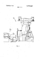
- FIG. 1 is a schematic illustration depicting a circular knitting machine, electronic control apparatus for the knitting machine, and a data verification device constructed in accordance with the present invention
- FIG. 2 is a schematic illustration of a portion of a four-color plain knitted pattern
- FIG. 3 is a schematic illustration of data for controlling the operation of a knitting machine to knit the four-color plain pattern of FIG. 2;
- FIG. 4 is a schematic illustration depicting the storage location of digital pattern data on a magnetic memory disc
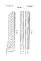
- FIG. 5 is an illustration of a portion of a punched paper tape for programming the magnetic memory disc of FIG. 4;
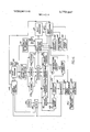
- FIG. 6 is a schematic illustration of control circuitry in the verification device.
- FIG. 7 is a schematic illustration of logic circuitry which is included in the data verification circuitry of FIG. 6.
- FIG. 1 shows diagramatically an electronic knitting control 91 connected to the knitting machine by a cable 92.
- Control 91 contains an active memory device, which in the preferred embodiment is a magnetic disc unit 93. Data is transferred from magnetic disc unit 93 to a plurality of electromagnetic actuators (not shown) on knitting machine 90 in response to signals generated by an optical shaft encoder 94.
- an optical shaft encoder 94 For a more complete description of the encoder 94 and controls 91, reference is made to the aforementioned US. Pat. application Ser. Nos.
- a data verification apparatus of the present invention is indicated generally at 100 in FIG. 1.
- a multiple conductor electrical connector 96 selectively connects the apparatus 100 to any one of a plurality of knitting controls 91.
- FIG. 2 a small portion of a pattern is illustrated in FIG. 2.
- the particular pattern used for illustration is a four-color plain pattern.
- the fourcolors are identified as A, B, C and D.
- This pattern requires four feeders per stitchrow. That is, groups of four adjacent feeders of the knitting machine are threaded with thread of colors A, B, C and D. If the stitch to be knitted at a particular place in the fabric is color B, then the knitting needle that knits that particular stitch will not knit at the feeders with thread of colors A, C or D, but will knit at the feeder with thread of color B.
- the digital pattern data for controlling the first four feeders of the knitting machine to knit the first partial stitchrow of the pattern of FIG. 2 is represented in FIG. 3.
- a 1" indicates knit and a indicates non-knit.
- stitches 1, 2 and 3 will be knitted at the feeder with thread of color C
- stitches 4, 5 and 6 will be knitted at the feeder with thread of color D, and so on.
- a needle should knit once and only once in a four feeder group. Therefore, the data must contain one and only one knit command, or 1, for each stitch. The absence of a 1" or the presence of more than one l for a given stitch would be an error in the data.
- the formation of the stitches is different, and therefore the data format is different.
- a needle For a three-color double blister pattern with two background colors, a needle must either knit one of the two background colors, or it must knit the blister color.
- the blister color is threaded on two feeders out of each group of four. If the needle knits at the first blister color feeder of a four feeder group, then it must also knit at the other blister color feeder of the four feeder group.
- each type of pattern requires a certain data format.
- the present invention provides an apparatus 100 and method for detecting the presence of an error in the pattern data.
- the apparatus 100 includes logic circuitry which examines the combination of knit and non-knit indications for each stitch to determine if the combination of knit and non-knit indications is in accordance with the desired format. Because the data format may be checked automatically by electronic digital logic circuitry, most data errors may be detected rapidly and conveniently.
- Such offsetting errors may be avoided by preparing the knitting data in such a way that the data for each feeder is generated substantially independently of the data for every other feeder.
- the probability of the occurence of compensating errors when the data for each feeder is prepared independently is statistically very small. Therefore, where feeder data is independently generated, a check of the knitting data format provides a very reliable check of the correctness of the data.
- the data is generated stitchrow by stitchrow.
- Data generation may be performed manually or may be performed automatically by an optical scanning device capable of distinguishing color.
- the data for each knitting machine feeder for each stitchrow of the pattern is in the form of a series of 1 and 0" representations and is arranged in a block which is assigned an identification code.
- the identification code for each block of data is chosen to be the same as the memory address of the location in the active storage device 93 used in the knitting machine control 91.
- This arrangement permits data to be directly loaded from punched paper tape into knitting control active storage without decoding or recoding the identification codes.
- the particular scheme used with the apparatus of the present invention is the same as that described in the Schuman and Christiansen application Ser. Nos. 192,984 and 193,047 referred to above.
- each memory address is comprised of two parts; one part associated with each particular feeder and the other part associated with knitting machine revolutions.
- the pattern data to be used by a particular feeder during a particular revolution of the knitting machine is always stored in the same active memory address location.
- FIG. 4 illustrates the relationship between the feeders and the memory addresses.
- data for feeder F0 is located on track T0 in zone ZO.
- Data for feeder F5 is located on track T1 in zone Z1, and so on.
- Each zone is subdivided into sectors, each of which stores data for use by one feeder to knit one stitchrow of a pattern. Because the knitting machine 90 knits repeats of a pattern during each revolution, the data in one sector is used repeatedly and will control a feeder for one full revolution of the knitting machine.
- the knitting data is retrieved from disc storage 93 under control of encoder 94 which generates memory addresses as a function of knitting machine rotation.
- the first feeder group would include feeders F0, F1, F2, and F3.
- the knit and non-knit indications for the first stitchrow knitted by these feeders all have memory or identification addresses of track T and sector S0.
- the zone address will be either Z0, Z1, Z2, or Z3 depending upon the feeder number.
- the digital pattern data for any given pattern is programmed into the magnetic disc storage 93 from a punched paper tape 97, a portion of which is shown in FIG. 5.
- the punched paper tape 97 contains the knit and non-knit indications for effecting operation of each feeder of the knitting machine 90 to knit the associated pattern.
- the paper tape 97 contains all of the pattern data necessary to program the magnetic disc storage unit 93 and effect operation of the knitting machine 90 to knit a pattern determined by the data. Since the data of the tape 97 will be associated with many different memory address locations in the magnetic disc storage unit 93, the 8-channel tape has a plurality of blocks of data 98 (only one of which is shown in FIG. which are identified by a memory address code 99 punched in the tape. Each data block contains the knit and non-knitdata 98 associated with one feeder for a stitchrow of a pattern. Thus, the digital pattern data in one data block is sufficient to program one sector of the magnetic data storage 93. The sector number, track number, and zone number associated with the block of data are identified by the code 99 which is immediately before the data 98.
- Channels 1-6 of each character space in the data 98 are used to store the knit and non-knit commands.
- a hole indicates a l or knit; the absence of a hole indicates a 0, or non-knit.
- the apparatus is presently designed for patterns having a maximum width of 208 stitches. This requires 35 character spaces of the tape, with channels 5 and 6 of the 35th character space not used. In the future, patterns having a width of 256 stitches are contemplated. For these patterns, 43 character spaces will be required, with channels 5 and 6 of the 43rd character space not used.
- a hole punched in channel 7 of a character space identifies it as a data character.
- the identification code 99 is punched in accordance with the EIA standard for S-channel punched paper tape, however, only the letters T,S,Z and the numerals 0-9 are used. This avoids characters with a punched hole in either channel 7 or channel 8. As noted above, channel 7 is used to indicate data. Channel 8 is used to indicate the end of a block of data.
- Knitting pattern data on punched paper tape 97 is read by a tape reader 102 under the control of tape reader control circuitry 103.
- the tape reader control circuitry is responsive to certain commands on the punched tape 97 as well as signals from other parts of the apparatus.
- Letter and number recognition and gating circuitry 104 connected to tape reader 102 recognizes predetermined letter codes and in response thereto gates following number codes to specified storage device 105. More particularly, circuitry 104 is adapted to recognize the letters Z, T, and S, which stand for zone, track and sector, respectively. Circuitry 104 also distinguishes between letters and numbers. When circuitry 104 recognizes a Z, T, or S, it will gate the next two characters to the proper storage device 105, providing the next two characters are numbers.
- the active storage address for a particular block of digital pattern data is track 7, zone 3, sector 22.
- the identification or memory address code for this block of digital pattern data on the punched paper tape would be T07Z03S22.
- circuitry 104 will recognize the letter T, gate the numerals 07 to storage device 105a; recognize the letter Z, gate the numerals 03 to storage device l05b; and recognize the letter S, and gate the numerals 22 to storage device 1056.
- the identification or address code for each block of digital pattern data that passes under the read head of tape reader is loaded into storage devices 105.
- a comparator 1 l 1 When the particular block of data required has its identification code stored in storage devices 105, a comparator 1 l 1 produces an output signal to shift register selection and gating circuitry 122, which activates one of a plurality of shift registers 113.
- Data parallel to serial conversion circuitry 114 is arranged to distinguish between knitting data and all other information on tape 101, and to convert the data bits from the 6-bit parallel groupings in which they are stored on tape 97 to serial groups for loading one of the activated shift registers 113.
- Circuitry 1 14 includes a digital clock that operates at a frequency sufficient to clock six bits of data into the activated shift register 113 well within the sprocket time of tape reader 102.
- pattern stitchrows have a fixed relationship to knitting machine feeder groups and knitting machine revolutions.
- a stitchrow number may be set manually on thumbwheel switches 121 which provide the steering inputs to a presettable BCD counter 122.
- the number set on thumbwheel switches 121 may be loaded into counter 122 by manually depressing a pushbutton 123.
- Each stage of counter 122 is connected to one side of a comparator 124, the other side of which is connected to the stages of another BCD counter 125.
- Counter 125 is advanced by pulses from a clock 131.
- the pulses are selectively passed or blocked by a gate 132 and by divider gates 133.
- Gate 132 acts merely as a switch to pass all pulses or to block all pulses.
- Divider gates 133 pass every second, third, or fourth pulse to effectively perform division.
- the effective divisor is determined by the setting of a pattern type selector switch 134. If the pattern type selected requires four feeders per stitch row, the effective divisor is four. If 3 feeders per stitchrow are required for the selected pattern type, the divisor is three. And, if 2 feeders per stitchrow are required, the divisor is two.
- the pattern selector switch 134 enables data for a selected one of a plurality of pattern types to be verified by the verification device 100.
- Pulses from clock 131 are used to advance three binary counters 135, 136 and 137.
- Counter 135 receives all pulses from clock 131 that are passed by gate 132.
- Counter 135 counts repetitively through the number of zones of the disc memory address, which in the present embodiment is four. Additional zones will be used in future embodiments. Four counts are provided, of course, by counting -3 (00, 01, 10, ll binary).
- Counter 136 receives a pulse each time counter 135 rolls over from 3 to 0 (11 to 00 binary). Counter 136 counts repetitively through the number of data tracks on the memory disc. The apparatus currently is adapted to operate with a nine-track disc, however, this number may be easily expanded by changing the maximum count for counter 136. Each time counter 136 rolls over (changes from its maximum count to zero), counter 137 receives a pulse.
- Counter 137 holds the sector portion of the data address and is advanced by one count each time all the zones of all data tracks have been counted. This is the same number of total counts as there are feeders on the knitting machine. In the present apparatus there are four zones per data track and there are nine data tracks on the memory disc. The knitting machine 100 has 36 feeders. In order to expand the capacity of the apparatus for operation with a 48-feed knitting machine, a number of combinations of zones and tracks could be used. E.g. four zones per track and 12 tracks; six zones per track and eight tracks. Also five zones per track and ten tracks could be used, leaving two zones blank.
- comparator 1 11 produces an output signal to shift register selection and gating circuitry 112 only when it receives identical inputs on each side.
- comparator 111 produces an output signal when the Z, T and S numbers in storage devices 150 are the same as the zone, track and sector numbers in counters 135, 136 and 137.
- the pattern data tape is loaded in tape reader 102, pattern type selector switch 134 is set to the proper pattern type, thumbwheel switches 121 are set to indicate the desired stitchrow, and preset pushbutton 123 is depressed. Depressing pushbutton 123 causes the stitchrow number set on the thumbwheels to be loaded into counter 122.
- Tape reader control 103 causes tape reader to run in the rewind direction. The tape will rewind until a special character is read indicating the beginning of the tape. While tape 101 is rewinding, gate 132 passes clock pulses to counter 135 and to divider gates 133.
- divider gates 133 will pass every third clock pulse to counter 125.
- the clock pulses will continue to advance counters 135 and until counter holds the same number as counter 122, at which time comparator 124 produces an output that blocks gate 132 and the tape is searched for the newly identified block of data.
- counter 125 In order to provide the proper conversion from stitchrow number to data address, when counter 125 is reset, it is reset to one instead of zero. Thus, if the number 001 is set on thumbwheel switches 121 and loaded into presettable counter 122, comparator 124 will produce an output immediately upon counter 125 being reset. This blocks gate 132 before any pulses can pass to counter 135, leaving counters 135, 136 and 137 holding all zeros. This, of course, indicates track 0, zone 0 and sector 0, the proper memory address of data for feeder F0 (see FIG. 4) which is the first feeder of the feeder group that will knit stitchrow 1 on the first knitting machine revolution.
- comparator 124 will not block gate 132 until counter 125 reaches the count of 016. Recalling that for a three feeder per stitchrow pattern, divider gates 133 pass every third pulse to counter 125, the 45th pulse to counter 135 will be the 15th pulse to counter 125. Therefore, counter 135 (which counts 0-3) will have rolled over eleven times and be holding the number one. Each time counter 135 rolled over, counter 136 received a pulse, leaving counter 136 (which counts 0-8) holding the number 2; counter 136 having rolled over once. Counter 137 received one pulse when counter 136 rolled over, so counter 137 holds the number 1.
- Counter 125 has received 15 pulses, and therefore holds the number 016 matching that of counter 122 and causing comparator 124 to block gate 132.
- the memory address for the first feeder of the three-feeder group that is to knit stitchrow 16 is Z1 (counter 135), T2 (counter 136), and S1 (counter 137). From FIG. 4, it will be seen that T2, Z1 holds data for feeder F9. S1 indicates the data is for the second knitting machine revolution (the first sector is S). That this is the proper feeder may be seen by recalling that the 36 feeders (F0-F35) comprise 12 three-feeder groups, and will knit the first 12 stitchrows of the pattern on the first knitting machine revolution.
- feeders F0-F2 will knit stitchrow 13
- feeders F3-F5 will knit stitchrow 14
- feeders F6-F8 will knit stitchrow 15
- feeders F9-F11 will knit stitchrow 16.
- F9 is the first feeder of the three feeder group that will knit stitchrow 16, and will do so during the second knitting machine revolution.
- counters 135, 136 and 137 hold the zone, track, and sector numbers comprising the memory address of the data defining the knitting commands for the first feeder of the feeder group that will knit the stitchrow in question.
- counter 135 would hold the number one for zone Z1
- counter 136 would hold the number two for track T2
- counter 137 would hold the number one for sector S1.
- the tape reader 102 then reads the tape 97 and storage devices 105 are loaded with the Z, T and S numbers from the identification code of each block of data read.
- comparator 111 causes shift register selection and gating circuitry 112 to select a first one of a plurality of shift registers 113 and load it with the selected block of data via the data parallel to serial conversion circuitry 114.
- This block of data provides the knit and non-knit indications which are utilized to effect activation of the first feeder of the feeder group. In our example of stitchrow 16, the data would have the memory address of zone Z1, track T2, and sector S1 and would be used to activate feeder F9 during the knitting of stitchrow 16.
- circuitry 112 sends a pulse to a zone advance circuit 141 which advances counter 135 one count.
- Counters 135, 136 and 137 now hold the identification code for the data that will be used by the second feeder of the feeder group that will knit the stitchrow in question.
- counter 135 would hold the number two for zone Z2.
- Counter 136 would continue to indicate track T2 and counter 137 would continue to indicate sector one. From FIG. 4 it is apparent that this is the memory address for data for feeder F10 which is the second feeder of the feeder group F9-Fl1 which knits stitchrow 16.
- Tape reader 102 continues in the forward direction until the block having the identification code held in counters 135, 136 and 137 is read into storage devices 105 (i.e., zone Z2, track T2, sector S2).
- comparator 111 causes shift register selection and gating circuitry 112 to select a second one of the shift registers 113 and load it with the selected block of data via the data parallel to serial conversion circuitry 114.
- the data for activating the second feeder of the feeder group i. e., feeder F10 is loaded into a second one of the registers 113.
- shift register selection and gating circuitry 112 will cause the above described steps to be repeated again, loading the third block of data into a third one of the shift registers 113.
- This third block of data has the memory address of zone Z3, track T2 and sector S1 and is associated with the third and last feeder F11 of the feeder group which knits stitchrow 16.
- the data for each stitch of the stitchrow is examined to detect the presence of an error. This is accomplished by logically comparing the knit or non-knit indication associated with each feeder for each stitch of the stitchrow. Since the knit and non-knit indications for each of the feeders of the feeder group are stored in a different one of the registers 113, it is necessary to obtain and logically examine data associated with the same stitch from each of the loaded registers.
- a signal is transmitted from gating 112 to stitch verification logic 142.
- Shift register selection and gating circuitry 112 then causes the loaded shift registers 113 to shift simultaneously while stitch verification logic circuitry 142 monitors the shift register output stages.
- stitch verification logic circuitry 142 monitors the shift register output stages.
- the shift registers will continue to be shifted to transmit knit and nonknit indications associated with each stitch of the stitchrow in turn to the verification logic 142. If an error is detected by the stitch verification logic circuitry 142, it stops the shifting of the registers 113 and stitch readout 143 indicates the number of times shift registers 113 were shifted. Therefore, this number corresponds to the number of the stitch where the error occurred and energizes a lamp display 144 indicating the knit data for the stitch which has the error. Also, the switch verification logic 142 lights an error lamp 145.
- Stitch verification logic 142 comprises a plurality of electronic logic devices that are well known in the com puter and digital control art such as AND gates, OR gates, NAND gates, NOR gates, etc. Signals from pattern type selector switch 134 are used to set up the logic gates of verification logic circuitry 142 to match the type of pattern represented by the data on the tape. Thus, the logic circuitry 142 can be set,by the switch 134, to logically examine knit and non-knit instructions for a desired one of a plurality of patterns.
- stitch 1 is defined by a 1 bit for feeder F2, which has thread of color C, and three 0 bits for feeders F0, F1, and F3, which have thread of the other three colors.
- all possible combinations of 1 and 0 bits that may define any given stitch may be represented by the binary numbers zero through 15 as shown in Table 1. Of all these possible combinations, only 0001, 0010, 0100,
- stitch verification logic 142 would be set up by the signals from pattern type selector switch 134 to provide logic gating equivalent to that of FIG. 7.
- NAND gates 151 proyide the inverse of signals A, B, C and D, labeled A, B, C, and D respectively. When a signal is 1 its inverse is 0, and vice versa.
- Four AND gates 152 each have four inputs connected as shown in FIG. 7. Thus, when the combination of signals 001 is present, AND gate 152a will have a 1 output. For all other possible combinations, AND gate 152a output will be 0. Similarly, AND gates 152b, 152C, and 152d will have 1" outputs only when the combinations are 0010, 0100, and 1000, respectively.
- NOR gate 153 will provide a 0" output to the error lamp 145 whenever any one of its inputs is a l
- the output of NOR gate will be 0 and the error lamp 145 will remain unenergized.
- the output of NOR gate 151 will be 1 energizing the error lamp 145 to indicate a format error.
- the lamp display 144 indicates the states of the output stages of the active shift registers 113, which when shifting is stopped by a format error to hold the data for the stitch where the error was detected. A visual check of the lamp display 144 readily indicates the exact nature of the error. Of course, many different types of errors could occur, for example, the error may be too many knit commands, no knit commands, or the wrong combination of knit commands.
- the stitchrow at which the error occurred is indicated by a display lamp 147 for the counter 125.
- the particular stitch in the stitchrow is indicated by the stitch readout 143.
- the logic circuitry 142 Whenever the logic circuitry 142 detects the presence of an error, the logic circuitry interrupts the downshifting of the registers 113 and the error lamp 145 is activated. An operator then records the stitchrow, indicated by a readout 147 from the counter 125 at which the error occurred. In addition, the operator would record the erroneous knit and non-knit indications as indicated by the lamp display 144 along with the number of the stitch, as indicated by the display 143. A manually activated start swtich 148 would then be activated to continue the verification of the data stored in the shift registers 113. Although the readout from the registers 143, 144 and 147 was recorded manually, it is contemplated that they could be recorded automatically on a suitable printout.
- circuitry 142 sends a signal to presettable counter 122, advancing it one count, and sends a signal to tape reader control 103 indicating that the data for the stitchrow has been verified.
- counter is reset to one
- counters 135, 136 and 137 are reset to zero
- the tape reader 102 rewinds the tape
- gate 132 is permitted to pass clock pulses to counter and to counter 125 via divider gates 133.
- comparator 124 blocks gate 132 and passes control to the tape reader control 103, and the whole verification process is repeated for the new stitchrow.
- the apparatus will verify the data for all stitchrows after that set on thumbwheels 121 to the end of the tape. To verify a whole pattern, thumbwheels 121 would merely set at one.
- the erroneous data on the tape 97 can be corrected in many different ways. For example, if a knit command has been omitted, a hole may easily be punched in the proper location. If a knit command has been erroneously included, a small patch may be placed over the incorrect hole. In the case of a major error, the whole block may be cut out of the tape and a correct block spliced in.
- the zone and track number at which an error occurs can be readily determined from the stitchrow number provided by the readout 147. This is because any given stitchrow of a pattern is knitted by a particular feeder group and it is known which feeder in the group knits with which colors. Therefore, by using the stitch number as provided by the readout 143 and stitchrow number as provided by the readout 147 the status of lamp display 144 may be compared with the original pattern and the error corrected.
- the data verification apparatus 100 is operable to detect the presence of an error in a selected one of a plurality of sets of pattern data by merely setting the pattern selector switch 134 for the correct type of pattern. Setting the switch 134 for the desired type of pattern results in the verification logic circuitry 142 being set to logically examine knit and non-knit indications to determine if they are in accordance with the pattern format. Although only a single logic circuit for a fourcolor plain pattern has been illustrated in FIG. 7, it should be understood that the stitch verification logic circuitry 142 contains many different logic circuits corresponding to many different types of patterns.
- the verification apparatus 100 includes a tape reader 102 which senses digital pattern data stored on the tape 97.
- the address code of the data which is to be read next by the tape reader 102 corresponds to the address code in the zone track and sector counters 135, 136 and 137
- the data for one sector, that is a leave of data on the tape 97 is transmitted to a first one of the shift register 113.
- This block of data provides the knit and non-knit indications associated with the first one of the feeders of a feeder group for a stitchrow of the pattern.
- the zone counter 135 is then advanced by one unit so that the tape reader 102 indexes the tape 97 to read the data for the second feeder of the feeder group.
- This data is transmitted into a second one of the shift registers 113.
- This process of advancing the zone counter 135 and reading data for an enitre sector into an associated one of the shift registers 1 13 is continued until the data for a feeder group has been read into a plurality of the shift registers.
- the shift registers 113 have been loaded with knit and non-knit indications associated with each of the feeders of a feeder group, the data is transmitted simultaneously from each of the loaded registers to the verification logic circuitry 142.
- the registers are shifted together to simultaneously transmit knit and non-knit indications associated with each of the feeders of a feeder group for a stitch of a stitchrow to the stitch verification logic circuitry 142. If the logic circuitry 142 determines that the knit and non-knit indications for a stitch are in accordance with the selected format, the registers 113 are again shifted to transmit the knit and non-knit indications for the next succeeding stitch of the logic circuitry 142.
- the logic circuitry 142 determines that a combination of knit and non-knit indications does not correspond to the format of the selected pattern, that is the combination of knit and non-knit indications are not correctly possible during the knitting of the selected pattern.
- the error lamp 145 is activated and the display lamps 144 indicate the knit and non-knit indications.
- the stitch number is indicated by the readout 143 and the stitchrow number is indicated by the readout 147. The stitchrow and stitch numbers enable an operator to subsequently locate the error and determine what the correct data should be.
- Apparatus for detecting the presence of an error in control data having knit and non-knit indications which are to be utilized to effect activation of a plurality of groups of feeders to knit a plurality of stitchrows of a predetermined pattern said apparatus comprising sensor means for sensing knit and non-knit indications associated with each feeder of the plurality of feeders for each stitch of the plurality of stitchrows, means connected with said sensor means for indicating a combination of knit and non-knit indications which are associated with one group of the plurality of groups of feeders for one stitch of a stitchrow, said means for indicating a combination of knit and non-knit indications including a plurality of registers, means connected with said sensor means and said plurality of registers for effecting the transmission of knit and non-knit indications associated with each feeder of said one group of feeders to a different one of said plurality of registers to load each register of said plurality registers with the knit and non-knit indications associated with said one group of feeder
- said logic means includes means for detecting the knit indications associated with said one group of feeders for a stitch of the stitchrow, means for detecting the non-knit indications associated with said one group of feeders for a stitch of the stitchrow, and means for determining if the combination of knit and non-knit indications corresponds to a combination which is in accordance with the predetermined pattern.
- An apparatus as set forth in claim 1 further including means for indicating the stitch and stitchrow for which the knit and non-knit indications are not in accordance with the predetermined pattern.
- An apparatus as set forth in claim 1 further including readout means for indicating the knit and non-knit indications in a combination of knit and non-knit indications which is not in accordance with the predetermined pattern.
- An apparatus for detecting the presence sensing an error in a selected one of a plurality of sets of pattern data, each set of which represents a different knitted pattern and is utilized to effect activation of feeders in a plurality of groups consisting of a number of feeders determined by the pattern to knit different stitchrows of the pattern said apparatus comprising sensor means for sensing knit and non-knit indications in the selected set of pattern data, said sensor means including means for effecting sequential sensng of knit and non-knit indications associated with each feeder of a feeder group for a stitchrow of the pattern represented by the selected set of pattern data, a plurality of registers each of which is capable of holding the knit and non-knit indications associated with a feeder for a stitchrow of the pattern represented by the selected set of pattern data, circuit means for associating a different one of said registers with each feeder of a feeder group and for transmitting knit and non-knit indications for each feeder of a feeder group from said sensor means to the associated one of said registers, verification
- said logic means includes a plurality of logic circuits each of which is operable to detect combinations of knit and non-knit indications which are not in accordance with one of the plurality of different pattern formats.
- An apparatus as set forth in claim further including readout means for indicating each of the knit and non-knit indications of a combination of knit and nonknit indications which is not in accordance with the format associated with the selected set of pattern data.
- said circuit means includes first register means for holding data indicative of one of the feeders, second register means for holding data indicative of one of a plurality of stitchrows associated with the feeder indicated by the data in said first register means, third register means for holding data indicative of the feeder with which knit and non-knit indications sensed by said sensor means are associated, fourth register means for holding data indicative of a stitchrow of the pattern with which knit and non-knit indications sensed by said sensor means are associated, comparator means for comparing the data in said first and second register means with the data in said third and fourth register means, and gating means for blocking the transmission of knit and non-knit indications from said sensor means to said plurality of registers when the data held by said third and fourth register means indicates a feeder and stitchrow which is different from the feeder and stitchrow indicated by the data held by said first and second register means and for enabling knit and non-knit indications to be transmitted from said sensor means to the one of said plurality of registers which is associated with
- circuit means further includes means for changing the data held by said first register means to indicate another feeder in the same feeder group as said one feeder and maintaining the stitchrow indicated by the data in said second register means constant upon transmission of all the knit and non-knit indications for a stitchrow to the one of said plurality of registers associated with said one feeder.
Landscapes
- Engineering & Computer Science (AREA)
- Textile Engineering (AREA)
- Knitting Machines (AREA)
Abstract
The present invention provides a method and apparatus for verifying knitting machine data which has been prepared from a pattern drawing and will be used by an electronically controlled circular knitting machine or by a pin setting machine for setting pins in pattern drums or wheels. The knitting pattern data includes knit and non-knit indications which are stored at memory locations on a suitable memory means such as punched paper tape, magnetic tape, or a magnetic disc or drum Verification is effected by logically examining all of the knit and non-knit instructions for each stitch of each stitchrow of the pattern defined by the knitting pattern data. If the combination of knit and non-knit instructions for a stitch does not conform to the format for the type of fabric to be knitted, then readout devices indicate the stitchrow and stitch number where the error exists.
Description
United States Patent [1 1 Christiansen Nov. 13, 1973 [75] Inventor: Paul Christiansen, Novelty, Ohio [73] Assignee: The Warner & Swasey Company, Cuyahoga, Ohio [22] Filed: Mar. 29, 1972 [21] Appl. No.: 239,058
[52] [1.8. CI 340/l46.l AB, 66/50 R [51] Int. Cl D04b 9/26 [58] Field of Search 340/1461 AB; 66/50 R, 50 A [56] References Cited UNITED STATES PATENTS 3,098,606 7/1963 Ross 340/1461 AB 3,670,527 6/1972 Bourgeois 66/50 R 2,939,124 5/1960 Saxenmeyer 340/1461 AB 3,313,128 4/1967 Schmidt et al.... 66/50 A 3,313,129 4/1967 Stock 66/50 A 3,539,786 10/1970 Raehpour 235/153 AS 3,688,261 9/1972 Henderson 340/1461 AB OTHER PUBLICATIONS P. Hernandez & R. Reynier, I/N Digital Detector,
IBM Tech. Disclosure Bulletin, Vol. 9, No. 10, March 1967, pp. 1268-1269.
Primary Examiner-Felix D. Gruber Assistant ExaminerDavid H. Malzahn AttorneyJ. Herman Yount, Jr. et a1.
[57] ABSTRACT The present invention provides a method and apparatus for verifying knitting machine data which has been prepared from a pattern drawing and will be used by an electronically controlled circular knitting machine or by a pin setting machine for setting pins in pattern drums or wheels. The knitting pattern data includes knit and non-knit indications which are stored at memory locations on a suitable memory means such as punched paper tape, magnetic tape, or a magnetic disc or drum Verification is effected by logically examining all of the knit and non-knit instructions for each stitch of each stitchrow of the pattern defined by the knitting pattern data. If the combination of knit and non-knit instructions for a stitch does not conform to the format for the type of fabric to be knitted, then readout devices indicate the stitchrow and stitch number where the error exists.
9 Claims, 7 Drawing Figures 03 7 i 0 g mp5 mp5 0 READER 7? CON TROL kfAp-k 00 C3 /04 25775? 1W0 N9 #4 es-cosmr/o/v 04m P4241254 My AND GAT/A/G 7ga kma EPS/O/V EZ s'ro/ame mg; aroma-E mg 870/9465 /48 M2 4 V SH/FT COMPARATOR 1556/3751? SH/p7 ZEC'T/OA/ 0/ A I /37 4N0 GAT/IVG RE 6'76 8 BOA/5 .e/mky ADVANCE cow/mew go i 7; a o 565s /42 3/0/ 7 53 VER/F/AflO/V 200/0 0/1405? COUNTER A54 PATH-KN r v YP r @4758 (560) saEcr/o/v $252 0 4 SWITCH /Z4 /44 M7 MMP D/SP/A COMPARATOR (c0202) sr/me ROW 5 /22 954900 ERROR PKESET T48LE' 72/ Com/7526a 0M8 Wl/E'L SWITCHES 25 PRESET PUSH 60/70 DATA VERIFICATION FOR ELECTRONIC KNITTING MACHINE This invention relates to an apparatus and method for detecting the presence of an error in data which is to be utilized in effecting activation of a knitting machine.
A known electronic knitting machine includes a control apparatus having a magnetic data storage unit in which digital pattern data is stored. This digital pattern data includes knit and non-knit instructions which control the operation of groups of feeders to knit the stitchrows of a pattern during operation of the knitting machine. A known electronic knitting machine having such a control apparatus is disclosed in U.S. Pat. application Ser. No. 193,047, filed Oct. 27, 1971 by Paul Christiansen and entitled Knitting Machine Control. The control apparatus of the Christiansen application is advantageously used in conjunction with the code converter disclosed in US. Pat. application Ser. No. 192,984, filed Oct. 1971 2971 by Ralph I-I. Schuman and entitled Knitting Machine Encoder.
The knitting of a selected pattern requires that thousands of knit and non-knit instructions be provided for each feeder. For example, the knitting of a relatiyely simple three-color plain pattern which is 208 stitches wide and 216 stitchrows high with a circular knitting machine having 36 feeders requires the recording of 134,784 instructions to either knit or non-knit. Since a relatively large number of instructions must be provided to knit even a simple pattern, it is probable that there will be at least some errors in the recorded pattern data. Of course if there is an error in the recorded pattern data, the knitting machine will not knit the desired pattern faithfully.
Accordingly, it is an object of this invention to provide a new and improved method and apparatus for detecting the presence of an error in data which is to be utilized in effecting activation of a knitting machine.
Another object of this invention is to provide a new and improved apparatus for detecting the presence of an error in control data having knit and non-knit indications which are to be utilized to effect activation of a plurality of feeders to knit a stitchrow of a predetermined pattern, and wherein the apparatus includes a verification device for determining if the combination of knit and non-knit indications associated with the plurality of feeders for a stitch of the stitchrow corresponds to a combination of knit and non-knit indications which is in accordance with the predetermined format.
Another object of this invention is to provide a new and improved apparatus for detecting the presence of an error in digital pattern data which is to be utilized to effect activation of at least some of the feeders of a knitting machine during the knitting of a predetermined pattern, and wherein'the apparatus includes a verification device for logically examining digital pattern data retrieved from memory locations to determine if the digital pattern data is in accordance with the predetermined. format.
Another object of this invention is to provide a new and improved apparatus in accordance with the next preceding object and wherein the verification device includes logic circuitry for detecting digital pattern data which is not in accordance with the predetermined format.
Another object of this invention is to provide a new and improved apparatus for detecting the presence of an error in a selected one of a plurality of sets of pattern data, each set of which represents a different knitted pattern and is utilized to effect activation of a plurality of groups of feeders to knit different stitchrows of the pattern, and wherein the apparatus includes a verification device for determining if a combination of knit and non-knit indications associated with each feeder of a feeder group for a stitch of a stitchrow corresponds to a combination of knit and non-knit indications which is in accordance with the format associated with the selected set of pattern data.
Another object of this invention is to provide a new and improved apparatus in accordance with the next preceding object and wherein the apparatus further includes a plurality of registers each of which is capable of holding the knit and non-knit indications associated with one of the feeders for a stitchrow of the pattern represented by the selected set of pattern data, circuitry for effecting the transmittal of knit and non-knit indications associated with different feeders to different registers of the plurality of registers, and apparatus for effecting the simultaneous transmission from the plurality of the registers to the verification device of knit and non-knit indications associated with each feeder of a feeder group for a stitch of the stitchrow.
Another object of this invention is to provide a new and improved method of detecting an error in data having knit and non-knit indications which are to be utilized to effect activation of a plurality of feeders during the knitting of a predetermined pattern and wherein the method includes the steps of determining the combination of knit and non-knit indications which are associated with the plurality of feeders for a stitch of the stitchrow and determining if the combination of knit and non-knit indications associated with the plurality of feeders for a stitch of the stitchrow corresponds to a combination of knit and non-knit indications which is in accordance with the predetermined format.
These and other objects and features of the present invention will become more apparent upon consideration of the following description taken in connection with the accompanying drawings wherein:
FIG. 1 is a schematic illustration depicting a circular knitting machine, electronic control apparatus for the knitting machine, and a data verification device constructed in accordance with the present invention;
FIG. 2 is a schematic illustration of a portion of a four-color plain knitted pattern;
FIG. 3 is a schematic illustration of data for controlling the operation of a knitting machine to knit the four-color plain pattern of FIG. 2;
FIG. 4 is a schematic illustration depicting the storage location of digital pattern data on a magnetic memory disc;
FIG. 5 is an illustration of a portion of a punched paper tape for programming the magnetic memory disc of FIG. 4;
FIG. 6 is a schematic illustration of control circuitry in the verification device; and,
FIG. 7 is a schematic illustration of logic circuitry which is included in the data verification circuitry of FIG. 6.
Although a data verification apparatus and method in accordance with the present invention can be used with many different types of knitting machines, the present invention may be used with an electronically controlled circular knitting machine, such as that shown at in FIG. 1. In addition to knitting machine 90, FIG. 1 shows diagramatically an electronic knitting control 91 connected to the knitting machine by a cable 92. Control 91 contains an active memory device, which in the preferred embodiment is a magnetic disc unit 93. Data is transferred from magnetic disc unit 93 to a plurality of electromagnetic actuators (not shown) on knitting machine 90 in response to signals generated by an optical shaft encoder 94. For a more complete description of the encoder 94 and controls 91, reference is made to the aforementioned US. Pat. application Ser. Nos. 192,984 and 193,047, filed Oct. 27, 1971 in the names of Ralph H. Schumann and Paul Christiansen, respectively, and assigned to the assignee of the present application. A data verification apparatus of the present invention is indicated generally at 100 in FIG. 1. A multiple conductor electrical connector 96 selectively connects the apparatus 100 to any one of a plurality of knitting controls 91.
In order to fully understand how the apparatus of the present invention operates, it is necessary to first understand some of the relationships between the knitting machine and the pattern of the fabric being knitted, and between the data defining the pattern and the knitting machine. To this end, a small portion of a pattern is illustrated in FIG. 2. The particular pattern used for illustration is a four-color plain pattern. The fourcolors are identified as A, B, C and D. This pattern requires four feeders per stitchrow. That is, groups of four adjacent feeders of the knitting machine are threaded with thread of colors A, B, C and D. If the stitch to be knitted at a particular place in the fabric is color B, then the knitting needle that knits that particular stitch will not knit at the feeders with thread of colors A, C or D, but will knit at the feeder with thread of color B.
The digital pattern data for controlling the first four feeders of the knitting machine to knit the first partial stitchrow of the pattern of FIG. 2 is represented in FIG. 3. A 1" indicates knit and a indicates non-knit. Thus, it will be seen that stitches 1, 2 and 3 will be knitted at the feeder with thread of color C, stitches 4, 5 and 6 will be knitted at the feeder with thread of color D, and so on. For this type of pattern, that is, a fourcolor plain pattern, a needle should knit once and only once in a four feeder group. Therefore, the data must contain one and only one knit command, or 1, for each stitch. The absence of a 1" or the presence of more than one l for a given stitch would be an error in the data.
For a different type of pattern, the formation of the stitches is different, and therefore the data format is different. For example, for a three-color double blister pattern with two background colors, a needle must either knit one of the two background colors, or it must knit the blister color. The blister color, however, is threaded on two feeders out of each group of four. If the needle knits at the first blister color feeder of a four feeder group, then it must also knit at the other blister color feeder of the four feeder group. Thus, it will be seen that each type of pattern requires a certain data format.
If the data does not conform to the required format, an error exists. The present invention provides an apparatus 100 and method for detecting the presence of an error in the pattern data. The apparatus 100 includes logic circuitry which examines the combination of knit and non-knit indications for each stitch to determine if the combination of knit and non-knit indications is in accordance with the desired format. Because the data format may be checked automatically by electronic digital logic circuitry, most data errors may be detected rapidly and conveniently.
The occurrence of two compensating errors that result in a combination of knit and non-knit indications which are in accordance with the desired pattern would not be detected. Thus, in the example of a four-color plain pattern in which a stitch of color A is to be knitted, the apparatus would not detect the presence of two offsetting errors which resulted in a non-knit indication for color A and a knit indication for color B. This is because the two offsetting errors would result in a combination of knit and non-knit indications which would be in accordance with a four-color plain pattern format.
Such offsetting errors may be avoided by preparing the knitting data in such a way that the data for each feeder is generated substantially independently of the data for every other feeder. The probability of the occurence of compensating errors when the data for each feeder is prepared independently is statistically very small. Therefore, where feeder data is independently generated, a check of the knitting data format provides a very reliable check of the correctness of the data.
In order to facilitate the orderly handling of knitting pattern data, the data is generated stitchrow by stitchrow. Data generation may be performed manually or may be performed automatically by an optical scanning device capable of distinguishing color. In either case, the data for each knitting machine feeder for each stitchrow of the pattern is in the form of a series of 1 and 0" representations and is arranged in a block which is assigned an identification code.
For convenience of storage and retrieval of the data, the identification code for each block of data is chosen to be the same as the memory address of the location in the active storage device 93 used in the knitting machine control 91. This arrangement permits data to be directly loaded from punched paper tape into knitting control active storage without decoding or recoding the identification codes. Also, it is convenient to select a memory address numbering scheme that is related to the knitting machine 90. Such a scheme greatly facilitates identifying the memory address where data for any given stitch and stitchrow or, in relation to the knitting machine, for any given revolution and feeder, is located. The particular scheme used with the apparatus of the present invention is the same as that described in the Schuman and Christiansen application Ser. Nos. 192,984 and 193,047 referred to above. That is, each memory address is comprised of two parts; one part associated with each particular feeder and the other part associated with knitting machine revolutions. According to this system, the pattern data to be used by a particular feeder during a particular revolution of the knitting machine is always stored in the same active memory address location.
Because magnetic disc storage 93 has been selected for use with the illustrative knitting machine, the part of the memory address associated with each feeder comprises a track number and a zone number. FIG. 4 illustrates the relationship between the feeders and the memory addresses. For example, data for feeder F0 is located on track T0 in zone ZO. Data for feeder F5 is located on track T1 in zone Z1, and so on. Each zone is subdivided into sectors, each of which stores data for use by one feeder to knit one stitchrow of a pattern. Because the knitting machine 90 knits repeats of a pattern during each revolution, the data in one sector is used repeatedly and will control a feeder for one full revolution of the knitting machine. The knitting data is retrieved from disc storage 93 under control of encoder 94 which generates memory addresses as a function of knitting machine rotation.
In order to verify knitting pattern data by format, it is necessary to compare knit and non-knit indications which are associated with each feeder of a feeder group for a given stitch of the pattern. Thus, to verify the first stitch of the first stitchrow of a four-color plain pattern, it is necessary to determine the knit and non-knit indications associated with the first stitch for each feeder of the first feeder group. Since a four-color plain pattern is to be knitted, the first feeder group would include feeders F0, F1, F2, and F3. The knit and non-knit indications for the first stitchrow knitted by these feeders all have memory or identification addresses of track T and sector S0. The zone address will be either Z0, Z1, Z2, or Z3 depending upon the feeder number. Therefore, verification of the digital pattern data for the first stitch in the first stitchrow of a four-color plain pattern requires the retrieval and examination of data from four different memory or identification addresses. The data for feeder F0 having the identification address of track T0, zone Z0 and sector S0. The data for feeder Fl having the identification address of track T0, zone Z1 and sector S0. Similarly the data for feeders F2 and F3 have the addresses of track T0, zones Z2 and Z3, and sector 0.
The digital pattern data for any given pattern is programmed into the magnetic disc storage 93 from a punched paper tape 97, a portion of which is shown in FIG. 5. The punched paper tape 97 contains the knit and non-knit indications for effecting operation of each feeder of the knitting machine 90 to knit the associated pattern. Once the data has been verified by operation of the apparatus 100, the apparatus is switched to a load or program condition in which the data from the tape 97 is transmitted through the connector 96 (FIG. 1) to the magnetic disc storage 93. If desired, a plurality of magnetic storage units 93 could be programmed from the apparatus 100.
The paper tape 97 contains all of the pattern data necessary to program the magnetic disc storage unit 93 and effect operation of the knitting machine 90 to knit a pattern determined by the data. Since the data of the tape 97 will be associated with many different memory address locations in the magnetic disc storage unit 93, the 8-channel tape has a plurality of blocks of data 98 (only one of which is shown in FIG. which are identified by a memory address code 99 punched in the tape. Each data block contains the knit and non-knitdata 98 associated with one feeder for a stitchrow of a pattern. Thus, the digital pattern data in one data block is sufficient to program one sector of the magnetic data storage 93. The sector number, track number, and zone number associated with the block of data are identified by the code 99 which is immediately before the data 98.
Channels 1-6 of each character space in the data 98 are used to store the knit and non-knit commands. A hole indicates a l or knit; the absence of a hole indicates a 0, or non-knit. The apparatus is presently designed for patterns having a maximum width of 208 stitches. This requires 35 character spaces of the tape, with channels 5 and 6 of the 35th character space not used. In the future, patterns having a width of 256 stitches are contemplated. For these patterns, 43 character spaces will be required, with channels 5 and 6 of the 43rd character space not used. A hole punched in channel 7 of a character space identifies it as a data character.
The identification code 99 is punched in accordance with the EIA standard for S-channel punched paper tape, however, only the letters T,S,Z and the numerals 0-9 are used. This avoids characters with a punched hole in either channel 7 or channel 8. As noted above, channel 7 is used to indicate data. Channel 8 is used to indicate the end of a block of data.
Referring now to FIG. 6, there is shown a schematic block diagram of data verification apparatus constructed in accordance with the present invention. Knitting pattern data on punched paper tape 97 is read by a tape reader 102 under the control of tape reader control circuitry 103. The tape reader control circuitry is responsive to certain commands on the punched tape 97 as well as signals from other parts of the apparatus. Letter and number recognition and gating circuitry 104 connected to tape reader 102 recognizes predetermined letter codes and in response thereto gates following number codes to specified storage device 105. More particularly, circuitry 104 is adapted to recognize the letters Z, T, and S, which stand for zone, track and sector, respectively. Circuitry 104 also distinguishes between letters and numbers. When circuitry 104 recognizes a Z, T, or S, it will gate the next two characters to the proper storage device 105, providing the next two characters are numbers.
Assume, by way of example, that the active storage address for a particular block of digital pattern data is track 7, zone 3, sector 22. The identification or memory address code for this block of digital pattern data on the punched paper tape would be T07Z03S22. As the tape 97 is read by tape reader 102, circuitry 104 will recognize the letter T, gate the numerals 07 to storage device 105a; recognize the letter Z, gate the numerals 03 to storage device l05b; and recognize the letter S, and gate the numerals 22 to storage device 1056. The identification or address code for each block of digital pattern data that passes under the read head of tape reader is loaded into storage devices 105. When the particular block of data required has its identification code stored in storage devices 105, a comparator 1 l 1 produces an output signal to shift register selection and gating circuitry 122, which activates one of a plurality of shift registers 113. Data parallel to serial conversion circuitry 114 is arranged to distinguish between knitting data and all other information on tape 101, and to convert the data bits from the 6-bit parallel groupings in which they are stored on tape 97 to serial groups for loading one of the activated shift registers 113. Circuitry 1 14 includes a digital clock that operates at a frequency sufficient to clock six bits of data into the activated shift register 113 well within the sprocket time of tape reader 102.
For a given knitting machine, there will be a predetermined relationship between the stitchrows and stitches of a pattern and the revolutions, feeders, and needles of the knitting machine. For example, on a 48- feed machine knitting pattern requiring four feeders per stitchrow, the first four feeders will always knit stitchrows 1, 13, 25, 37, 49, etc., on successive revolutions. On a 24 feed machine knitting a four feeder per stitchrow pattern, the first four feeders will always knit stitchrows 1, 7, 13, 19, 25, 31, etc., on successive revolutions. On a 36-feeder machine four feeders may have to be left unused to make the backside pattern come out right, thereby producing only 8 stitchrows per revolution. On such a machine knitting a four feeder per stitchrow pattern, the first four feeders will knit stitchrows 1, 9, 17, 25, 33, 41, 49, etc., on successive revolutions. Thus, it will be seen that for a given machine knitting a given type of pattern, pattern stitchrows have a fixed relationship to knitting machine feeder groups and knitting machine revolutions.
This relationship permits a fixed conversion from stitchrow number to an identification code related to knitting machine revolution and feeder number. In the apparatus of the present invention, a stitchrow number may be set manually on thumbwheel switches 121 which provide the steering inputs to a presettable BCD counter 122. The number set on thumbwheel switches 121 may be loaded into counter 122 by manually depressing a pushbutton 123. Each stage of counter 122 is connected to one side of a comparator 124, the other side of which is connected to the stages of another BCD counter 125.
Pulses from clock 131 are used to advance three binary counters 135, 136 and 137. Counter 135 receives all pulses from clock 131 that are passed by gate 132. Counter 135 counts repetitively through the number of zones of the disc memory address, which in the present embodiment is four. Additional zones will be used in future embodiments. Four counts are provided, of course, by counting -3 (00, 01, 10, ll binary).
Counter 136 receives a pulse each time counter 135 rolls over from 3 to 0 (11 to 00 binary). Counter 136 counts repetitively through the number of data tracks on the memory disc. The apparatus currently is adapted to operate with a nine-track disc, however, this number may be easily expanded by changing the maximum count for counter 136. Each time counter 136 rolls over (changes from its maximum count to zero), counter 137 receives a pulse.
The stages of counters 135, 136 and 137 are connected to one side of comparator 1 11, the other side of which is connected to the stages of storage devices 105. Comparator 1 11 produces an output signal to shift register selection and gating circuitry 112 only when it receives identical inputs on each side. Thus, comparator 111 produces an output signal when the Z, T and S numbers in storage devices 150 are the same as the zone, track and sector numbers in counters 135, 136 and 137.
To verify the knitting data for any given stitchrow of a pattern, the pattern data tape is loaded in tape reader 102, pattern type selector switch 134 is set to the proper pattern type, thumbwheel switches 121 are set to indicate the desired stitchrow, and preset pushbutton 123 is depressed. Depressing pushbutton 123 causes the stitchrow number set on the thumbwheels to be loaded into counter 122. Tape reader control 103 causes tape reader to run in the rewind direction. The tape will rewind until a special character is read indicating the beginning of the tape. While tape 101 is rewinding, gate 132 passes clock pulses to counter 135 and to divider gates 133. Assuming that the type of pattern defined by the pattern data requires three feeders per stitchrow, divider gates 133 will pass every third clock pulse to counter 125. The clock pulses will continue to advance counters 135 and until counter holds the same number as counter 122, at which time comparator 124 produces an output that blocks gate 132 and the tape is searched for the newly identified block of data.
In order to provide the proper conversion from stitchrow number to data address, when counter 125 is reset, it is reset to one instead of zero. Thus, if the number 001 is set on thumbwheel switches 121 and loaded into presettable counter 122, comparator 124 will produce an output immediately upon counter 125 being reset. This blocks gate 132 before any pulses can pass to counter 135, leaving counters 135, 136 and 137 holding all zeros. This, of course, indicates track 0, zone 0 and sector 0, the proper memory address of data for feeder F0 (see FIG. 4) which is the first feeder of the feeder group that will knit stitchrow 1 on the first knitting machine revolution.
If the stitchrow number in counter 122 is, for example, 016, comparator 124 will not block gate 132 until counter 125 reaches the count of 016. Recalling that for a three feeder per stitchrow pattern, divider gates 133 pass every third pulse to counter 125, the 45th pulse to counter 135 will be the 15th pulse to counter 125. Therefore, counter 135 (which counts 0-3) will have rolled over eleven times and be holding the number one. Each time counter 135 rolled over, counter 136 received a pulse, leaving counter 136 (which counts 0-8) holding the number 2; counter 136 having rolled over once. Counter 137 received one pulse when counter 136 rolled over, so counter 137 holds the number 1. Counter 125 has received 15 pulses, and therefore holds the number 016 matching that of counter 122 and causing comparator 124 to block gate 132. Thus, the memory address for the first feeder of the three-feeder group that is to knit stitchrow 16 is Z1 (counter 135), T2 (counter 136), and S1 (counter 137). From FIG. 4, it will be seen that T2, Z1 holds data for feeder F9. S1 indicates the data is for the second knitting machine revolution (the first sector is S). That this is the proper feeder may be seen by recalling that the 36 feeders (F0-F35) comprise 12 three-feeder groups, and will knit the first 12 stitchrows of the pattern on the first knitting machine revolution. On the second revolution, feeders F0-F2 will knit stitchrow 13, feeders F3-F5 will knit stitchrow 14, feeders F6-F8 will knit stitchrow 15, and feeders F9-F11 will knit stitchrow 16. Thus, F9 is the first feeder of the three feeder group that will knit stitchrow 16, and will do so during the second knitting machine revolution.
When counter 125 has been advanced to the stitchrow number held in counter 122, the counters 135, 136 and 137 hold the zone, track, and sector numbers comprising the memory address of the data defining the knitting commands for the first feeder of the feeder group that will knit the stitchrow in question. Thus, in our example in which data for stitchrow 16 is to be verified, counter 135 would hold the number one for zone Z1, counter 136 would hold the number two for track T2, and counter 137 would hold the number one for sector S1.
The tape reader 102 then reads the tape 97 and storage devices 105 are loaded with the Z, T and S numbers from the identification code of each block of data read. When an identification code is read into storage devices 105 that mateches the one held in counters 135, 136 and 137, then comparator 111 causes shift register selection and gating circuitry 112 to select a first one of a plurality of shift registers 113 and load it with the selected block of data via the data parallel to serial conversion circuitry 114. This block of data provides the knit and non-knit indications which are utilized to effect activation of the first feeder of the feeder group. In our example of stitchrow 16, the data would have the memory address of zone Z1, track T2, and sector S1 and would be used to activate feeder F9 during the knitting of stitchrow 16.
When the first one of the shift registers 113 has been loaded, circuitry 112 sends a pulse to a zone advance circuit 141 which advances counter 135 one count. Counters 135, 136 and 137 now hold the identification code for the data that will be used by the second feeder of the feeder group that will knit the stitchrow in question. In the example for stitchrow 16, counter 135 would hold the number two for zone Z2. Counter 136 would continue to indicate track T2 and counter 137 would continue to indicate sector one. From FIG. 4 it is apparent that this is the memory address for data for feeder F10 which is the second feeder of the feeder group F9-Fl1 which knits stitchrow 16.
Tape reader 102 continues in the forward direction until the block having the identification code held in counters 135, 136 and 137 is read into storage devices 105 (i.e., zone Z2, track T2, sector S2). When this occurs, comparator 111 causes shift register selection and gating circuitry 112 to select a second one of the shift registers 113 and load it with the selected block of data via the data parallel to serial conversion circuitry 114. Thus, the data for activating the second feeder of the feeder group (i. e., feeder F10) is loaded into a second one of the registers 113.
Assuming three feeders per stitchrow, shift register selection and gating circuitry 112 will cause the above described steps to be repeated again, loading the third block of data into a third one of the shift registers 113. This third block of data has the memory address of zone Z3, track T2 and sector S1 and is associated with the third and last feeder F11 of the feeder group which knits stitchrow 16.
Once the data for each of the feeders of the feeder group has been loaded into a different one of the registers, the data for each stitch of the stitchrow is examined to detect the presence of an error. This is accomplished by logically comparing the knit or non-knit indication associated with each feeder for each stitch of the stitchrow. Since the knit and non-knit indications for each of the feeders of the feeder group are stored in a different one of the registers 113, it is necessary to obtain and logically examine data associated with the same stitch from each of the loaded registers.
Accordingly, after the registers 113 have been loaded, a signal is transmitted from gating 112 to stitch verification logic 142. Shift register selection and gating circuitry 112 then causes the loaded shift registers 113 to shift simultaneously while stitch verification logic circuitry 142 monitors the shift register output stages. Thus, upon the first shift of the three loaded re gisters 113 of out example, knit and non-knit indications associated with feeders F9-F11 for stitch one of stitchrow 16 are transmitted to the verification logic circuitry.
So long as no format error is detected, the shift registers will continue to be shifted to transmit knit and nonknit indications associated with each stitch of the stitchrow in turn to the verification logic 142. If an error is detected by the stitch verification logic circuitry 142, it stops the shifting of the registers 113 and stitch readout 143 indicates the number of times shift registers 113 were shifted. Therefore, this number corresponds to the number of the stitch where the error occurred and energizes a lamp display 144 indicating the knit data for the stitch which has the error. Also, the switch verification logic 142 lights an error lamp 145.
Assume that the digital pattern data for a four-color plain pattern is to be verified. After the switch 134 has been set for a four-color plain pattern, pattern data in the registers 113 for each stitch is logically examined by th logic circuitry 142. Each stitch is defined by four binary bits of data. Referring again to FIG. 3, stitch 1 is defined by a 1 bit for feeder F2, which has thread of color C, and three 0 bits for feeders F0, F1, and F3, which have thread of the other three colors. Thus, all possible combinations of 1 and 0 bits that may define any given stitch may be represented by the binary numbers zero through 15 as shown in Table 1. Of all these possible combinations, only 0001, 0010, 0100,
and 1000 are in accordance with the selected pattern, i.e., a four-color plain pattern.
Now NAND gates 151 proyide the inverse of signals A, B, C and D, labeled A, B, C, and D respectively. When a signal is 1 its inverse is 0, and vice versa. Four AND gates 152 each have four inputs connected as shown in FIG. 7. Thus, when the combination of signals 001 is present, AND gate 152a will have a 1 output. For all other possible combinations, AND gate 152a output will be 0. Similarly, AND gates 152b, 152C, and 152d will have 1" outputs only when the combinations are 0010, 0100, and 1000, respectively.
NOR gate 153 will provide a 0" output to the error lamp 145 whenever any one of its inputs is a l Thus, so long as one of the allowable format combinations, 0001, 0010, 0100, or 1000 is present in the output stages of shift registers 113, the output of NOR gate will be 0 and the error lamp 145 will remain unenergized. However, in the event that none of the allowable combinations is present, the output of NOR gate 151 will be 1 energizing the error lamp 145 to indicate a format error.
The lamp display 144 indicates the states of the output stages of the active shift registers 113, which when shifting is stopped by a format error to hold the data for the stitch where the error was detected. A visual check of the lamp display 144 readily indicates the exact nature of the error. Of course, many different types of errors could occur, for example, the error may be too many knit commands, no knit commands, or the wrong combination of knit commands. The stitchrow at which the error occurred is indicated by a display lamp 147 for the counter 125. The particular stitch in the stitchrow is indicated by the stitch readout 143.
Whenever the logic circuitry 142 detects the presence of an error, the logic circuitry interrupts the downshifting of the registers 113 and the error lamp 145 is activated. An operator then records the stitchrow, indicated by a readout 147 from the counter 125 at which the error occurred. In addition, the operator would record the erroneous knit and non-knit indications as indicated by the lamp display 144 along with the number of the stitch, as indicated by the display 143. A manually activated start swtich 148 would then be activated to continue the verification of the data stored in the shift registers 113. Although the readout from the registers 143, 144 and 147 was recorded manually, it is contemplated that they could be recorded automatically on a suitable printout.
When all of the data in the shift registers 113 has been verified, circuitry 142 sends a signal to presettable counter 122, advancing it one count, and sends a signal to tape reader control 103 indicating that the data for the stitchrow has been verified. Thereupon, counter is reset to one, counters 135, 136 and 137 are reset to zero, the tape reader 102 rewinds the tape, and then gate 132 is permitted to pass clock pulses to counter and to counter 125 via divider gates 133. When counter 125 is counted up to the new stitchrow number held in counter 122, comparator 124 blocks gate 132 and passes control to the tape reader control 103, and the whole verification process is repeated for the new stitchrow. In this manner, the apparatus will verify the data for all stitchrows after that set on thumbwheels 121 to the end of the tape. To verify a whole pattern, thumbwheels 121 would merely set at one.
The erroneous data on the tape 97 can be corrected in many different ways. For example, if a knit command has been omitted, a hole may easily be punched in the proper location. If a knit command has been erroneously included, a small patch may be placed over the incorrect hole. In the case of a major error, the whole block may be cut out of the tape and a correct block spliced in.
The zone and track number at which an error occurs can be readily determined from the stitchrow number provided by the readout 147. This is because any given stitchrow of a pattern is knitted by a particular feeder group and it is known which feeder in the group knits with which colors. Therefore, by using the stitch number as provided by the readout 143 and stitchrow number as provided by the readout 147 the status of lamp display 144 may be compared with the original pattern and the error corrected.
In view of the foregoing description, it is apparent that the data verification apparatus 100 is operable to detect the presence of an error in a selected one of a plurality of sets of pattern data by merely setting the pattern selector switch 134 for the correct type of pattern. Setting the switch 134 for the desired type of pattern results in the verification logic circuitry 142 being set to logically examine knit and non-knit indications to determine if they are in accordance with the pattern format. Although only a single logic circuit for a fourcolor plain pattern has been illustrated in FIG. 7, it should be understood that the stitch verification logic circuitry 142 contains many different logic circuits corresponding to many different types of patterns.
The verification apparatus 100 includes a tape reader 102 which senses digital pattern data stored on the tape 97. When the address code of the data which is to be read next by the tape reader 102 corresponds to the address code in the zone track and sector counters 135, 136 and 137, the data for one sector, that is a heck of data on the tape 97, is transmitted to a first one of the shift register 113. This block of data provides the knit and non-knit indications associated with the first one of the feeders of a feeder group for a stitchrow of the pattern. The zone counter 135 is then advanced by one unit so that the tape reader 102 indexes the tape 97 to read the data for the second feeder of the feeder group.
This data is transmitted into a second one of the shift registers 113. This process of advancing the zone counter 135 and reading data for an enitre sector into an associated one of the shift registers 1 13 is continued until the data for a feeder group has been read into a plurality of the shift registers.
Once the shift registers 113 have been loaded with knit and non-knit indications associated with each of the feeders of a feeder group, the data is transmitted simultaneously from each of the loaded registers to the verification logic circuitry 142. The registers are shifted together to simultaneously transmit knit and non-knit indications associated with each of the feeders of a feeder group for a stitch of a stitchrow to the stitch verification logic circuitry 142. If the logic circuitry 142 determines that the knit and non-knit indications for a stitch are in accordance with the selected format, the registers 113 are again shifted to transmit the knit and non-knit indications for the next succeeding stitch of the logic circuitry 142. This is continued until the logic circuitry 142 determines that a combination of knit and non-knit indications does not correspond to the format of the selected pattern, that is the combination of knit and non-knit indications are not correctly possible during the knitting of the selected pattern. When this occurs, the error lamp 145 is activated and the display lamps 144 indicate the knit and non-knit indications. In addition, the stitch number is indicated by the readout 143 and the stitchrow number is indicated by the readout 147. The stitchrow and stitch numbers enable an operator to subsequently locate the error and determine what the correct data should be.
Having thus described a specific preferred embodiment of the invention, the following is claimed:
1. Apparatus for detecting the presence of an error in control data having knit and non-knit indications which are to be utilized to effect activation of a plurality of groups of feeders to knit a plurality of stitchrows of a predetermined pattern, said apparatus comprising sensor means for sensing knit and non-knit indications associated with each feeder of the plurality of feeders for each stitch of the plurality of stitchrows, means connected with said sensor means for indicating a combination of knit and non-knit indications which are associated with one group of the plurality of groups of feeders for one stitch of a stitchrow, said means for indicating a combination of knit and non-knit indications including a plurality of registers, means connected with said sensor means and said plurality of registers for effecting the transmission of knit and non-knit indications associated with each feeder of said one group of feeders to a different one of said plurality of registers to load each register of said plurality registers with the knit and non-knit indications associated with said one group of feeders and for preventing the transmission to said plurality of registers of knit and non-knit indications associated with feeders other than feeders of said one group of feeders, and means for effecting the transmission from each register of a knit or non-knit indication for a stitch of the stitchrow, and verification means connected with said registers for determining if the combination of knit and non-knit indications associated with said one group of feeders for a stitch of the stitchrow corresponds to a combination of knit and non-knit indications which is in accordance with the predetermined pattern, said verification means including logic means for receiving knit or non-knit indications from said registers and for determining if the combination of knit and non-knit indications received from said registers for each feeder of said one group of feeders for a stitch of the stitchrow is in accordance with the predetermined pattern.
2. An apparatus as set forth in claim 1 wherein said logic means includes means for detecting the knit indications associated with said one group of feeders for a stitch of the stitchrow, means for detecting the non-knit indications associated with said one group of feeders for a stitch of the stitchrow, and means for determining if the combination of knit and non-knit indications corresponds to a combination which is in accordance with the predetermined pattern.
3. An apparatus as set forth in claim 1 further including means for indicating the stitch and stitchrow for which the knit and non-knit indications are not in accordance with the predetermined pattern.
4. An apparatus as set forth in claim 1 further including readout means for indicating the knit and non-knit indications in a combination of knit and non-knit indications which is not in accordance with the predetermined pattern.
5. An apparatus for detecting the presence sensing an error in a selected one of a plurality of sets of pattern data, each set of which represents a different knitted pattern and is utilized to effect activation of feeders in a plurality of groups consisting of a number of feeders determined by the pattern to knit different stitchrows of the pattern, said apparatus comprising sensor means for sensing knit and non-knit indications in the selected set of pattern data, said sensor means including means for effecting sequential sensng of knit and non-knit indications associated with each feeder of a feeder group for a stitchrow of the pattern represented by the selected set of pattern data, a plurality of registers each of which is capable of holding the knit and non-knit indications associated with a feeder for a stitchrow of the pattern represented by the selected set of pattern data, circuit means for associating a different one of said registers with each feeder of a feeder group and for transmitting knit and non-knit indications for each feeder of a feeder group from said sensor means to the associated one of said registers, verification means for determining if the combination of knit and non-knit indications associated with each feeder of one feeder group for a stitch of the stitchrow corresponds to a combination of knit and non-knit indications which is in accordance with the format associated with the selected set of pattern data, said verification means including logic means for detecting combinations of knit and non-knit indications which are not in accordance with the format associated with the selected set of pattern data, pattern selector means for setting said logic means to detect combinations of knit and non-knit indications for any one of the patterns associated with the plurality of sets of pattern data, and means for effecting the transmission from a plurality of said registers to said verification means of knit and non-knit indications associated with each feeder of a feeder group for a stitch of the stitchrow.
6. An apparatus as set forth in claim 5 wherein said logic means includes a plurality of logic circuits each of which is operable to detect combinations of knit and non-knit indications which are not in accordance with one of the plurality of different pattern formats.
7. An apparatus as set forth in claim further including readout means for indicating each of the knit and non-knit indications of a combination of knit and nonknit indications which is not in accordance with the format associated with the selected set of pattern data.
8. An apparatus as set forth in claim 5 wherein said circuit means includes first register means for holding data indicative of one of the feeders, second register means for holding data indicative of one of a plurality of stitchrows associated with the feeder indicated by the data in said first register means, third register means for holding data indicative of the feeder with which knit and non-knit indications sensed by said sensor means are associated, fourth register means for holding data indicative of a stitchrow of the pattern with which knit and non-knit indications sensed by said sensor means are associated, comparator means for comparing the data in said first and second register means with the data in said third and fourth register means, and gating means for blocking the transmission of knit and non-knit indications from said sensor means to said plurality of registers when the data held by said third and fourth register means indicates a feeder and stitchrow which is different from the feeder and stitchrow indicated by the data held by said first and second register means and for enabling knit and non-knit indications to be transmitted from said sensor means to the one of said plurality of registers which is associated with the feeder indicated by said first and third register means when the data held by said third and fourth register means indicates the same feeder and stitchrow as the data held by said first and second register means.
9. An apparatus as set forth in claim 8 wherein said circuit means further includes means for changing the data held by said first register means to indicate another feeder in the same feeder group as said one feeder and maintaining the stitchrow indicated by the data in said second register means constant upon transmission of all the knit and non-knit indications for a stitchrow to the one of said plurality of registers associated with said one feeder.
Claims (9)
1. Apparatus for detecting the presence of an error in control data having knit and non-knit indications which are to be utilized to effect activation of a plurality of groups of feeders to knit a plurality of stitchrows of a predetermined pattern, said apparatus comprising sensor means for sensing knit and nonknit indications associated with each feeder of the plurality of feeders for each stitch of the plurality of stitchrows, means connected with said sensor means for indicating a combination of knit and non-knit indications which are associated with one group of the plurality of groups of feeders for one stitch of a stitchrow, said means for indicating a combination of knit and non-knit indications including a plurality of registers, means connected with said sensor means and said plurality of registers for effecting the transmission of knit and non-knit indications associated with each feeder of said one group of feeders to a different one of said plurality of registers to load each register of said plurality registers with the knit and non-knit indications associated with said one group of feeders and for preventing the transmission to said plurality of registers of knit and non-knit indications associated with feeders other than feeders of said one group of feeders, and means for effecting the transmission from each register of a knit or non-knit indication for a stitch of the stitchrow, and verification means connected with said registers for determining if the combination of knit anD non-knit indications associated with said one group of feeders for a stitch of the stitchrow corresponds to a combination of knit and non-knit indications which is in accordance with the predetermined pattern, said verification means including logic means for receiving knit or non-knit indications from said registers and for determining if the combination of knit and non-knit indications received from said registers for each feeder of said one group of feeders for a stitch of the stitchrow is in accordance with the predetermined pattern.
2. An apparatus as set forth in claim 1 wherein said logic means includes means for detecting the knit indications associated with said one group of feeders for a stitch of the stitchrow, means for detecting the non-knit indications associated with said one group of feeders for a stitch of the stitchrow, and means for determining if the combination of knit and non-knit indications corresponds to a combination which is in accordance with the predetermined pattern.
3. An apparatus as set forth in claim 1 further including means for indicating the stitch and stitchrow for which the knit and non-knit indications are not in accordance with the predetermined pattern.
4. An apparatus as set forth in claim 1 further including readout means for indicating the knit and non-knit indications in a combination of knit and non-knit indications which is not in accordance with the predetermined pattern.
5. An apparatus for detecting the presence sensing an error in a selected one of a plurality of sets of pattern data, each set of which represents a different knitted pattern and is utilized to effect activation of feeders in a plurality of groups consisting of a number of feeders determined by the pattern to knit different stitchrows of the pattern, said apparatus comprising sensor means for sensing knit and non-knit indications in the selected set of pattern data, said sensor means including means for effecting sequential sensng of knit and non-knit indications associated with each feeder of a feeder group for a stitchrow of the pattern represented by the selected set of pattern data, a plurality of registers each of which is capable of holding the knit and non-knit indications associated with a feeder for a stitchrow of the pattern represented by the selected set of pattern data, circuit means for associating a different one of said registers with each feeder of a feeder group and for transmitting knit and non-knit indications for each feeder of a feeder group from said sensor means to the associated one of said registers, verification means for determining if the combination of knit and non-knit indications associated with each feeder of one feeder group for a stitch of the stitchrow corresponds to a combination of knit and non-knit indications which is in accordance with the format associated with the selected set of pattern data, said verification means including logic means for detecting combinations of knit and non-knit indications which are not in accordance with the format associated with the selected set of pattern data, pattern selector means for setting said logic means to detect combinations of knit and non-knit indications for any one of the patterns associated with the plurality of sets of pattern data, and means for effecting the transmission from a plurality of said registers to said verification means of knit and non-knit indications associated with each feeder of a feeder group for a stitch of the stitchrow.
6. An apparatus as set forth in claim 5 wherein said logic means includes a plurality of logic circuits each of which is operable to detect combinations of knit and non-knit indications which are not in accordance with one of the plurality of different pattern formats.
7. An apparatus as set forth in claim 5 further including readout means for indicating each of the knit and non-knit indications of a combination of knit and non-knit indications which is not in accordance with the format associated with the selected set of Pattern data.
8. An apparatus as set forth in claim 5 wherein said circuit means includes first register means for holding data indicative of one of the feeders, second register means for holding data indicative of one of a plurality of stitchrows associated with the feeder indicated by the data in said first register means, third register means for holding data indicative of the feeder with which knit and non-knit indications sensed by said sensor means are associated, fourth register means for holding data indicative of a stitchrow of the pattern with which knit and non-knit indications sensed by said sensor means are associated, comparator means for comparing the data in said first and second register means with the data in said third and fourth register means, and gating means for blocking the transmission of knit and non-knit indications from said sensor means to said plurality of registers when the data held by said third and fourth register means indicates a feeder and stitchrow which is different from the feeder and stitchrow indicated by the data held by said first and second register means and for enabling knit and non-knit indications to be transmitted from said sensor means to the one of said plurality of registers which is associated with the feeder indicated by said first and third register means when the data held by said third and fourth register means indicates the same feeder and stitchrow as the data held by said first and second register means.
9. An apparatus as set forth in claim 8 wherein said circuit means further includes means for changing the data held by said first register means to indicate another feeder in the same feeder group as said one feeder and maintaining the stitchrow indicated by the data in said second register means constant upon transmission of all the knit and non-knit indications for a stitchrow to the one of said plurality of registers associated with said one feeder.
Applications Claiming Priority (1)
| Application Number | Priority Date | Filing Date | Title |
|---|---|---|---|
| US23905872A | 1972-03-29 | 1972-03-29 |
Publications (1)
| Publication Number | Publication Date |
|---|---|
| US3772647A true US3772647A (en) | 1973-11-13 |
Family
ID=22900406
Family Applications (1)
| Application Number | Title | Priority Date | Filing Date |
|---|---|---|---|
| US00239058A Expired - Lifetime US3772647A (en) | 1972-03-29 | 1972-03-29 | Data verification for electronic knitting machine |
Country Status (1)
| Country | Link |
|---|---|
| US (1) | US3772647A (en) |
Cited By (1)
| Publication number | Priority date | Publication date | Assignee | Title |
|---|---|---|---|---|
| US4608642A (en) * | 1983-09-27 | 1986-08-26 | Shima Idea Center Co., Ltd. | Apparatus for recording pattern information and producing a knitting control program |
Citations (7)
| Publication number | Priority date | Publication date | Assignee | Title |
|---|---|---|---|---|
| US2939124A (en) * | 1957-05-06 | 1960-05-31 | Ibm | Magnetic core detection circuit for double punch and blank column |
| US3098606A (en) * | 1960-01-08 | 1963-07-23 | A Kimball Co | Tag marking machines with error checks |
| US3313129A (en) * | 1965-03-06 | 1967-04-11 | Morat Gmbh Franz | Arrangement for synchronizing program controlled machine operations with machine movements |
| US3313128A (en) * | 1963-10-21 | 1967-04-11 | Morat Gmbh Franz | Knitting machine with synchronized pattern control |
| US3539786A (en) * | 1969-03-24 | 1970-11-10 | Ncr Co | Solenoid error checking system |
| US3670527A (en) * | 1969-07-31 | 1972-06-20 | Bonneterie Sa Et | Circular knitting-machine |
| US3688261A (en) * | 1970-10-05 | 1972-08-29 | Litton Business Systems Inc | Logic processing system |
-
1972
- 1972-03-29 US US00239058A patent/US3772647A/en not_active Expired - Lifetime
Patent Citations (7)
| Publication number | Priority date | Publication date | Assignee | Title |
|---|---|---|---|---|
| US2939124A (en) * | 1957-05-06 | 1960-05-31 | Ibm | Magnetic core detection circuit for double punch and blank column |
| US3098606A (en) * | 1960-01-08 | 1963-07-23 | A Kimball Co | Tag marking machines with error checks |
| US3313128A (en) * | 1963-10-21 | 1967-04-11 | Morat Gmbh Franz | Knitting machine with synchronized pattern control |
| US3313129A (en) * | 1965-03-06 | 1967-04-11 | Morat Gmbh Franz | Arrangement for synchronizing program controlled machine operations with machine movements |
| US3539786A (en) * | 1969-03-24 | 1970-11-10 | Ncr Co | Solenoid error checking system |
| US3670527A (en) * | 1969-07-31 | 1972-06-20 | Bonneterie Sa Et | Circular knitting-machine |
| US3688261A (en) * | 1970-10-05 | 1972-08-29 | Litton Business Systems Inc | Logic processing system |
Non-Patent Citations (1)
| Title |
|---|
| P. Hernandez & R. Reynier, I/N Digital Detector , IBM Tech. Disclosure Bulletin, Vol. 9, No. 10, March 1967, pp. 1268 1269. * |
Cited By (1)
| Publication number | Priority date | Publication date | Assignee | Title |
|---|---|---|---|---|
| US4608642A (en) * | 1983-09-27 | 1986-08-26 | Shima Idea Center Co., Ltd. | Apparatus for recording pattern information and producing a knitting control program |
Similar Documents
| Publication | Publication Date | Title |
|---|---|---|
| US3836891A (en) | Tape reader system with buffer memory | |
| US3601808A (en) | Advanced keyword associative access memory system | |
| US3077579A (en) | Operation checking system for data storage and processing machines | |
| US3844139A (en) | Installation for the control of knitting machines | |
| US4251885A (en) | Checking programmed controller operation | |
| US3218611A (en) | Data transfer control device | |
| US3368207A (en) | File protection to i/o storage | |
| US3012230A (en) | Computer format control buffer | |
| US4744227A (en) | Pattern monitoring method and apparatus | |
| US3439343A (en) | Computer memory testing system | |
| GB2073459A (en) | Information storing method by use of past record | |
| US3772647A (en) | Data verification for electronic knitting machine | |
| US3594734A (en) | Programmable calculator | |
| US3940951A (en) | Knitting machine control | |
| US4310861A (en) | Data-recording device | |
| US3248702A (en) | Electronic digital computing machines | |
| US3895354A (en) | Program editor for machine control | |
| US2923922A (en) | blickensderfer | |
| US4817381A (en) | Process and apparatus for registering dead spinning or twisting stations | |
| US3045217A (en) | Signal storage system | |
| US3699545A (en) | Adaptable associative memory system | |
| US4210941A (en) | Data-recording device | |
| US3581285A (en) | Keyboard to memory peripheral device | |
| US3149720A (en) | Program changing in electronic data processing | |
| US2892183A (en) | Coincidence control apparatus |
Legal Events
| Date | Code | Title | Description |
|---|---|---|---|
| AS | Assignment |
Owner name: MAYER WILDMAN INDUSTRIES INC., Free format text: ASSIGNMENT OF ASSIGNORS INTEREST.;ASSIGNOR:MAYER, ROTHKOPF INDUSTRIES INC.;REEL/FRAME:004388/0989 Effective date: 19850326 |