US3772639A - Sonobuoy mooring unit - Google Patents
Sonobuoy mooring unit Download PDFInfo
- Publication number
- US3772639A US3772639A US00274551A US3772639DA US3772639A US 3772639 A US3772639 A US 3772639A US 00274551 A US00274551 A US 00274551A US 3772639D A US3772639D A US 3772639DA US 3772639 A US3772639 A US 3772639A
- Authority
- US
- United States
- Prior art keywords
- cable
- mooring
- unit
- mooring unit
- braking
- Prior art date
- Legal status (The legal status is an assumption and is not a legal conclusion. Google has not performed a legal analysis and makes no representation as to the accuracy of the status listed.)
- Expired - Lifetime
Links
Images

Classifications
-
- G—PHYSICS
- G10—MUSICAL INSTRUMENTS; ACOUSTICS
- G10K—SOUND-PRODUCING DEVICES; METHODS OR DEVICES FOR PROTECTING AGAINST, OR FOR DAMPING, NOISE OR OTHER ACOUSTIC WAVES IN GENERAL; ACOUSTICS NOT OTHERWISE PROVIDED FOR
- G10K11/00—Methods or devices for transmitting, conducting or directing sound in general; Methods or devices for protecting against, or for damping, noise or other acoustic waves in general
- G10K11/004—Mounting transducers, e.g. provided with mechanical moving or orienting device
- G10K11/006—Transducer mounting in underwater equipment, e.g. sonobuoys
Definitions
- Assignee The United States of America as An aipdropped sonobuoy assembly comprising a represented the secretary of the weighted mooring unit, a submergible buoy carrying Navy washmgton hydrophones, and a float with a radio antenna; the 2 Filed; July 2 97 mooring unit being separable from the other elements (after reaching a given depth when dropped in the 2 A 2 l 1] 74,551 sea) for mooring cable payout and rapid descent to the sea bottom where further cable payout is pre- 52 us. (:1. 340/2, 102/13 vemed- At this P a mooring: cable-Winch in the [51] Int. Cl.
- This invention relates generally to the field of airlaunched moored sonobuoy systems and more specifically to an improved mooring unit for such systems having specific cable locking features and specific auxiliary anchoring features which are desirable and advantageous.
- an improved air-launched sonobuoy assembly comprising in combination: a main submersible buoy unit releasably containing an antenna float with a transmitting antenna secured thereto; a weighted non-buoyant mooring unit releasably secured to said buoy unit, said mooring unit provided with a releasable auxiliary anchor device connected thereto by a length of anchor cable, said submersible buoy unit connected to said antenna float by a length of cable, and to said mooring unit by a variable length of cable, said antenna float and said mooring unit constructed and arranged to separate from said main submersible buoy unit when a predetermined depth has been reached after the assembly has been dropped into the sea, said mooring unit comprising structure defining a first chamber for enclosing a coil of mooring cable having one end thereof
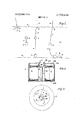
- FIG. 1 is a general schematic showing sequentially the stages of deployment of a sonobuoy assembly embodying features of the invention
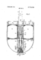
- FIG. 2 is a longitudinal cross sectional view through a preferred embodiment of a sonobuoy mooring unit embodying features of this invention
- FIG. 3 is a partial longitudinal cross sectional view similar to FIG. 2 showing the mooring cable braking means in its cable braking position;
- FIG. 4 is a general schematic plan view of the structure shown in FIG. 3 to illustrate the manner in which the wraps or turns of the mooring cable are formed around the braking member to complete the braking and cable locking action;
- FIG. 5 is a front elevational view of the auxiliary anchor device of the mooring unit of the invention shown in FIG. 8;
- FIG. 6 is an elevational view of the anchor device shown in FIG. 5 looking to the left therein;
- FIG. 7 is a plan section view on the line 7-7 of FIG. 8 of the anchor device.
- FIG. 8 is a vertical sectional view through the anchor device taken on line 8-8 of FIG. 6.
- the sonobuoy assembly 1 of the invention comprising submersible buoy unit 3 and mooring unit 2 is shown at the left hand portion of this drawing figure, after being dropped at the sea surface S.
- the assembly components 2 and 3 after reaching a predetermined depth, detach themselves and separate, the weighted mooring until 2 proceeding downward unwinding a mooring cable 4 from a coil (as described in more detail hereinafter), carried by mooring unit 2.
- the mooring cable 4 is secured to an electric motor-powered winch drum (not shown) carried in submersible buoy unit 3. Proceeding to the right in FIG.
- the next sequential stage shows a float 5 connected to buoy unit 3 by cable 7 and carrying a radio antenna 6 having been. released from buoy unit 3 and moved upwardly to the sea surface S.
- mooring unit 2 has reached. the sea bottom B at which point the mooring cable is locked against further payout and auxiliary anchor device 8 or AA is deployed from the mooring unit.
- the auxiliary anchor is shown deployed to provide additional holding power to maintain the position of mooring unit 2 on the sea bottom against the force of current such as indicated by the arrow.
- the winch drum (not shown) carried by buoy unit 3 has pulled the buoy unit 3 down to its desired operating depth against the weight of mooring unit 2 supplemented by the added drag provided by auxiliary anchor device 8.
- the sonobuoy assembly is then fully deployed for its conventional and normal function of detecting targets and transmitting of information concerning the same to some control point via antenna 6.
- FIG. 2 illustrates a preferred embodiment of the mooring unit of the invention which contains the coil of mooring cable to-be paid out during descent of the mooring unit, the means for braking and stopping cable payout, and the auxiliary anchor device.
- the mooring unit comprises a housing 2 with a cylindrical portion with an open end and an end closed by a hemispherical portion as shown.
- the open end of the housing 2 is closed by a transversely extending wall assembly formed by an outer annular ring member 21A which is secured to housing 2 by suitable means such as machine screws as illustrated, an annular plate member 218, and an inner annular ring member 21C all joined together by suitable means such as welded joints as shown.
- An annular tapered sleeve RS is fitted inside the inner ring member 21C and secured therein by suitable means not shown.
- housing 2 The interior space within housing 2 is divided generally into an upper portion C and a lower portion generally hemispherical in shape by a transverse wall assembly formed by brackets 22A welded to housing 2 and annular plate member 22B attached to the brackets by suitable means such as the machine screws shown.
- a cylindrical wall member 22C is mounted in the lower portion of housing 2 with its axis aligned and concentric with the axis of housing 2, its upper end portion being secured to annular plate 228 as shown by suitable means such as welding and its lower end secured by similar suitable means to the hemispherical end portion of housing 2.
- the lower portion of housing 2 surrounding cylindrical wall member 22C is filled with a suitable ballast or weight such as cast lead to cause rapid descent of the mooring unit and good mooring characteristics when the mooring unit is on the sea bottom.
- annular retaining ring member 23 is secured by threaded engagement with housing 2 and the interior of cylindrical wall member 22C as shown.
- Retaining ring member-23 supports an annular element 24 formed of a suitable deformable material such as a polystyrene foam.
- Deformable element 24 normally supports a thick-walled sleeve or inertia weight member 25.
- a retaining cylinder element 26 Positioned inside sleeve or inertia weight member 25 is a retaining cylinder element 26 supported by and secured at its lower end to retaining ring member 23 by suitable means such as welding.
- a cross pin element 28 is supported by tight frictional engagement in diametrically opposed holes in retaining cylinder26.
- a movable cable braking assembly is mounted within the upper portion of retaining cylinder 26 above cross pin element 28, and consists of a tapered ram head member 29 secured to the upper end of hollow ram shaft 27 by locking pin 31 as shown, and compression spring 40 acting between upper pin 31 and lower pin 28 to urge ram shaft 27 and its ram head member 29 upwardly.
- the tapered ram head member 29 substantially matches the tapered interior of sleeve RS and is provided with an outercoating or layer of lead 30.
- both the main portion of ram head member 29 and sleeve RS are formed of aluminum.
- ram shaft 27 and its ram head member 29 are prevented from moving upwardly by the latching or detent action'of a set of ball elements Bl carried in openings in retaining cylinder 26 and forced radially in wardly by the interior surface of inertia weight member or cylinder 25 into engagement with an annular groove G1 on the exterior surface of ram shaft 27.
- An expellable auxiliary anchor device AA is supported internally in retaining cylinder 26 just below retaining pin 28 and consists of the following parts (referring to FIGS. 5-8 in addition to FIG. 2), an annular base member 53 which is attached by two axially extending side bar elements 54 to a flat cylindrical end element 51. End element 51 is provided with two projecting lugs 60 and 61 in which is mounted a transverse shaft element 62.
- Two pivoted anchor fluke members are mounted on either side of side bars 54, each fluke member having the configuration of a half (longitudinally divided) hollow cylinder with one end closed as shown best in FIGS. 5-8.
- the cylindrical walls 52A and 52B of the fluke members are provided with transversely extending wall portions A and 70B respectively.
- Each transversely extending wall portion 70A and 70B is provided with two brackets 56, 57, 58, and 59 which are rotatably secured to transverse shaft element 62.
- a torsion spring 63 is secured at each end thereof to one of the fluke members by suitable means such as brazing or welding and the spring extends around shaft 62 as shown and urges the fluke elements toward the dashed line positions shown in FIGS. 7 and 8.
- a length of cable 83 is secured at one end to cross pin 28 and at the other end to shaft 62 to secure the auxiliary anchor device to the mooring unit assembly.
- the auxiliary anchor device In normal position of the mooring unit parts, the auxiliary anchor device is prevented from being expelled from cylinder 26 and mooring unit housing by the latching or detent action of a set of ball elements B2 carried in openings in retaining cylinder 26 and forced radially inwardly by the interior surface of inertia weight member or cylinder 25 into engagement with an annular groove G2 on the exterior of annular base element 53 of the auxiliary anchor device AA.
- An annular coil of mooring cable 4 is contained within the upper portion C of housing 2 as shown, preferably arranged for cable payout by unwinding from its central interior portion with the cable moving outwardly through the tapered opening RSO in sleeve member RS and describing the path shown by the arrows D and dashed lines of FIG. 2 during payout. Payout of the cable 4 occurs after separation of mooring unit 2 from buoy unit 3 during descent of the mooring unit 2 to the sea bottom, with the parts of the mooring unit assembly in positions shown in FIG. 2 and the cable moving outwardly through tapered passageway RSO as shown.
- inertia weight member IW being unrestrained except for the engagement of deformable member 24, continues to move in a downward direction deforming or crushing member 24 to the point where the upper end of member 24 clears ball elements B1 and groove G1 which releases rarn shaft 27 and ram head member 29 for upward movement into engagement with conical opening R80 and cable 4.
- enlarged interior poriton A of inertia weight member 25 becomes aligned with ball elements B2 and groove G2 which releases the auxiliary anchor device AA for expulsion from housing 2 by spring 50.
- the pivoted anchor fluke elements 52A and 52B swing outwardly under the urging of spring element 63 into operative sea bottom-engaging positions to assist in holding the mooring unit in position.
- An improved air-launched sonobuoy assembly comprising in combination:
- a main submersible buoy unit releasably containing an antenna float with a transmitting antenna secured thereto;
- a weighted non-buoyant mooring unit releasably secured to said buoy unit, said mooring unit provided with a releasable auxiliary anchor device connected thereto by a length of anchor cable, said submersible buoy unit connected to said antenna float by a length of cable, and to said mooring unit by a variable length of cable, said antenna float and said mooring unit constructed and arranged to separate from said main submersible buoy unit when a predetermined depth has been reached after the assembly has been dropped int-o the sea, said mooring unit comprising structure defining a first chamber for enclosing a coil of mooring cable having one end thereof attached to said submersible buoy unit, said structure further defining an outlet passageway for said first chamber to permit payout movement of the mooring cable therethrough, said mooring unit further comprising a cable braking and locking means cooperating with said cable and said passageway and movable between a first position spaced from said cable and said passageway and a second position in
- a second chamber constructed and arranged to releasably contain said auxiliary anchor device connected by a cable to said structure, expelling means cooperating with said anchor device for moving said anchor device out of said second chamber into operative anchoring position outside said chamber, a second latch mechanism cooperating with said expelling means to maintain said expelling means in inoperative condition and prevent movement of said anchor device from said second chamber, said inertia means cooperating with said second latch mechanism to render said expelling means operative to expel the anchor device from said second chamber upon impact of said mooring unit against the sea bottom.
Landscapes
- Physics & Mathematics (AREA)
- Engineering & Computer Science (AREA)
- Acoustics & Sound (AREA)
- Multimedia (AREA)
- Farming Of Fish And Shellfish (AREA)
Abstract
An air-dropped sonobuoy assembly comprising a weighted mooring unit, a submergible buoy carrying hydrophones, and a float with a radio antenna; the mooring unit being separable from the other elements (after reaching a given depth when dropped in the sea) for mooring cable payout and rapid descent to the sea bottom where further cable payout is prevented. At this point a mooring cable-winch in the buoy reels in the cable to lower the buoy to desired operating depth. The specific mooring cable securing mechanism permits rapid payout of cable until the mooring unit bottoms and then quickly locks the cable against further payout so the winch can pull the buoy down to desired depth against the weight of the mooring unit. The mooring unit also contains an auxiliary anchor device which is deployed upon bottoming of the mooring unit.
Description
United States Patent Snyder Nov. 13, 1973 SONOBUOY MOORING UNIT {57] ABSTRACT [75] Inventor: Robert M. Snyder, Jupiter, Fla.
[73] Assignee: The United States of America as An aipdropped sonobuoy assembly comprising a represented the secretary of the weighted mooring unit, a submergible buoy carrying Navy washmgton hydrophones, and a float with a radio antenna; the 2 Filed; July 2 97 mooring unit being separable from the other elements (after reaching a given depth when dropped in the 2 A 2 l 1] 74,551 sea) for mooring cable payout and rapid descent to the sea bottom where further cable payout is pre- 52 us. (:1. 340/2, 102/13 vemed- At this P a mooring: cable-Winch in the [51] Int. Cl. G0ls 1/72 buoy reels in the cable to lower the y to desired [58] Field of Search 9/8, 83; 340/2, Operating depth The specific mooring cable Securing 340/7; 102/13 14, 1Q mechanism permits rapid payout of cable until the mooring unit bottoms and then quickly locks the cable 5 References Cied against further payout so the winch can pull the buoy UNITED STATES PATENTS down to desired depth against the weight of the mooring unit. The mooring unit also contains an auxiliary 5:32 3; anchor device which is deployed upon bottoming of 3:631:550 1/1972 Bullen 9/8 R the Primary Examiner-Samuel W. Engle AttorneyR. S. Sciascia et al. 3 Claims, 8 Drawing Figures SONOBUOY MOORING UNIT STATEMENT OF GOVERNMENT INTEREST The invention described herein may be manufactured and used by or for the Government of the United States of America for governmental purposes without the payment of any royalties thereon or therefor.
BACKGROUND OF THE INVENTION This invention relates generally to the field of airlaunched moored sonobuoy systems and more specifically to an improved mooring unit for such systems having specific cable locking features and specific auxiliary anchoring features which are desirable and advantageous.
Many sonobuoy systems are known in the art; however the mooring arrangements disclosed appear to be of complicated impractical designs susceptible to many problems in their production, storage, and use, especially where the systems are to be used in very deep waters. The prior art mooring systems do not appear to have made suitable provision for securing the system in place against storage current forces at great depths. With the areas of submarine warfare and submarine detection increasing in significance and activity these prior art shortcomings are significant and serious.
SUMMARY OF THE INVENTION The shortcomings and deficiencies of the prior art systems and devices have been overcome and the hereinafter-mentioned objects of the invention have been achieved by an improved air-launched sonobuoy assembly comprising in combination: a main submersible buoy unit releasably containing an antenna float with a transmitting antenna secured thereto; a weighted non-buoyant mooring unit releasably secured to said buoy unit, said mooring unit provided with a releasable auxiliary anchor device connected thereto by a length of anchor cable, said submersible buoy unit connected to said antenna float by a length of cable, and to said mooring unit by a variable length of cable, said antenna float and said mooring unit constructed and arranged to separate from said main submersible buoy unit when a predetermined depth has been reached after the assembly has been dropped into the sea, said mooring unit comprising structure defining a first chamber for enclosing a coil of mooring cable having one end thereof attached to said submersible buoy unit, said structure further defining an outlet passageway for said first chamber to permit payout movement of the mooring cable therethrough, said mooring unit further comprising a cable braking and locking means cooperating with said cable and said passageway and movable between a first position spaced from said cable and said passageway and a second position in operative braking engagement with said cable and said passageway to stop payout movement of said mooring cable from said chamber through said passageway, drive means urging said cable braking and locking means towards its second position, a first latch mechanism cooperating with said cable braking and locking means and operative to releasably hold said braking and locking means in said first position, an inertia means cooperating with said latch means and actuatable by impact of said mooring unit against the sea bottom to render said first latch means inoperative to hold said braking and locking means in its first position and thus to release the braking and locking means to move to its second position to engage the cable and stop payout of the cable.
STATEMENT OF OBJECTS OF THE INVENTION It is an object of this invention to provide an improved sonobuoy mooring unit of a simple, rugged, and effective design which performs well at great depths and under conditions of strong sea currents.
It is a further object of the invention to provide such improved mooring units which are relatively simple and economical to produce, store, and use, and which are highly reliable in operation after long storage periods.
Other objects, advantages, and novel features of the invention will become apparent from the following detailed description of the invention and the claims when considered in conjunction with the accompanying drawings wherein:
BRIEF DESCRIPTION OF THE DRAWING FIG. 1 is a general schematic showing sequentially the stages of deployment of a sonobuoy assembly embodying features of the invention;
FIG. 2 is a longitudinal cross sectional view through a preferred embodiment of a sonobuoy mooring unit embodying features of this invention;
FIG. 3 is a partial longitudinal cross sectional view similar to FIG. 2 showing the mooring cable braking means in its cable braking position;
FIG. 4 is a general schematic plan view of the structure shown in FIG. 3 to illustrate the manner in which the wraps or turns of the mooring cable are formed around the braking member to complete the braking and cable locking action;
FIG. 5 is a front elevational view of the auxiliary anchor device of the mooring unit of the invention shown in FIG. 8;
FIG. 6 is an elevational view of the anchor device shown in FIG. 5 looking to the left therein;
FIG. 7 is a plan section view on the line 7-7 of FIG. 8 of the anchor device; and
FIG. 8 is a vertical sectional view through the anchor device taken on line 8-8 of FIG. 6.
DESCRIPTION OF THE PREFERRED EMBODIMENT In FIG. 1, the sonobuoy assembly 1 of the invention, comprising submersible buoy unit 3 and mooring unit 2 is shown at the left hand portion of this drawing figure, after being dropped at the sea surface S. In the next portion of this figure, the assembly components 2 and 3, after reaching a predetermined depth, detach themselves and separate, the weighted mooring until 2 proceeding downward unwinding a mooring cable 4 from a coil (as described in more detail hereinafter), carried by mooring unit 2. The mooring cable 4 is secured to an electric motor-powered winch drum (not shown) carried in submersible buoy unit 3. Proceeding to the right in FIG. 1 the next sequential stage shows a float 5 connected to buoy unit 3 by cable 7 and carrying a radio antenna 6 having been. released from buoy unit 3 and moved upwardly to the sea surface S. In addition, mooring unit 2 has reached. the sea bottom B at which point the mooring cable is locked against further payout and auxiliary anchor device 8 or AA is deployed from the mooring unit. In the right hand view of FIG. 1, the auxiliary anchor is shown deployed to provide additional holding power to maintain the position of mooring unit 2 on the sea bottom against the force of current such as indicated by the arrow. Also at this point the winch drum (not shown) carried by buoy unit 3 has pulled the buoy unit 3 down to its desired operating depth against the weight of mooring unit 2 supplemented by the added drag provided by auxiliary anchor device 8. The sonobuoy assembly is then fully deployed for its conventional and normal function of detecting targets and transmitting of information concerning the same to some control point via antenna 6.
FIG. 2 illustrates a preferred embodiment of the mooring unit of the invention which contains the coil of mooring cable to-be paid out during descent of the mooring unit, the means for braking and stopping cable payout, and the auxiliary anchor device. The mooring unit comprises a housing 2 with a cylindrical portion with an open end and an end closed by a hemispherical portion as shown. The open end of the housing 2 is closed by a transversely extending wall assembly formed by an outer annular ring member 21A which is secured to housing 2 by suitable means such as machine screws as illustrated, an annular plate member 218, and an inner annular ring member 21C all joined together by suitable means such as welded joints as shown. An annular tapered sleeve RS is fitted inside the inner ring member 21C and secured therein by suitable means not shown.
The interior space within housing 2 is divided generally into an upper portion C and a lower portion generally hemispherical in shape by a transverse wall assembly formed by brackets 22A welded to housing 2 and annular plate member 22B attached to the brackets by suitable means such as the machine screws shown. A cylindrical wall member 22C is mounted in the lower portion of housing 2 with its axis aligned and concentric with the axis of housing 2, its upper end portion being secured to annular plate 228 as shown by suitable means such as welding and its lower end secured by similar suitable means to the hemispherical end portion of housing 2. Preferably the lower portion of housing 2 surrounding cylindrical wall member 22C is filled with a suitable ballast or weight such as cast lead to cause rapid descent of the mooring unit and good mooring characteristics when the mooring unit is on the sea bottom.
An annular retaining ring member 23 is secured by threaded engagement with housing 2 and the interior of cylindrical wall member 22C as shown. Retaining ring member-23 supports an annular element 24 formed of a suitable deformable material such as a polystyrene foam. Deformable element 24 normally supports a thick-walled sleeve or inertia weight member 25. Positioned inside sleeve or inertia weight member 25 is a retaining cylinder element 26 supported by and secured at its lower end to retaining ring member 23 by suitable means such as welding. A cross pin element 28 is supported by tight frictional engagement in diametrically opposed holes in retaining cylinder26. A movable cable braking assembly is mounted within the upper portion of retaining cylinder 26 above cross pin element 28, and consists of a tapered ram head member 29 secured to the upper end of hollow ram shaft 27 by locking pin 31 as shown, and compression spring 40 acting between upper pin 31 and lower pin 28 to urge ram shaft 27 and its ram head member 29 upwardly. The tapered ram head member 29 substantially matches the tapered interior of sleeve RS and is provided with an outercoating or layer of lead 30. Preferably, both the main portion of ram head member 29 and sleeve RS are formed of aluminum.
In normal positions and condition of the mooring unit parts, ram shaft 27 and its ram head member 29 are prevented from moving upwardly by the latching or detent action'of a set of ball elements Bl carried in openings in retaining cylinder 26 and forced radially in wardly by the interior surface of inertia weight member or cylinder 25 into engagement with an annular groove G1 on the exterior surface of ram shaft 27.
An expellable auxiliary anchor device AA is supported internally in retaining cylinder 26 just below retaining pin 28 and consists of the following parts (referring to FIGS. 5-8 in addition to FIG. 2), an annular base member 53 which is attached by two axially extending side bar elements 54 to a flat cylindrical end element 51. End element 51 is provided with two projecting lugs 60 and 61 in which is mounted a transverse shaft element 62. Two pivoted anchor fluke members are mounted on either side of side bars 54, each fluke member having the configuration of a half (longitudinally divided) hollow cylinder with one end closed as shown best in FIGS. 5-8. The cylindrical walls 52A and 52B of the fluke members are provided with transversely extending wall portions A and 70B respectively. Each transversely extending wall portion 70A and 70B is provided with two brackets 56, 57, 58, and 59 which are rotatably secured to transverse shaft element 62. A torsion spring 63 is secured at each end thereof to one of the fluke members by suitable means such as brazing or welding and the spring extends around shaft 62 as shown and urges the fluke elements toward the dashed line positions shown in FIGS. 7 and 8. A length of cable 83 is secured at one end to cross pin 28 and at the other end to shaft 62 to secure the auxiliary anchor device to the mooring unit assembly.
A compression spring 50 acting between cross pin 28 and end wall portions 70A and 70B of the fluke members urges the auxiliary anchor device out of retaining cylinder 26 and the mooring unit housing 2. In normal position of the mooring unit parts, the auxiliary anchor device is prevented from being expelled from cylinder 26 and mooring unit housing by the latching or detent action of a set of ball elements B2 carried in openings in retaining cylinder 26 and forced radially inwardly by the interior surface of inertia weight member or cylinder 25 into engagement with an annular groove G2 on the exterior of annular base element 53 of the auxiliary anchor device AA.
An annular coil of mooring cable 4 is contained within the upper portion C of housing 2 as shown, preferably arranged for cable payout by unwinding from its central interior portion with the cable moving outwardly through the tapered opening RSO in sleeve member RS and describing the path shown by the arrows D and dashed lines of FIG. 2 during payout. Payout of the cable 4 occurs after separation of mooring unit 2 from buoy unit 3 during descent of the mooring unit 2 to the sea bottom, with the parts of the mooring unit assembly in positions shown in FIG. 2 and the cable moving outwardly through tapered passageway RSO as shown.
When mooring unit 2 strikes the sea bottom, inertia weight member IW, being unrestrained except for the engagement of deformable member 24, continues to move in a downward direction deforming or crushing member 24 to the point where the upper end of member 24 clears ball elements B1 and groove G1 which releases rarn shaft 27 and ram head member 29 for upward movement into engagement with conical opening R80 and cable 4. At this same point enlarged interior poriton A of inertia weight member 25 becomes aligned with ball elements B2 and groove G2 which releases the auxiliary anchor device AA for expulsion from housing 2 by spring 50. As the auxiliary anchor device moves clear of the cylindrical recess in the housing 2, the pivoted anchor fluke elements 52A and 52B swing outwardly under the urging of spring element 63 into operative sea bottom-engaging positions to assist in holding the mooring unit in position.
Referring again to upward movement of tapered ram head member 29 into engagement with tapered opening RSO and cable 4 it will be seen that a wedging action occurs which first restrains the outwardly mooring cable 4 against the rotating circular motion at the open ing RSO in the direction shown by the arrows D and then applies a braking force which at first is insufficient to stop the outward cable movement. Then for a brief period an action accurs, as shown in FIG. 4, in which the outwardly moving cable passes through a fixed point of engagement between members RS and while still undergoing a circular unwinding motion at the inside portion of the annular coil in the upper portion of housing 2. The force continuing outward cable movement is caused by the buoyancy of unit 3 and/or sea current forces. Since the point at which the cable is engaged by members RS and 3 is fixed or moving relatively slowly as compared with the rate of unwinding at the inner portion of the annular coil, the cable beneath the ram head 29 wraps itself about ram shaft member 27 in a series of turns, as illustrated in FIGS. 3 and 4, to the point at which the frictional drag increases, pulls ram head 29 up into sufficiently tight engagement with member RS and the cable 4 to positively stop and lock cable 4 against further outward movement. For very strong forces tending to pull the cable out through the point of engagement between members 29 and RS, a second layer of overlapping cable wraps may be required and will inherently be formed on shaft 27 which advantageously provides greatly increased drag or snubbing action.
As previously mentioned, secure locking of the cable 4 against outward movement then not only provides secure mooring of unit 3 but permits the winch drum in buoy unit 3 to pull unit 3 down to desired operating depth against the weight and drag of mooring unit 2 and anchor device AA. This winch feature is not described in detail since it forms no part of the present invention.
It is believed clear from the above description and discussion that applicant has provided an improved mooring unit for a sonobuoy assembly in accordance with the objects of the invention.
What is claimed is:
1. An improved air-launched sonobuoy assembly comprising in combination:
a main submersible buoy unit releasably containing an antenna float with a transmitting antenna secured thereto;
a weighted non-buoyant mooring unit releasably secured to said buoy unit, said mooring unit provided with a releasable auxiliary anchor device connected thereto by a length of anchor cable, said submersible buoy unit connected to said antenna float by a length of cable, and to said mooring unit by a variable length of cable, said antenna float and said mooring unit constructed and arranged to separate from said main submersible buoy unit when a predetermined depth has been reached after the assembly has been dropped int-o the sea, said mooring unit comprising structure defining a first chamber for enclosing a coil of mooring cable having one end thereof attached to said submersible buoy unit, said structure further defining an outlet passageway for said first chamber to permit payout movement of the mooring cable therethrough, said mooring unit further comprising a cable braking and locking means cooperating with said cable and said passageway and movable between a first position spaced from said cable and said passageway and a second position in operative braking engagement with said cable and said passageway to stop payout movement of said mooring cable from said chamber through said passageway, drive means urging said cable braking and locking means towards its second position, a first latch mechanism cooperating with said cable braking and locking means and operative to releasably hold said braking and locking means in said first position, an inertia means cooperating with said latch means and actuatable by impact of said mooring unit against the sea bottom to render said first latch means inoperative to hold said braking and locking means in its first position and thus to release the braking and locking means to move to its second position to engage the cable and stop payout of the cable.
2. The improved assembly of claim 1 in which said mooring unit further comprises:
structure defining a second chamber, said chamber constructed and arranged to releasably contain said auxiliary anchor device connected by a cable to said structure, expelling means cooperating with said anchor device for moving said anchor device out of said second chamber into operative anchoring position outside said chamber, a second latch mechanism cooperating with said expelling means to maintain said expelling means in inoperative condition and prevent movement of said anchor device from said second chamber, said inertia means cooperating with said second latch mechanism to render said expelling means operative to expel the anchor device from said second chamber upon impact of said mooring unit against the sea bottom.
3. The improved assembly of claim 2 in which said means urging said braking and locking element toward its second position, and said expelling means comprise spring devices.
Claims (3)
1. An improved air-launched sonobuoy assembly comprising in combination: a main submersible buoy unit releasably containing an antenna float with a transmitting antenna secured thereto; a weighted non-buoyant mooring unit releasably secured to said buoy unit, said mooring unit provided with a releasable auxiliary anchor device connected thereto by a length of anchor cable, said submersible buoy unit connected to said antenna float by a length of cable, and to said mooring unit by a variable length of cable, said antenna float and said mooring unit constructed and arranged to separate from said main submersible buoy unit when a predetermined depth has been reached after the assembly has been dropped into the sea, said mooring unit comprising structure defining a first chamber for enclosing a coil of mooring cable having one end thereof attached to said submersible buoy unit, said structure further defining an outlet passageway for said first chamber to permit payout movement of the mooring cable therethrough, said mooring unit further comprising a cable braking and locking means cooperating with said cable and said passageway and movable between a first position spaced from said cable and said passageway and a second position in operative braking engagement with said cable and said passageway to stop payout movement of said mooring cable from said chamber through said passageway, drive means urging said cable braking and locking means towards its second position, a first latch mechanism cooperating with said cable braking and locking means and operative to releasably hold said braking and locking means in said first position, an inertia means cooperating with said latch means and actuatable by impact of said mooring unit against the sea bottom to render said first latch means inoperative to hold said braking and locking means in its first position and thus to release the braking and locking means to move to its second position to engage the cable and stop payout of the cable.
2. The improved assembly of claim 1 in which said mooring unit further comprises: structure defining a second chamber, said chamber constructed and arranged to releasably contain said auxiliary anchor device connected by a cable to said structure, expelling means cooperating with said anchor device for moving Said anchor device out of said second chamber into operative anchoring position outside said chamber, a second latch mechanism cooperating with said expelling means to maintain said expelling means in inoperative condition and prevent movement of said anchor device from said second chamber, said inertia means cooperating with said second latch mechanism to render said expelling means operative to expel the anchor device from said second chamber upon impact of said mooring unit against the sea bottom.
3. The improved assembly of claim 2 in which said means urging said braking and locking element toward its second position, and said expelling means comprise spring devices.
Applications Claiming Priority (1)
| Application Number | Priority Date | Filing Date | Title |
|---|---|---|---|
| US27455172A | 1972-07-24 | 1972-07-24 |
Publications (1)
| Publication Number | Publication Date |
|---|---|
| US3772639A true US3772639A (en) | 1973-11-13 |
Family
ID=23048672
Family Applications (1)
| Application Number | Title | Priority Date | Filing Date |
|---|---|---|---|
| US00274551A Expired - Lifetime US3772639A (en) | 1972-07-24 | 1972-07-24 | Sonobuoy mooring unit |
Country Status (1)
| Country | Link |
|---|---|
| US (1) | US3772639A (en) |
Cited By (12)
| Publication number | Priority date | Publication date | Assignee | Title |
|---|---|---|---|---|
| US4313381A (en) * | 1979-11-26 | 1982-02-02 | The United States Of America As Represented By The Secretary Of The Navy | Mooring system |
| US4358834A (en) * | 1981-04-16 | 1982-11-09 | The United States Of America As Represented By The Secretary Of The Navy | Self-deploying buoy system |
| US4516227A (en) * | 1981-12-04 | 1985-05-07 | Marathon Oil Company | Subocean bottom explosive seismic system |
| US4535430A (en) * | 1982-07-07 | 1985-08-13 | Cochrane Subsea Acoustics, Inc. | Subsea acoustic relocation system |
| US6880290B2 (en) * | 2002-09-09 | 2005-04-19 | Patrick Mahoney | Fishing gear recovery device |
| US20080121748A1 (en) * | 2006-08-25 | 2008-05-29 | Lockheed Martin Corporation | Passively-actuated Lanyard Clamp |
| WO2008138951A1 (en) * | 2007-05-15 | 2008-11-20 | Cggveritas Services Sa | A seismic data acquisition module, a seismic prospection system including such a module, and a method of installing such a system |
| US20090269709A1 (en) * | 2008-04-28 | 2009-10-29 | Her Majesty In Right Of Canada As Represented By The Minister Of Fisheries And Oceans | Communication float |
| US20100000463A1 (en) * | 2004-12-08 | 2010-01-07 | Lockheed Martin Corporation | Waterborne munitions system |
| WO2012001646A1 (en) * | 2010-07-01 | 2012-01-05 | Mahala Power Co Ltd | Wave power assembly |
| US8274861B1 (en) * | 2009-12-08 | 2012-09-25 | The United States Of America As Represented By The Secretary Of The Navy | Underwater network having buoyancy compensation and anchoring systems |
| CN110307896A (en) * | 2019-06-12 | 2019-10-08 | 中国舰船研究设计中心 | A kind of characteristics of ship underwater radiation noise measurement hydrophone suspension and lay method |
Citations (3)
| Publication number | Priority date | Publication date | Assignee | Title |
|---|---|---|---|---|
| US2422337A (en) * | 1940-04-19 | 1947-06-17 | Chilowsky Constantin | Submarine detecting buoy |
| US3309649A (en) * | 1964-03-26 | 1967-03-14 | Sanders Associates Inc | Sonobuoy with depth selection capabilities |
| US3631550A (en) * | 1968-07-16 | 1972-01-04 | Emi Ltd | Mooring devices |
-
1972
- 1972-07-24 US US00274551A patent/US3772639A/en not_active Expired - Lifetime
Patent Citations (3)
| Publication number | Priority date | Publication date | Assignee | Title |
|---|---|---|---|---|
| US2422337A (en) * | 1940-04-19 | 1947-06-17 | Chilowsky Constantin | Submarine detecting buoy |
| US3309649A (en) * | 1964-03-26 | 1967-03-14 | Sanders Associates Inc | Sonobuoy with depth selection capabilities |
| US3631550A (en) * | 1968-07-16 | 1972-01-04 | Emi Ltd | Mooring devices |
Cited By (18)
| Publication number | Priority date | Publication date | Assignee | Title |
|---|---|---|---|---|
| US4313381A (en) * | 1979-11-26 | 1982-02-02 | The United States Of America As Represented By The Secretary Of The Navy | Mooring system |
| US4358834A (en) * | 1981-04-16 | 1982-11-09 | The United States Of America As Represented By The Secretary Of The Navy | Self-deploying buoy system |
| US4516227A (en) * | 1981-12-04 | 1985-05-07 | Marathon Oil Company | Subocean bottom explosive seismic system |
| US4535430A (en) * | 1982-07-07 | 1985-08-13 | Cochrane Subsea Acoustics, Inc. | Subsea acoustic relocation system |
| US6880290B2 (en) * | 2002-09-09 | 2005-04-19 | Patrick Mahoney | Fishing gear recovery device |
| US20100000463A1 (en) * | 2004-12-08 | 2010-01-07 | Lockheed Martin Corporation | Waterborne munitions system |
| US8596181B2 (en) * | 2004-12-08 | 2013-12-03 | Lockheed Martin Corporation | Waterborne munitions system |
| US8096256B2 (en) * | 2006-08-25 | 2012-01-17 | Lockheed Martin Corporation | Passively-actuated lanyard clamp |
| US20080121748A1 (en) * | 2006-08-25 | 2008-05-29 | Lockheed Martin Corporation | Passively-actuated Lanyard Clamp |
| FR2916281A1 (en) * | 2007-05-15 | 2008-11-21 | Cybernetix Sa | SEISMIC DATA ACQUISITION MODULE, SEISMIC PROSPECTION SYSTEM COMPRISING SUCH A MODULE AND METHOD OF INSTALLING SUCH A SYSTEM. |
| WO2008138951A1 (en) * | 2007-05-15 | 2008-11-20 | Cggveritas Services Sa | A seismic data acquisition module, a seismic prospection system including such a module, and a method of installing such a system |
| US20090269709A1 (en) * | 2008-04-28 | 2009-10-29 | Her Majesty In Right Of Canada As Represented By The Minister Of Fisheries And Oceans | Communication float |
| US7874886B2 (en) * | 2008-04-28 | 2011-01-25 | Her Majesty in the right of Canada as represented by the Department of Fisheries and Oceans | Communication float |
| US8274861B1 (en) * | 2009-12-08 | 2012-09-25 | The United States Of America As Represented By The Secretary Of The Navy | Underwater network having buoyancy compensation and anchoring systems |
| WO2012001646A1 (en) * | 2010-07-01 | 2012-01-05 | Mahala Power Co Ltd | Wave power assembly |
| CN102959235A (en) * | 2010-07-01 | 2013-03-06 | 马哈拉电力有限公司 | Wave power assembly |
| US20130199171A1 (en) * | 2010-07-01 | 2013-08-08 | Mahala Power Co. Ltd. | Wave Power Assembly |
| CN110307896A (en) * | 2019-06-12 | 2019-10-08 | 中国舰船研究设计中心 | A kind of characteristics of ship underwater radiation noise measurement hydrophone suspension and lay method |
Similar Documents
| Publication | Publication Date | Title |
|---|---|---|
| US3772639A (en) | Sonobuoy mooring unit | |
| CN108454783B (en) | Underwater platform cable throwing device with buoy | |
| US6021731A (en) | Ballast system for underwater vehicle | |
| JP5323166B2 (en) | submarine | |
| US4189703A (en) | System for deploying a sensor array from transiting vessel | |
| US8096257B2 (en) | Emergency encapsulated lift system | |
| US3921120A (en) | Float actuated release mechanism | |
| WO2004071864A2 (en) | Deployable and autonomous mooring system | |
| US4631956A (en) | Air deployed oceanographic mooring | |
| US4651834A (en) | Ice penetrating method and apparatus | |
| US3291092A (en) | Mooring apparatus | |
| US3657752A (en) | Locator devices | |
| RU2042570C1 (en) | Method and device for breaking ice by means of submersible water craft | |
| US4972776A (en) | Submarine minesweeper | |
| US4654832A (en) | Sonobuoy retaining and release apparatus | |
| US2993461A (en) | Embedment anchor | |
| US3788255A (en) | Expendable submarine receiving antenna | |
| US4029233A (en) | Sonobuoy retainer plate | |
| EP4054928B1 (en) | Parachute sea anchor | |
| US3121239A (en) | Marker buoy release mechanism | |
| US4096818A (en) | Drogue type deceleration device | |
| US3262412A (en) | Pad-lock anchor system | |
| US3709148A (en) | Drill mine | |
| US3487485A (en) | Deep ocean buoy assembly | |
| RU2029708C1 (en) | Buoy system |