US3771071A - Adjustable equalizer for wide-band transmission system - Google Patents
Adjustable equalizer for wide-band transmission system Download PDFInfo
- Publication number
- US3771071A US3771071A US00244719A US24471972A US3771071A US 3771071 A US3771071 A US 3771071A US 00244719 A US00244719 A US 00244719A US 24471972 A US24471972 A US 24471972A US 3771071 A US3771071 A US 3771071A
- Authority
- US
- United States
- Prior art keywords
- equalizer
- coupler
- frequency
- network
- voltage
- Prior art date
- Legal status (The legal status is an assumption and is not a legal conclusion. Google has not performed a legal analysis and makes no representation as to the accuracy of the status listed.)
- Expired - Lifetime
Links
- 230000005540 biological transmission Effects 0.000 title abstract description 7
- 238000004804 winding Methods 0.000 claims abstract description 7
- 230000008878 coupling Effects 0.000 claims description 5
- 238000010168 coupling process Methods 0.000 claims description 5
- 238000005859 coupling reaction Methods 0.000 claims description 5
- 230000000694 effects Effects 0.000 description 3
- 239000000470 constituent Substances 0.000 description 2
- 241001481828 Glyptocephalus cynoglossus Species 0.000 description 1
- 230000002238 attenuated effect Effects 0.000 description 1
- 239000003990 capacitor Substances 0.000 description 1
- 239000000969 carrier Substances 0.000 description 1
- 230000001447 compensatory effect Effects 0.000 description 1
- 230000000295 complement effect Effects 0.000 description 1
- 238000013016 damping Methods 0.000 description 1
- 238000010586 diagram Methods 0.000 description 1
- 239000011159 matrix material Substances 0.000 description 1
- 230000008447 perception Effects 0.000 description 1
- 230000010363 phase shift Effects 0.000 description 1
- 230000001932 seasonal effect Effects 0.000 description 1
- 230000008054 signal transmission Effects 0.000 description 1
- 230000011664 signaling Effects 0.000 description 1
- 238000011144 upstream manufacturing Methods 0.000 description 1
Images
Classifications
-
- H—ELECTRICITY
- H04—ELECTRIC COMMUNICATION TECHNIQUE
- H04B—TRANSMISSION
- H04B3/00—Line transmission systems
- H04B3/02—Details
- H04B3/04—Control of transmission; Equalising
- H04B3/14—Control of transmission; Equalising characterised by the equalising network used
- H04B3/141—Control of transmission; Equalising characterised by the equalising network used using multiequalisers, e.g. bump, cosine, Bode
Definitions
- An equalizer for a system transmitting a wide band of frequencies comprises a multiplicity of networks con- Apt. 15, 1971 Italy 232l5A/7l nected in parallel between a fi coupler of'low output impedance and a second coupler of low input imped- [52] U.S. Cl. 333/28 R, 333/70 R ance, one of these networks being of the albpassvtype [5 l Int. Cl.
- Each of the adjustable networks comprises a [56] Reterenc-es cued band-pass filter, including the primary winding of an UNITED STATES A S internal transformer, and a polarity-inverting voltage 3,458,8'l6 7/1969 OBrien 333/70 R X divider. v 2,716,733 8/1955 Roark 333/28 R X 2,907,838 10/1959 Ross 333/28 R ux 2.
- snmzurz l ADJUSTABLE EQUALIZER FOR WIDE-BAND TRANSMISSION SYSTEM My present invention relates to an equalizer for a wide-band signaling system, e.g., a system for the transmission of a multiplicity of voice channels on respective carriers by way of a coaxial cable.
- the general object of my present invention is to provide an improved, simplified equalizer designed to satisfy widely varying requirements.
- a more specific object is to provide an equalizer whose basic constituents operate virtually independently in different ranges of the band so that an adjustment of any such constituent does not affect the setting of the others or appreciably alter the attenuation or phase of the frequencies controlled by them.
- the first coupler, upstream of the parallel-connected networks, should have a very low output impedance so as to act as a current source substantially unaffected by any variation in he resistance of the several: branch.
- the, second coupler on the downstream side of the network should have a very low input impedance to act as av complementary current sink.
- each network comprises one or more voltage dividers (e.g. potentiom eters) for the stepwise or continuous adjustment of the effective series resistance of the network and therefore of the compensatory currents passing therethrough, these currents are limited totheassigned sub-band by a frequency-selective pad such as a band-pass filter in cascade with the voltage divider so that the setting of the latter has no appreciable effect upon current of other frequencies in the equalizer output.
- the band-pass filter is essentially a parallel-resonant circuit tuned to the respective midfrequency, this circuit including a capacitance in shunt with an inductance which preferably is constituted by a primary winding of an internal coupling transformer.
- Polarity-inverting circuitry such as a reversing switch associated with the voltage divider enables selection not only of the magntidue but'also of the sign of the compensating current traversing any of the control networks, i.e., a shifting of its phase by 180 relative tozthe corresponding component in the output of the all-pass network.
- the selectecl midfrequencies advantageously are so-called'intersti-tial frequencies lying in the zones between adjoining first frequency spaced channels or channel groups. If one of the control networks should fail for any reason, networks controlling adjoining sub-bands could be returned to encompass the uncontrolled frequency range.
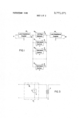
- FIG.'1 is an overall block diagram of an equalizer embodying my invention
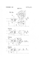
- FIGS. 2a, 2b, 2c and 2d show different embodiments of control networks used in the system of FIG. 1;
- FIG. 3 illustrates in greater detail a frequency selective circuit included in the networks of FIGS. 2a 2d.
- the system shown in FIG. 1 comprises a transmission path 10 extending between a pair of input terminals 11 and a pair of output terminals 12.
- a first lowimpedance coupler 13, energized with a wide band of incoming signal frequencies, works into a large number of networks K K K K connected in parallel between that coupler and a similar low-impedance coupler l4.
- Couplers l3 and 14 are four-terminal networks with a near-zero output impedance and a near-zero input impedance, respectively, thereby effectively decoupling the intervening networks K K from one another.
- Network K is of the all-pass type having a constant transadmittance throughout the overall band; its output current I, encompasses all the frequencies transmitted within that band.
- Networks K K K pass currents I,, I I,, in relatively narrow sub-bands which may be centered on the interstitial frequencies between adjacent channels; each of these latter networks is independently adjustable to enable variation of the magnitude and/or the sign of its output current compensating for excessive or insuffleient attenuation of the corresponding component of I
- FIG. 2a shows a control network.
- K generically representing any of the networks K, K of FIG. 1.
- This network comprises a frequency-selective circuit H, i.e., a band-pass filter centered on a midfrequency f, coupled through a transformer T to a manually settable control cirucit including a pair of resistance chains R, R and a two-level rotary switch 8,, 5,, whose first wiper S, coacts with bank contacts (designated +1, +2, +3 and -l, 2, 3 tied to respective junctions of the two resistance chains; wiper S sweeps two series of interconnected bank contacts B and B respectively tied to resistances R and R.
- a frequency-selective circuit H i.e., a band-pass filter centered on a midfrequency f
- FIG. 2b shows a modified control network K
- switch 5 has been replaced by a double-pole double-throw switch S reversibly connecting the secondary of transformer T across a potentiometer P.
- the magnitude of output current U is thus continuously adjustable with the aid of the potentiometer P whereas its polarity can be selected by means of reversing switch S.
- Another control network K shown in FIG. 20, combines certain features of the preceding two Figures by having a resistance chain R" connected across the secondary of the transformer T, coacting with a singlelevel rotary switch S" whose wiper arm is engageable with any of several bank contacts labeled +3, +2, +1, 0, l 2, 3.
- a network K operates in essentially thesame manner as network K," of FIG. 2c, except that resistance chain R" has been replaced by potentiometer P so that its adjustability is continuous rather than in steps.
- FIG. 3 A representative embodiment of frequency-selective netowrk H, is illustrated in FIG. 3 as comprising an input resisjor R followed by a shunt capacitor C.
- the latter resonates the primary of transformer T at the assigned midfrequencyf so that the shunt impedance of the network is substantially infinite at that frequency.
- Capacitance C may, of course, form part of a more elaborate band-pass filter having a definite cutoff frequency at the upper and lower limits of the assigned range.
- Resistors R and R serve as decoupling resistances.
- each of the networks K, K is assumed to control only its own subband centered on frequency f a more precise analysis taking into account the residual effect upon the other sub-bands establishes adamping factor 5,, introduced by the equalizer for any given frequency f,, as
- the system herein disclosed is particularly suitable for the adjustment of multichannel telecommunication facilities to seasonal variations of transmission characteristics. In a practical realization, up to 2,700 channels could be accommodated.
- each of said control networks comprises voltage-divider means for varying the magnitudes of the currents passed thereby and polarity-inverting circuitry for selectively shifting the phase of the passed currents by 3.
- each of said control networks includes a frequency-selective circuit, tuned to the respective midfrequency, in cascade with said voltage-divider means.
- each of said control networks includes a coupling transformer between said frequency-selective circuit and said voltage-divider means.
- said frequency-selective circuit comprises a shunt capacitance resonating a primary winding of said transformer at the respective midfrequency.
Landscapes
- Engineering & Computer Science (AREA)
- Computer Networks & Wireless Communication (AREA)
- Signal Processing (AREA)
- Filters And Equalizers (AREA)
- Networks Using Active Elements (AREA)
Applications Claiming Priority (1)
| Application Number | Priority Date | Filing Date | Title |
|---|---|---|---|
| IT2321571 | 1971-04-15 |
Publications (1)
| Publication Number | Publication Date |
|---|---|
| US3771071A true US3771071A (en) | 1973-11-06 |
Family
ID=11204963
Family Applications (1)
| Application Number | Title | Priority Date | Filing Date |
|---|---|---|---|
| US00244719A Expired - Lifetime US3771071A (en) | 1971-04-15 | 1972-04-17 | Adjustable equalizer for wide-band transmission system |
Country Status (5)
| Country | Link |
|---|---|
| US (1) | US3771071A (enExample) |
| DE (1) | DE2217355A1 (enExample) |
| FR (1) | FR2133551B1 (enExample) |
| GB (1) | GB1358860A (enExample) |
| SE (1) | SE383815B (enExample) |
Cited By (3)
| Publication number | Priority date | Publication date | Assignee | Title |
|---|---|---|---|---|
| DE2454631A1 (de) * | 1973-11-19 | 1975-05-22 | Dolby Laboratories Inc | Entzerrerschaltung |
| US4271398A (en) * | 1978-11-30 | 1981-06-02 | Pioneer Electronic Corporation | Tone control device |
| US20240031526A1 (en) * | 2022-07-25 | 2024-01-25 | Arris Enterprises Llc | Electronic tunable cable simulator |
Citations (3)
| Publication number | Priority date | Publication date | Assignee | Title |
|---|---|---|---|---|
| US2716733A (en) * | 1950-05-10 | 1955-08-30 | Exxon Research Engineering Co | Variable bandwidth band-pass filter |
| US2907838A (en) * | 1957-02-14 | 1959-10-06 | Ling Electronics Inc | Electrical equalizers in amplifier circuits |
| US3458816A (en) * | 1966-03-01 | 1969-07-29 | Decca Ltd | Low frequency radio transmitter radiating pulse signals |
-
1971
- 1971-09-17 GB GB4348171A patent/GB1358860A/en not_active Expired
- 1971-10-11 FR FR7136463A patent/FR2133551B1/fr not_active Expired
-
1972
- 1972-04-11 DE DE19722217355 patent/DE2217355A1/de active Pending
- 1972-04-14 SE SE7204873A patent/SE383815B/xx unknown
- 1972-04-17 US US00244719A patent/US3771071A/en not_active Expired - Lifetime
Patent Citations (3)
| Publication number | Priority date | Publication date | Assignee | Title |
|---|---|---|---|---|
| US2716733A (en) * | 1950-05-10 | 1955-08-30 | Exxon Research Engineering Co | Variable bandwidth band-pass filter |
| US2907838A (en) * | 1957-02-14 | 1959-10-06 | Ling Electronics Inc | Electrical equalizers in amplifier circuits |
| US3458816A (en) * | 1966-03-01 | 1969-07-29 | Decca Ltd | Low frequency radio transmitter radiating pulse signals |
Non-Patent Citations (1)
| Title |
|---|
| Goodell, J. D. et al., Auditory Perception, Electronics, July 1946, p. 142, 143 relied on. * |
Cited By (6)
| Publication number | Priority date | Publication date | Assignee | Title |
|---|---|---|---|---|
| DE2454631A1 (de) * | 1973-11-19 | 1975-05-22 | Dolby Laboratories Inc | Entzerrerschaltung |
| US4271398A (en) * | 1978-11-30 | 1981-06-02 | Pioneer Electronic Corporation | Tone control device |
| US20240031526A1 (en) * | 2022-07-25 | 2024-01-25 | Arris Enterprises Llc | Electronic tunable cable simulator |
| WO2024025734A1 (en) * | 2022-07-25 | 2024-02-01 | Arris Enterprises Llc | Electronic tunable cable simulator |
| US11968474B2 (en) * | 2022-07-25 | 2024-04-23 | Arris Enterprises Llc | Electronic tunable cable simulator |
| US12707021B2 (en) | 2022-07-25 | 2026-08-11 | Arris Enterprises Llc | Electronic tunable cable simulator |
Also Published As
| Publication number | Publication date |
|---|---|
| GB1358860A (en) | 1974-07-03 |
| FR2133551A1 (enExample) | 1972-12-01 |
| SE383815B (sv) | 1976-03-29 |
| FR2133551B1 (enExample) | 1975-08-22 |
| DE2217355A1 (de) | 1972-11-16 |
Similar Documents
| Publication | Publication Date | Title |
|---|---|---|
| US2531419A (en) | Hybrid branching circuits | |
| US3868604A (en) | Constant resistance adjustable slope equalizer | |
| US2408745A (en) | Variable impedance transformer | |
| US3753140A (en) | Equalizing network | |
| US2085940A (en) | Phase control system | |
| Terman | Resonant lines in radio circuits | |
| US3551854A (en) | Variable equalizer | |
| GB1522100A (en) | Bidirectional filter circuit | |
| US1735742A (en) | Wave filter | |
| US1975709A (en) | Electrical transmission device | |
| US3122716A (en) | Electrical filter consisting of frequency discriminating section concatenated with all-pass complementary phase correcting section | |
| US2238023A (en) | Equalizer | |
| US3496495A (en) | Adjustable attenuation equalizer having equalizing branches inductively coupled to the transmission path | |
| US3748602A (en) | Determination of equalizer setting in telecommunication system | |
| US2875283A (en) | Equivalent four-wire repeaters | |
| US2991436A (en) | Adjustment of frequency sensitive transmission networks | |
| GB760555A (en) | Improvements in or relating to equalizing networks | |
| US2070668A (en) | Wave transmission network | |
| US1544622A (en) | Elimination of interference in carrier systems | |
| US3453529A (en) | Attenuators having constant output resistance | |
| US1937796A (en) | Attenuating and selecting circuts | |
| IE41289B1 (en) | Improvements in or relating to telecommunications repeater units | |
| US3017584A (en) | Wave transmission network | |
| GB1262360A (en) | Band-pass filters | |
| US3568101A (en) | Equalizing network |
Legal Events
| Date | Code | Title | Description |
|---|---|---|---|
| AS | Assignment |
Owner name: ITALTEL S.P.A. Free format text: CHANGE OF NAME;ASSIGNOR:SOCIETA ITALIANA TELECOMUNICAZIONI SIEMENS S.P.A.;REEL/FRAME:003962/0911 Effective date: 19810205 |