US3765686A - Line length and justification indicator for typesetting machines - Google Patents
Line length and justification indicator for typesetting machines Download PDFInfo
- Publication number
- US3765686A US3765686A US00116868A US3765686DA US3765686A US 3765686 A US3765686 A US 3765686A US 00116868 A US00116868 A US 00116868A US 3765686D A US3765686D A US 3765686DA US 3765686 A US3765686 A US 3765686A
- Authority
- US
- United States
- Prior art keywords
- drum
- displayed
- aperture
- mark
- information indicia
- Prior art date
- Legal status (The legal status is an assumption and is not a legal conclusion. Google has not performed a legal analysis and makes no representation as to the accuracy of the status listed.)
- Expired - Lifetime
Links
Images


Classifications
-
- B—PERFORMING OPERATIONS; TRANSPORTING
- B41—PRINTING; LINING MACHINES; TYPEWRITERS; STAMPS
- B41B—MACHINES OR ACCESSORIES FOR MAKING, SETTING, OR DISTRIBUTING TYPE; TYPE; PHOTOGRAPHIC OR PHOTOELECTRIC COMPOSING DEVICES
- B41B27/00—Control, indicating, or safety devices or systems for composing machines of various kinds or types
Definitions
- the invention relates to a mechanism for displaying the line length remainder and the justification range for use in controlling typesetting machines.
- the mechanism disclosed employs a movable drum with preselected display values and a mask partially covering this drum.
- the justification range is indicated by a drum scale moving in increments and having a preselected graduation.
- Three ranges are displayed at one time: a first range indicating the line measure and neglecting the spacebands; a second range indicating the difference between the maximum and minimum widths of a type of space-band; and a third range for the corresponding minimum width.
- This scale is covered by a sinusoidal mask also moving in increments in accordance with the remaining line length, the positions of scale and mask only being defined at the start of a line. Display accuracy and perspicuity of such devices leave much to be desired. Moreover, a relatively large amount of mechanical parts is required to control the drum scale and the movable mask.
- the prior art also includes a display means for controlling matrix composing and linecasting machines in which binary coded width values corresponding to the width of characters and word spaces are generated and used to control display means arranged one below the other.
- the display means move in opposite directions under control of a character width counting unit and a word space counting unit.
- Such display means indicating the amount of line length already used up as well as the difference between maximum and minimum widths of spacebands, employ a movable screen with scan marks and binary representation.
- the control signals are fed into a driving mechanism which moves the screen to a position where the width values indicated by the position of the screen coincide with the value present in the counting unit.
- the calculation of the difference between the binary figures, which defines the position of the screen and the setting of the counting unit, is achieved by means of essentially known digital or analogue subtracting means.
- the setting of the counting units is indicated by means of two movable screens arranged one below the other and connected to both counting units through analogue-todigital converters. In this way, the line length remainder may be indicated by a section increasing from left to right, while the justification range is simultaneously signalled by a section increasing from right to left.
- the driving mechanism in particular, requires a relatively large amount of mechanical parts, such as a phase-sensitive motor which, on the one hand, is fed by an a.c. voltage source while, on the other hand, it is subjected to a differential a.c. voltage originating from the subtracting means and being amplified and preferably limited by an amplifier.
- a phase-sensitive motor which, on the one hand, is fed by an a.c. voltage source while, on the other hand, it is subjected to a differential a.c. voltage originating from the subtracting means and being amplified and preferably limited by an amplifier.
- the movable screen is replaced by strips illuminated by electric lamps, the display accuracy is increased in that the portions of the strip which are illuminated by a lamp decrease in length as they approach the righthand end of the illuminated strip.
- the number of display signals taken from the binary counting unit summing up the character widths increases as the values recorded also increase.
- the features of such display means are predetermined by the length of the strip portions and the connection between the electric lamp and the comparator unit.
- the object of the present invention is to provide an improved means for displaying the line length remainder and the justification range for use in controlling typesetting machines.
- the above object is met by employing a movable drum with preselected display values and a mask that partially covers the drum so that only the information on the drum corresponding to the line being composed is displayed.
- the drum is coupled to a driving mechanism which rotates it independently of the values to be displayed.
- a transducer sensing the drum position and a storage means storing the value to be displayed are connected to a comparator unit which has an output side that triggers a flash source intermittently to illuminate the section of the drum which is visible through a slot in the mask.
- This display means may be used to monitor a direct inputting of characters into a typesetting machine as by a typewriter keyboard. It may also be installed in a perforator used to produce perforated tapes controlling typesetting machines.
- the drum driving mechanism continuously rotates the drum at an approximately constant speed. It follows then that the driving mechanism may be of the low output type.
- the dynamic properties of the drum driving mechanism have practically no influence on the speed of display, provided all of the display values available on the drum pass the slot provided in the mask at a high frequency, approximately 50 times a second.
- the flash source is triggered when the preselected display value coincides with the stored value to be displayed representing, for instance, the line length already used up or the total amount of all differences between column width and the cumulative width of composed characters (justification range). Owing to the rapid sequential operation of such a device with its short time intervals and the persistance of the human eye the operator has the impression of a stationary image produced by the values flashed in rapid sucession. This display is quickly adapted to any alterations of the value to be displayed and stored in the storage means. Since the value indicated is determined by triggering the flash light rather than by controlling the position of the drum, thus precluding an interaction between the flash light and the pulses generated by the transducer sending the drum position, these are not dynamic stability problems. Without much design effort, the preselected values may be arranged on the drum to provide a perspicuous and accurate display means.
- the display means of the present invention is particularly suited to simultaneously display several values recorded on the drum.
- the display means of the present invention is particularly suited to simultaneously display several values recorded on the drum.
- transducer which senses the drum position may be assigned several functions, thus further contributing to the object of keeping costs relatively low.
- This other device comprises a drum coupled to a driving mechanism which rotates it independently of the value to be displayed, a sensor for scanning marks provided on the drum to generate position pulses, and a counting unit which can be set to show the value to be displayed.
- counting units output side is connected to a trigger circuit which flashes a lamp to illuminate the desired value as it comes into viewing position.
- the value to be displayed is preset in the counting unit and is then gradually reduced as the marks on the drum pass the sensing unit until it coincides with a preselected value at which point the flash lamp is triggered.
- This embodiment of the invention is particularly inexpensive; it is, however, virtually limited to displaying only one value at a time.
- the duration of the flashes triggered in rapid succession is such that both the brightness and the definition of the value to be displayed are adequate.
- the means for correctly and easily assigning the drum positions to the display values on the drum is achieved by providing the drum with a synchronisation mark as well as one position mark for each value to be illuminated.
- the transducer which senses the drum position has a sensor that scans said marks as they pass beneath the transducer and generates position pulses which are fed to a counting unit.
- the simultaneous displaying of several values is achieved by providing a drum having, at two points ofits circumference off-set relative to each other, a second mask, a second flash source with a trigger and a second comparator unit in which the second value to be displayed is preset.
- the second comparator unit is also connected to the transducer that senses the drum position.
- a digital delay element is provided between the second comparator unit and the second flash source the delay of which is determined by the time required by a point on the drum to travel between the first and the second mask.
- the present display means is characterised by a considerable reduction in costs, each value to be displayed only requiring a flash source with a trigger, a mask and a delay time element, while the drum with its preselected display values and the transducer sensing the drum position are the same for all values.
- the first value to be displayed may be assigned the instant at which the comparison is determined; all other values may be displayed behind their masks at a certain delay with regard to this point of time.
- the delay must be equivalent to the time required for a point on the drum to travel between the sensing unit of the transducer and its associated mask, or, since the transducer is arranged in such a way that the first value to be displayed is immediately flashed at its mask when reaching its correct position, the delay must be equivalent to the time required by a point to travel between the first and the second mask.
- the delay time element comprises a storage in which the result of the second comparison is preset, a gate circuit to which the output value of the storage and position pulses are applied, and a counting unit the input of which is connected to the gate circuit.
- the position pulses generated between the drum position at which the comparison comes out and the drum position at which the value appears at its associated mask are counted and the triggering of the flash source is delayed by the time required by the marks to pass the sensing unit of the transducer.
- any display position in the pattern of marks applied to the drum may be reached.
- the delay time exactly corresponds to the time required by the value to be displayed to travel between the two observation points, this being dependent of the speed of rotation of the drum.
- Another advantage can be achieved by using a length of photographic film surrounding the drum, said film having photographically applied to it the preselected display values.
- a photographic film paper or transparent paper or a synthetic foil may be used as the image carrier.
- the flash source illuminating the film is preferably accommodated inside the drum, thereby assuring that the value illuminated at the slot of the mask clearly contrasts against the surrounding image carrier.
- this arrangement makes for a compact design.
- another configuration of this device in which the mask is accommodated inside the drum offers particular advantages. In such an arrangement, the illuminated section of the drum remains clearly visible independent of the field of vision of the operator, while otherwise the thickness of the mask located outside the drum limits the vision of the illuminated drum section.
- the display means should preferably be of such design that the drum displaying the values is of the linear scale type having sector elements parallel to its longitudinal axis and also parallel to the slot in the mask.
- the sector elements correspond to the analogous values to be displayed. They are seen by the operator as illuminated lines contrasting against the surrounding material. The different lengths of these sector elements correspond to the different values which can be displayed.
- the width of the sector elements measured in the direction of the circumference of the drum is preferably greater than the width of the slot.
- the flash can be of such a duration that the sector element, at a not too high flashing frequency, is clearly illuminated or penetrated by the light rays, for the flash should be effective only as long as the illuminated sector element is well within the slot of the mask.
- a spacesaving arrangement of the sector elements on the drum can be achieved by arranging the sector elements in a step-to-step fashion.
- This configuration is particularly advantageous in that the display characteristics may be selected by varying the sector elements assigned to the drum positions and/or the values to be displayed.
- the various display areas may simply be extended or condensed by selecting longer or shorter sector elements.
- a suitable configuration of the display means would incorporate alphanumerical values applied to the drum at some points. Without any additional expenditure of design efforts or costs this would make it possible to display alphanumerical text instead of the sector elements or to mix analogue and digital values. This only requires that a sector element is replaced by a corresponding alphanumerical text or that the sector element is combined with the desired information and applied to the image carrier.
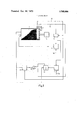
- FIG. 1 represents one embodiment of the invention showing the electric components designed for the simultaneous display of two values
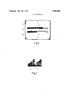
- FIG. 2 is a side view taken through a portion of the means for displaying a value
- FIG. 3 is a plan view of the mask of the display means according to FIG. 2;
- FIG. 4 shows a development of the drum according to FIG. 2;
- FIG. 5 is a side view of a portion of the means for the simultaneous display of two values
- FIG. 6 is a plan view of the mask of the display means according to FIG. 5;
- FIG. 7 shows a group of sector elements on the developed drum in place of the group shown in FIG. 4.
- FIGS. 1, 2, and 3 the drum carrying the preselected display values is only represented schematically.
- the arrangement of the preselected values is shown in more detail in FIG. 4 which represents a development of the drum.
- sector elements 2 are arranged in a step-to-step fashion to achieve a display means of the linear scale type. These sector elements divide the drum surface into contrasting sections. For example, the surface being a photographic film is transparent in section 3 while it is opaque at section 4. Furthermore, a position mark 5 is assigned to each sector element on the drum, said position marks being applied near the edge of the surface. Moreover, the surface carries a synchronisation mark 6.
- a rigid mask 7 with a slot 8 is accommodated in front of the drum of the display means, said slot being slightly smaller in width than the sector element measured in the direction of the circumference of the drum.
- a flash source 9 is provided inside the drum. While in this embodiment the drum surface is located between the flash source and the mask, in another embodiment the mask may be located inside the drum between the flash source and the surface of the drum. 34
- the drum is coupled to a motor 10.
- a sensor 11 is provided near the edge of the drum sensing the position marks and the synchronisation mark, a line 12 being employed to transmit the position pulses originating from the sensor to a counting unit 14.
- Counting unit 14 and sensor 11 may together be considered part of a general transducer means.
- the counting unit 14 is connected to the sensor by another line 13 transmitting the synchronisation pulses.
- the counting unit is connected to the input of a comparator unit 15, said comparator having a second input 16 for the value to be displayed.
- the output of the comparator unit is coupled to the flash source 9 by a trigger not shown.
- the display means described above is designed for displaying only one value at a time employing the mask shown in FIGS. 2 and 3.
- the drum is continuously rotated by motor 10,
- the value to be displayed is fed into the input 16 of the comparator unit 15, preferably in digitally coded form.
- the electric components of the display means trigger the flash source each time the drum reaches a position corresponding to the value to be displayed, i.e., a position in which the sector element appearing at the slot corresponds to the value to be displayed. This is achieved by continuously counting the position pulses generated each time a position mark is sensed after the counting unit 14 has been reset to a defined starting position by a synchronisation pulse generated when a synchronisation mark is sensed. In other words, after each rotation of the drum a sector element is illuminated. At a sufficiently high speed of rotation the flashing frequency is such that the image of the illuminated sector element in the slot is stationary. A useful flashing frequency is 50 cycles per second.
- the display means may be modified to enable the simultaneous display of several values.
- the drum used is the same as that shown in FIGS. 1 through 4. However, the drum is equipped with a mask 17 having two slots 18 and 19 arranged one above the other. The drum section opposite each slot is illuminated by a separate flash source, i.e. apart from the flash source 9, a second flash source 20 is provided. Inside the drum the two flash sources are separated by means of a light-tight screen.
- any sector element on the drum surface' may be illuminated by any of the two flash sources during one complete cycle of the drum so that stationary images of the values to be displayed are produced at the slots 18, 19.
- the electric components described hereinbefore are employed to display the value visible through slot 18 by means of flash source 9.
- the electric components according to FIG. 1 are essentially complemented by a second comparator unit 21, a storage element on buffer 22, a gate circuit 23, and a counting unit 24.
- the element 22 together with gate circuit 23 and unit 24 may collectively be considered a delay time means.
- the second comparator unit 21 has an input to which, in the same way as described for the comparator unit 15, a figure is transmitted from the counting unit 14, said figure indicating the drum position.
- the second input 21a to the comparator unit 21 receives the value to be displayed.
- a signal is fed into the storage 22 where it is held back for a period of time corresponding to at least the time required by a sector element on the drum to travel between slot 18 and slot 19.
- the output signal of the storage 22 keeps the gate circuit in open position so that the position pulses can be transmitted to the counting unit via the line 12.
- the flash source 20 is triggered by a trigger not shown.
- the storage 22 is then reset.
- the line length remainder is displayed through slot 18, while the total amount of differences between maximum space and minimum space, being an indication for the justification range of a line, is displayed through slot 19.
- the drum at its circumference carries all values to be displayed, as particularly shown in FIG. 4. If the values are to be displayed analogously as in a linear scale with high resolution, it becomes apparent that it is necessary to place a multitude of sector elements side by side an to select a sufficiently large drum circumference at a given size of the slot in the mask. However, it is possible to reduce the circumference of the drum and maintain a high resolution by arranging the sector elements in indicia on said drum, and a synchronisation mark; a stationary mark covering said drum and having a first elongated aperture and a second elongated aperture therein through which a selected information indicia on said drum may be observed; a driving mechanism operatively associated with said drum for continuously rotwo adjacent groups, as shown in FIG.
- FIG. 7 makes it possible to halve the circumference of the drum according to FIG. 4.
- An arrangement of the sector elements according to FIG. 7 requires that a flash source and an element controlling it is assigned to each group of sector elements. All values represented by the sector elements arranged as shown in FIG. 4 can than be displayed by illuminating the sector elements of groups 25 and 26 in FlG. 7. For example, to display a sector element of the left half of the group according to FIG. 4, only one sector element of group 25 according to FIG. 7 has to be illuminated continuously. If it is desired to display a sector element extending into the right half of the group shown in FIG.
- Means for displaying line composing information indicia for use in controlling typesetting machines, said means comprising: a rotatable drum having preselected line composing information indicia displayed thereon, a plurality of position marks, one for each information tating said drum so that said information indicia are serially moved past said first mark aperture; a drum illuminating circuit means including a comparator unit for storing a number corresponding to a selected information indicia to be displayed, means for introducing a count into said comparator unit corresponding to a drum position, said count introducing means comprising sensor means for scanning the drum position marks to generate position pulses as the position marks on said drum are rotated past said sensor means, and a counting means for counting said position pulses, said sensor means also scanning said synchronisation mark once during each rotation of said drum to generate a reset pulse to reset said counting means when the syn chronisation mark is scanned; flash lamp means responsive to the count introduced into said comparator unit being equal to the number stored in said comparator unit for il
- the delay time means comprises a storage element for producing an output signal when the count introduced to said second comparator unit is equal to the number stored therein, an and gate for producing signals responsive to said storage element signal and to concurrent pulses from said transducer means, and a second counting unit for triggering said second flash lamp when signals from said and gate correspond in number to a value stored in said second counting unit which value represents the time it takes an information indicia on said drum to move from said aperture to said second aperture in said mask.
Landscapes
- Manufacture Or Reproduction Of Printing Formes (AREA)
- Illuminated Signs And Luminous Advertising (AREA)
- Paper Feeding For Electrophotography (AREA)
Applications Claiming Priority (1)
| Application Number | Priority Date | Filing Date | Title |
|---|---|---|---|
| DE19702008102 DE2008102B2 (de) | 1970-02-21 | 1970-02-21 | Vorrichtung zur anzeige des zeilenrestwertes und der anschlussmoeglichkeit bei der steuerung von setzmaschinen |
Publications (1)
| Publication Number | Publication Date |
|---|---|
| US3765686A true US3765686A (en) | 1973-10-16 |
Family
ID=5762968
Family Applications (1)
| Application Number | Title | Priority Date | Filing Date |
|---|---|---|---|
| US00116868A Expired - Lifetime US3765686A (en) | 1970-02-21 | 1971-02-19 | Line length and justification indicator for typesetting machines |
Country Status (6)
| Country | Link |
|---|---|
| US (1) | US3765686A (Direct) |
| JP (1) | JPS4927121B1 (Direct) |
| CH (1) | CH523779A (Direct) |
| DE (1) | DE2008102B2 (Direct) |
| FR (1) | FR2062498A5 (Direct) |
| GB (1) | GB1334864A (Direct) |
Citations (12)
| Publication number | Priority date | Publication date | Assignee | Title |
|---|---|---|---|---|
| US1183997A (en) * | 1913-07-11 | 1916-05-23 | Siemens Ag | Justification-indicator. |
| US2000029A (en) * | 1929-09-04 | 1935-05-07 | Teletypesetter Corp | Keyboard perforator and counter |
| US2666911A (en) * | 1948-01-12 | 1954-01-19 | Marchant Calculators Inc | Changeable exhibitor |
| GB972060A (en) * | 1961-11-15 | 1964-10-07 | Linotype Gmbh | Indicating device for perforators |
| US3262379A (en) * | 1964-05-11 | 1966-07-26 | Hughes Aircraft Co | Apparatus for high speed photographic printing |
| US3336849A (en) * | 1965-04-19 | 1967-08-22 | Photon Inc | Photographic composing apparatus |
| US3344722A (en) * | 1965-03-29 | 1967-10-03 | Clary Corp | Data recorder |
| US3450014A (en) * | 1965-08-10 | 1969-06-17 | Crosfield Electronics Ltd | Optical scanners |
| US3490838A (en) * | 1966-03-30 | 1970-01-20 | Olympia Werke Ag | Optical symbol display apparatus |
| US3512132A (en) * | 1967-03-14 | 1970-05-12 | Ibm | Composing apparatus with table lookup mode |
| US3537365A (en) * | 1968-02-29 | 1970-11-03 | Fabritek Instr Inc | Photographic printing apparatus |
| US3592310A (en) * | 1966-09-19 | 1971-07-13 | Ibm | Justification data calculator and display device |
-
1970
- 1970-02-21 DE DE19702008102 patent/DE2008102B2/de active Pending
- 1970-07-14 CH CH1067070A patent/CH523779A/de not_active IP Right Cessation
- 1970-08-29 JP JP45075309A patent/JPS4927121B1/ja active Pending
- 1970-09-22 FR FR7034303A patent/FR2062498A5/fr not_active Expired
- 1970-11-27 GB GB5662370A patent/GB1334864A/en not_active Expired
-
1971
- 1971-02-19 US US00116868A patent/US3765686A/en not_active Expired - Lifetime
Patent Citations (12)
| Publication number | Priority date | Publication date | Assignee | Title |
|---|---|---|---|---|
| US1183997A (en) * | 1913-07-11 | 1916-05-23 | Siemens Ag | Justification-indicator. |
| US2000029A (en) * | 1929-09-04 | 1935-05-07 | Teletypesetter Corp | Keyboard perforator and counter |
| US2666911A (en) * | 1948-01-12 | 1954-01-19 | Marchant Calculators Inc | Changeable exhibitor |
| GB972060A (en) * | 1961-11-15 | 1964-10-07 | Linotype Gmbh | Indicating device for perforators |
| US3262379A (en) * | 1964-05-11 | 1966-07-26 | Hughes Aircraft Co | Apparatus for high speed photographic printing |
| US3344722A (en) * | 1965-03-29 | 1967-10-03 | Clary Corp | Data recorder |
| US3336849A (en) * | 1965-04-19 | 1967-08-22 | Photon Inc | Photographic composing apparatus |
| US3450014A (en) * | 1965-08-10 | 1969-06-17 | Crosfield Electronics Ltd | Optical scanners |
| US3490838A (en) * | 1966-03-30 | 1970-01-20 | Olympia Werke Ag | Optical symbol display apparatus |
| US3592310A (en) * | 1966-09-19 | 1971-07-13 | Ibm | Justification data calculator and display device |
| US3512132A (en) * | 1967-03-14 | 1970-05-12 | Ibm | Composing apparatus with table lookup mode |
| US3537365A (en) * | 1968-02-29 | 1970-11-03 | Fabritek Instr Inc | Photographic printing apparatus |
Also Published As
| Publication number | Publication date |
|---|---|
| DE2008102A1 (Direct) | 1971-03-11 |
| GB1334864A (en) | 1973-10-24 |
| DE2008102B2 (de) | 1971-03-11 |
| FR2062498A5 (Direct) | 1971-06-25 |
| CH523779A (de) | 1972-06-15 |
| JPS4927121B1 (Direct) | 1974-07-15 |
Similar Documents
| Publication | Publication Date | Title |
|---|---|---|
| US3098152A (en) | Means for measuring scale motions | |
| US4563747A (en) | Photocomposing apparatus and method | |
| US3122075A (en) | Photocomposing mechanism | |
| US4519701A (en) | Side printing apparatus | |
| US3291015A (en) | Type composing apparatus | |
| US2528640A (en) | Changeable graduated scale | |
| US2846932A (en) | Photographic type composition | |
| US3765686A (en) | Line length and justification indicator for typesetting machines | |
| US2775172A (en) | Photographic type composing apparatus | |
| US3793507A (en) | Integrated parameter display | |
| US3709117A (en) | Information recording method and system | |
| US3330178A (en) | Apparatus for checking the pitch of spaced visible effects in the course of being formed in a travelling strip or web | |
| US3733977A (en) | Photographic type-composing machines | |
| GB918690A (en) | Improvements relating to type composition | |
| US2269240A (en) | Recording instrument | |
| US4097875A (en) | Shaft encoder | |
| USRE25354E (en) | Photocomposing machine | |
| US3810197A (en) | Method and system for inter-character space modification to adjust the length of a line of copy to fit an allotted line length | |
| US3434453A (en) | Indicating device | |
| US3219806A (en) | Typesetting apparatus | |
| US4229086A (en) | Photosensitive recorder providing linguistic characters | |
| US3251055A (en) | Solid state analog to digital display scanner | |
| US3162105A (en) | Type composing apparatus | |
| US3727214A (en) | Synchronized stroboscopic display system and apparatus | |
| US3209901A (en) | Indicator apparatus for line casting machines |
Legal Events
| Date | Code | Title | Description |
|---|---|---|---|
| AS | Assignment |
Owner name: ELTRA CORPORATION, OHIO Free format text: CERTIFIED COPY OF MERGER FILED IN THE OFFICE OF SECRETARY OF STATE OF DELAWARE ON JUNE 6, 1980, SHOWING MERGER AND CHANGE OF NAME OF ASSIGNOR;ASSIGNOR:ATREL CORPORATION;REEL/FRAME:003992/0237 Effective date: 19811020 Owner name: ELTRA CORPORATION, A CORP. OF NY Free format text: CERTIFIED COPY OF MERGER FILED IN THE OFFICE OF SECRETARY OF STATE OF DELAWARE ON JUNE 6, 1980, SHOWING MERGER AND CHANGE OF NAME OF ASSIGNOR;ASSIGNOR:ATREL CORPORATION (INTO);REEL/FRAME:003992/0237 Effective date: 19811020 |
|
| AS | Assignment |
Owner name: ALLIED CORPORATION, NEW JERSEY Free format text: ASSIGNMENT OF ASSIGNORS INTEREST;ASSIGNOR:ELTRA CORPORATION;REEL/FRAME:004026/0293 Effective date: 19820531 Owner name: ALLIED CORPORATION; COLUMBIA RD. AND PARK AVE., MO Free format text: ASSIGNMENT OF ASSIGNORS INTEREST.;ASSIGNOR:ELTRA CORPORATION;REEL/FRAME:004026/0293 Effective date: 19820531 |