US3756542A - Aircraft having an auxiliary lift device - Google Patents
Aircraft having an auxiliary lift device Download PDFInfo
- Publication number
- US3756542A US3756542A US00139550A US3756542DA US3756542A US 3756542 A US3756542 A US 3756542A US 00139550 A US00139550 A US 00139550A US 3756542D A US3756542D A US 3756542DA US 3756542 A US3756542 A US 3756542A
- Authority
- US
- United States
- Prior art keywords
- aircraft
- stream
- wing
- flat
- rectangular
- Prior art date
- Legal status (The legal status is an assumption and is not a legal conclusion. Google has not performed a legal analysis and makes no representation as to the accuracy of the status listed.)
- Expired - Lifetime
Links
- 239000012530 fluid Substances 0.000 claims abstract description 14
- 239000003570 air Substances 0.000 claims description 7
- 239000012080 ambient air Substances 0.000 claims description 5
- 230000009471 action Effects 0.000 claims description 4
- 230000003190 augmentative effect Effects 0.000 claims description 4
- 241000985905 Candidatus Phytoplasma solani Species 0.000 claims description 2
- 230000003416 augmentation Effects 0.000 claims description 2
- 239000007789 gas Substances 0.000 abstract description 10
- 230000000694 effects Effects 0.000 description 3
- 230000003068 static effect Effects 0.000 description 3
- 230000008901 benefit Effects 0.000 description 2
- 230000006872 improvement Effects 0.000 description 2
- 238000005192 partition Methods 0.000 description 2
- 210000003462 vein Anatomy 0.000 description 2
- 101100438971 Caenorhabditis elegans mat-1 gene Proteins 0.000 description 1
- 241000282461 Canis lupus Species 0.000 description 1
- 244000261422 Lysimachia clethroides Species 0.000 description 1
- 230000000295 complement effect Effects 0.000 description 1
- 230000004907 flux Effects 0.000 description 1
- 230000030279 gene silencing Effects 0.000 description 1
- 239000008240 homogeneous mixture Substances 0.000 description 1
- 230000001939 inductive effect Effects 0.000 description 1
- 238000009434 installation Methods 0.000 description 1
- 238000009413 insulation Methods 0.000 description 1
- 230000003993 interaction Effects 0.000 description 1
- 239000002184 metal Substances 0.000 description 1
- 239000011490 mineral wool Substances 0.000 description 1
- 230000009467 reduction Effects 0.000 description 1
- 239000007787 solid Substances 0.000 description 1
- 230000001360 synchronised effect Effects 0.000 description 1
Images


Classifications
-
- F—MECHANICAL ENGINEERING; LIGHTING; HEATING; WEAPONS; BLASTING
- F16—ENGINEERING ELEMENTS AND UNITS; GENERAL MEASURES FOR PRODUCING AND MAINTAINING EFFECTIVE FUNCTIONING OF MACHINES OR INSTALLATIONS; THERMAL INSULATION IN GENERAL
- F16D—COUPLINGS FOR TRANSMITTING ROTATION; CLUTCHES; BRAKES
- F16D65/00—Parts or details
- F16D65/02—Braking members; Mounting thereof
- F16D65/04—Bands, shoes or pads; Pivots or supporting members therefor
-
- B—PERFORMING OPERATIONS; TRANSPORTING
- B64—AIRCRAFT; AVIATION; COSMONAUTICS
- B64C—AEROPLANES; HELICOPTERS
- B64C23/00—Influencing air flow over aircraft surfaces, not otherwise provided for
- B64C23/005—Influencing air flow over aircraft surfaces, not otherwise provided for by other means not covered by groups B64C23/02 - B64C23/08, e.g. by electric charges, magnetic panels, piezoelectric elements, static charges or ultrasounds
-
- F—MECHANICAL ENGINEERING; LIGHTING; HEATING; WEAPONS; BLASTING
- F16—ENGINEERING ELEMENTS AND UNITS; GENERAL MEASURES FOR PRODUCING AND MAINTAINING EFFECTIVE FUNCTIONING OF MACHINES OR INSTALLATIONS; THERMAL INSULATION IN GENERAL
- F16D—COUPLINGS FOR TRANSMITTING ROTATION; CLUTCHES; BRAKES
- F16D69/00—Friction linings; Attachment thereof; Selection of coacting friction substances or surfaces
- F16D69/04—Attachment of linings
- F16D2069/0425—Attachment methods or devices
- F16D2069/0441—Mechanical interlocking, e.g. roughened lining carrier, mating profiles on friction material and lining carrier
Definitions
- An aircraft has at the trailing edge of its wing a liftaugmenter flap towards which there can be directed, in the maximum lift configuration, a fluid stream elongated in the wing span direction and produced by a flat fish-tail jet nozzle disposed below the wing undersurface forwards of and near the lift-augmenter flap, so as to increase the lift by deflection of the elongated fluid stream with a correct flow adhesion of the fluid over the upper surface of the flap.
- the fish-tail nozzle is subdivided into elementary nozzles producing as many elementary streams of motive gases which contribute to jet propulsion; these elementary nozzles are in the form of slots extending parallel to one another, in the wing span direction and/or right-angles thereto.
- the trailingedge ailerons can also be short lengthwise of the flow.
- Fish-tail nozzles can be combined very satisfactorily with a flat fairing open at both ends with a static pump effect.
- the fairing can have flaps for controlling its outlet cross-section.
- a fish-tail nozzle possibly in combination with a flat fairing having control flaps, is disposed below an aircraft wing undersurface and extends along the wing span in front of and near the camber ailerons so that the propelling flux leaving the nozzle (or, where applicable, the fairing) in the form of an elongated fluid vein is directed by the control flaps, when the same are in the maximum lift position, on to the camber ailerons so as to increase lift by deflecting flattened cross-section vein, the fluid flowing in the correct manner over the top surface of the camber ailerons.
- a fish-tail nozzle having a static pump ef fect in combination with a flat fairing is subdivided into a sequence of elementary nozzles producing a laminar stream of hot gases, and the fairing is subdivided into as many separate juxtaposed elementary ducts as there are elementary nozzles, each elementary nozzle being associated with an elementary duct to form an elementary static pump.
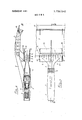
- FIG. 1 is a diagrammatic view in side elevation of an installation according to the invention in the cruising position;
- FIG. 2 is a partial view of the rear portion in the position for auxiliary lift
- FIGS. 3 and 4 are very diagrammatic views of two variants of a complementary constructional detail
- FIG. 5 is a diagramming partial plan view showing a further improvement according to this invention.
- FIG. 6 is a longitudinal section on the line VI-VI of FIG. 5;
- FIG. 7 is a rear elevation in the direction indicated by the arrow VII of FIG. 6;
- FIG. 8 is a view similar to FIG. 6 and shows the control flaps and the camber ailerons in the auxiliary-lift position;
- FIGS. 90, 9b and 9c are views in side elevation, plan and front elevation, respectively, of an aircraft according to this invention.
- FIGS. 10 to 15 are sections similar to the section of FIG. 6 and each showing a constructional variant.
- a turbojet engine I having a bladed thrust reverser 11 is podmounted by means of a streamlined arm 2 below and in front of an aircraft wing 3 having camber ailerons or flaps 10 on its trailing edge.
- the engine 1 intakes air through a front tube 4 which has, with advantage, sound-insulating sleeving and which forms a forwards extension of a pod 5.
- An exhaust pipe 6 for the hot gases has a flat fish-tail shape and terminates in an outlet cross-section 7 comprising a series of cruciform elements 8 through which the hot gases depart as thin lamina at right angles to one another.
- the nozzle 6 has means for deflecting the jet stream upwards towards the ailerons 10 in their auxiliary-lift position, in the manner shown in FIG. 2.
- the cruciform elements 8 are pivoted into the broken-line position in FIG. 3, to which end the elements 8 are mounted by means of a pivot 8a for pivoting around a horizontal axis.
- a deflecting blade 7a visible in FIG. 4 could be used; the blade 7a is disposed at the nozzle outlet 7 and is mounted for pivoting around a horizontal axis.
- the fish-tail nozzle outlet cross-section 7 delivers into a flat fairing 9 which is in shape substantially ob long and which is divided into compartments by soundinsulated longitudinal partitions (not shown) so that each cruciform element 8 is disposed separately in an elementary duct of substantially rectangular crosssection.
- a flat fairing 9 which is in shape substantially ob long and which is divided into compartments by soundinsulated longitudinal partitions (not shown) so that each cruciform element 8 is disposed separately in an elementary duct of substantially rectangular crosssection.
- the ejection system also comprises flaps l313 which are disposed at the fairing trailing edge and which can pivot around transverse pivots 14l4 between two plane end members 15-l5.
- the fairing 9 and its accessories are mounted below the wing 3 on shaped arms l2l2.
- the normal-flight configuration is shown in FIG. 6; the flaps l3- 13 are disposed in extension of the fairing 9 and the ailerons 10 are in the retracted position.
- the configuration shown in FIG. 8 is used, the flaps 13-13 being pointed upwards and the ailerons 10 being brought out.
- the jet stream which leaves the fairing 9 and which is a homogeneous mixture of the inducing hot gases delivered by the engine turbine and the induced ambient air,.is deflected upwards by the flaps l313 and flows over the wing undersurface, and then over the ailerons 10, as indicated by arrows.
- the jet stream from the rectangular ejection device since it has a flattened shape, produces a conlengthwise of the flow.
- the jet stream leaving the fairing 9 is cooler and slower than a conventional jet stream, with a consequent improvement in the mechanical behaviour of the auxiliary-lift system at high speeds and temperature.
- the lift of the other motors can be altered rapidly by operation of the flaps to restore symmetry; clearly, a multi-jet engine aircraft of the kind shown in FIGS. 90, 9b and 9c will have one auxiliary-lift system for each engine.
- the flat fairing 9 is not pod-mounted as in the previous embodiment but placed immediately adjacent and secured to the wing undersurface. Consequently, only a single control flap 13 is provided on that side of the fairing 9 which is remote from the wing. All the air intake into the flat fairing 9 can be from below the wing in cases in which the engine 1 is pod-mounted below the wing, as is shown in FIG. 10; if, however, the jet engine 1 is embedded in the wing, in the manner shown in FIG. 11, the air can be intaken from both sides of the wing 3. In the latter case the nozzle 6 has a goose-neck shape since the axes of the engine 1 and fairing 9 are not in alignment with one another.
- FIG. 12 shows two sets of double flaps 13 disposed in tandem, with synchronised single actuation provided by a reciprocating actuator secured to the fairing mounting arm 12.
- the fairing is sound-insulated and can accordingly be embodied by an outer solid sheetmetal casing 9a (see FIGS. 1315) and a perforate inner sheet-metal casing 9b shaped to bound a convergent-divergent passage, the nozzle outlet plane 7 being disposed at the throat of the latter passage.
- the space between the casings or walls 9a and 9b can be either filled with a sound insulant, such as mineral wool (diagrammatically shown by cross-hatchings) or left empty, in which event the space acts as a resonator, the diameter of the apertures in the wall 9b being determined in dependence upon the predominant frequency of the exhaust gas noise.
- the flaps l3a-l3a which are soundinsulated like the flat fairing 9 which they follow, are rigidly secured to one another and form part of an assembly pivotally connected by a pivot 14a to the fairing support arm 12.
- control flaps l3b-l3c mounted on pivots 14b, 140 can be pivoted towards one another like the shells of the jet stream deflectors known as wolf traps.
- the jet stream leaving the fairing 9 therefore divides into two fractions, one of which is directed upwards by flap 13b to provide the auxiliary lift hereinbefore referred to in cooperation with the ailerons 10, while the other fraction is directed downwardly by the flap 13c and produces a reaction thrust which adds to the aerodynamic lift.
- This feature is particularly suitable for shifting the thrust centre forwards.
- control flaps 13-13 cooperate with retractable deflecting blades 2l--21 which are mounted on pivots 2222 and which can retract into the wing 3.
- An STOL aircraft having at the trailing edge of its wing a lift-augmenter flap system deflectable to lift augmenting position, and a lift-augmenter device designed for producing a fluid stream elongated in the wing span direction and directed to engage said flap system when in said lift augmenting position thereof in order to enhance lift augmentation through aerodynamic action of said fluid stream, said device comprising:
- a flat fish-tail jet nozzle assembly presenting a succession of elementary nozzles spaced substantially parallel to said wing span direction and each in the form of a generally rectangular slot substantially perpendicular to said direction, and
- an open-ended flat ejector shroud having a forwardly facing air intake end and a rearwardly facing stream discharge end which extends below the wing undersurface at a location forward of said flap system, both said ends being of generally recrangular shape with a major side extending substantially parallel to said wing span direction, said flat ejector shroud surrounding said jet nozzle assembly and forming therewith a flat injector wherein ambient air taken in by said rectangular intake end is induced due to the entraining action of the motive gas issuing from said elementary rectangular slotlike nozzles and mixes with said gas to form said elongated fluid stream which issues from said rectangular discharge end.
- said flat fish-tail jet nozzle assembly further comprises a slotlike outlet extending substantially parallel to said wing span direction and intersecting said elementary recrangular slot-like nozzles which extend substantially perpendicular thereto, whereby said jet nozzle assembly is of cruciform pattern.
- said flat ejector shroud is substantially throughout its longitudinal extension of generally rectangular cross-section and comprises an upper wall and a lower wall opposite each other, which first converge towards each other starting from said rectangular air intake end and then diverge from each other towards said rectangular stream discharge end.
- each of said flat fish-tail nozzle assembly and said flat rectangular ejector shroud is pod-mounted in vertically spaced relation below said wing.
- An aircraft as claimed in claim 8 further comprising a passage formed through said wing from the oversurface to the undersurface thereof and leading into said flat rectangular ejector shroud, whereby said flat injector sucks ambient air from said wing oversurface.
- said flat rectangular ejector shroud further comprises a stream deflector vane pivotable about an axis substanpivotable stream deflector vane, when in said feathering position, forms a streamlined rear extension of said lower wall.
- each pivotable stream deflector vane is adjustable to a stream deflecting position in which said stream is fractionated into two parts respectively deflected upwards to engage said liftaugmenter flap system and downwards to produce lifting thrust.
Landscapes
- Engineering & Computer Science (AREA)
- General Engineering & Computer Science (AREA)
- Mechanical Engineering (AREA)
- Aviation & Aerospace Engineering (AREA)
- Structures Of Non-Positive Displacement Pumps (AREA)
- Aerodynamic Tests, Hydrodynamic Tests, Wind Tunnels, And Water Tanks (AREA)
- Testing Of Engines (AREA)
Applications Claiming Priority (1)
| Application Number | Priority Date | Filing Date | Title |
|---|---|---|---|
| FR707016228A FR2087976B1 (enExample) | 1970-05-04 | 1970-05-04 |
Publications (1)
| Publication Number | Publication Date |
|---|---|
| US3756542A true US3756542A (en) | 1973-09-04 |
Family
ID=9055033
Family Applications (1)
| Application Number | Title | Priority Date | Filing Date |
|---|---|---|---|
| US00139550A Expired - Lifetime US3756542A (en) | 1970-05-04 | 1971-05-03 | Aircraft having an auxiliary lift device |
Country Status (5)
| Country | Link |
|---|---|
| US (1) | US3756542A (enExample) |
| CA (1) | CA929919A (enExample) |
| DE (1) | DE2121486A1 (enExample) |
| FR (1) | FR2087976B1 (enExample) |
| GB (1) | GB1336752A (enExample) |
Cited By (15)
| Publication number | Priority date | Publication date | Assignee | Title |
|---|---|---|---|---|
| FR2309727A1 (fr) * | 1975-04-28 | 1976-11-26 | Gen Electric | Dispositif d'ejection manoeuvrable en vol pour moteur a turbine a gaz |
| US4236684A (en) * | 1979-04-27 | 1980-12-02 | The United States Of America As Represented By The Administrator Of The National Aeronautics And Space Administration | Thrust augmented spin recovery device |
| US4358074A (en) * | 1979-05-24 | 1982-11-09 | The Boeing Company | Propulsion system for V/STOL aircraft |
| US4478378A (en) * | 1981-10-15 | 1984-10-23 | Aeritalia-Societa Aerospaziale Italiana-Per Azioni | Aircraft with jet propulsion |
| US4483497A (en) * | 1973-03-16 | 1984-11-20 | Rethorst Scott C | Wide-body supersonic aircraft |
| US5823552A (en) * | 1997-08-25 | 1998-10-20 | Chrysler Corporation | Strut type rear suspension |
| MD1668C2 (ro) * | 1998-11-11 | 2001-12-31 | ЛУКИАНУ Николай | Avion cu decolare şi aterizare scurtă |
| US20050133664A1 (en) * | 2003-12-08 | 2005-06-23 | Cummings Darold B. | Aircraft with thrust vectoring for switchably providing upper surface blowing |
| US20090026283A1 (en) * | 2007-07-26 | 2009-01-29 | Ronald Tatsuji Kawai | Thrust vectoring system and method |
| US20090206207A1 (en) * | 2005-04-18 | 2009-08-20 | Scott Rethorst | Supersonic aircraft footprint spreading control system and method |
| US7823838B1 (en) * | 1980-11-28 | 2010-11-02 | Rolls-Royce Limited | Aircraft with improved lift |
| US20110240804A1 (en) * | 2010-04-01 | 2011-10-06 | Nikolaos Kehayas | Integrated aircraft |
| US20170057648A1 (en) * | 2015-09-02 | 2017-03-02 | Jetoptera, Inc. | Ejector and airfoil configurations |
| US10464668B2 (en) | 2015-09-02 | 2019-11-05 | Jetoptera, Inc. | Configuration for vertical take-off and landing system for aerial vehicles |
| USD868627S1 (en) | 2018-04-27 | 2019-12-03 | Jetoptera, Inc. | Flying car |
Families Citing this family (4)
| Publication number | Priority date | Publication date | Assignee | Title |
|---|---|---|---|---|
| US4645140A (en) * | 1983-08-18 | 1987-02-24 | Rockwell International Corporation | Nozzle system |
| GB2168299A (en) * | 1984-12-13 | 1986-06-18 | Rolls Royce | Aircraft structure with gas turbine engine and thrust reverser |
| GB2249140B (en) * | 1990-08-30 | 1994-12-07 | S & C Thermofluids Ltd | Aircraft engine noise suppression |
| US5216879A (en) * | 1991-08-30 | 1993-06-08 | United Technologies Corporation | Propulsion system assembly |
Citations (8)
| Publication number | Priority date | Publication date | Assignee | Title |
|---|---|---|---|---|
| US2891740A (en) * | 1957-06-27 | 1959-06-23 | John P Campbell | External-flow jet flap |
| US2973922A (en) * | 1959-04-10 | 1961-03-07 | Power Jets Res & Dev Ltd | Jet propelled aircraft |
| US2987136A (en) * | 1955-03-31 | 1961-06-06 | Power Jets Res & Dev Ltd | Apparatus for reducing noise |
| US3133412A (en) * | 1957-08-30 | 1964-05-19 | Westley Robert | Jet noise suppression means and thrust reverser |
| US3154267A (en) * | 1962-03-13 | 1964-10-27 | Charles H Grant | Controlled temperature flow around airfoils |
| US3326500A (en) * | 1964-11-25 | 1967-06-20 | Edward M Lanier | Aircraft lift-increasing device |
| US3532129A (en) * | 1969-02-05 | 1970-10-06 | Rolls Royce | Silencing of gas turbine engines |
| US3579993A (en) * | 1969-08-04 | 1971-05-25 | Rohr Corp | Sound suppression system |
Family Cites Families (1)
| Publication number | Priority date | Publication date | Assignee | Title |
|---|---|---|---|---|
| US3215172A (en) * | 1962-12-24 | 1965-11-02 | Nilsson Robbins & Anderson | Jet engine noise suppressor with shroud for aspiration of air into exhaust stream |
-
1970
- 1970-05-04 FR FR707016228A patent/FR2087976B1/fr not_active Expired
-
1971
- 1971-04-30 DE DE19712121486 patent/DE2121486A1/de active Pending
- 1971-05-03 US US00139550A patent/US3756542A/en not_active Expired - Lifetime
- 1971-05-03 CA CA112025A patent/CA929919A/en not_active Expired
- 1971-05-03 GB GB1275571*[A patent/GB1336752A/en not_active Expired
Patent Citations (8)
| Publication number | Priority date | Publication date | Assignee | Title |
|---|---|---|---|---|
| US2987136A (en) * | 1955-03-31 | 1961-06-06 | Power Jets Res & Dev Ltd | Apparatus for reducing noise |
| US2891740A (en) * | 1957-06-27 | 1959-06-23 | John P Campbell | External-flow jet flap |
| US3133412A (en) * | 1957-08-30 | 1964-05-19 | Westley Robert | Jet noise suppression means and thrust reverser |
| US2973922A (en) * | 1959-04-10 | 1961-03-07 | Power Jets Res & Dev Ltd | Jet propelled aircraft |
| US3154267A (en) * | 1962-03-13 | 1964-10-27 | Charles H Grant | Controlled temperature flow around airfoils |
| US3326500A (en) * | 1964-11-25 | 1967-06-20 | Edward M Lanier | Aircraft lift-increasing device |
| US3532129A (en) * | 1969-02-05 | 1970-10-06 | Rolls Royce | Silencing of gas turbine engines |
| US3579993A (en) * | 1969-08-04 | 1971-05-25 | Rohr Corp | Sound suppression system |
Cited By (34)
| Publication number | Priority date | Publication date | Assignee | Title |
|---|---|---|---|---|
| US4483497A (en) * | 1973-03-16 | 1984-11-20 | Rethorst Scott C | Wide-body supersonic aircraft |
| US4000610A (en) * | 1975-04-28 | 1977-01-04 | General Electric Company | Flight maneuverable nozzle for gas turbine engines |
| FR2309727A1 (fr) * | 1975-04-28 | 1976-11-26 | Gen Electric | Dispositif d'ejection manoeuvrable en vol pour moteur a turbine a gaz |
| US4236684A (en) * | 1979-04-27 | 1980-12-02 | The United States Of America As Represented By The Administrator Of The National Aeronautics And Space Administration | Thrust augmented spin recovery device |
| US4358074A (en) * | 1979-05-24 | 1982-11-09 | The Boeing Company | Propulsion system for V/STOL aircraft |
| US7823838B1 (en) * | 1980-11-28 | 2010-11-02 | Rolls-Royce Limited | Aircraft with improved lift |
| US4478378A (en) * | 1981-10-15 | 1984-10-23 | Aeritalia-Societa Aerospaziale Italiana-Per Azioni | Aircraft with jet propulsion |
| US5823552A (en) * | 1997-08-25 | 1998-10-20 | Chrysler Corporation | Strut type rear suspension |
| MD1668C2 (ro) * | 1998-11-11 | 2001-12-31 | ЛУКИАНУ Николай | Avion cu decolare şi aterizare scurtă |
| US20050133664A1 (en) * | 2003-12-08 | 2005-06-23 | Cummings Darold B. | Aircraft with thrust vectoring for switchably providing upper surface blowing |
| US6926229B2 (en) * | 2003-12-08 | 2005-08-09 | The Boeing Company | Aircraft with thrust vectoring for switchably providing upper surface blowing |
| US20090206207A1 (en) * | 2005-04-18 | 2009-08-20 | Scott Rethorst | Supersonic aircraft footprint spreading control system and method |
| US7861966B2 (en) | 2005-04-18 | 2011-01-04 | Vehicle Research Corporation | Supersonic aircraft footprint spreading control system and method |
| US20090026283A1 (en) * | 2007-07-26 | 2009-01-29 | Ronald Tatsuji Kawai | Thrust vectoring system and method |
| US8240125B2 (en) | 2007-07-26 | 2012-08-14 | The Boeing Company | Thrust vectoring system and method |
| US20110240804A1 (en) * | 2010-04-01 | 2011-10-06 | Nikolaos Kehayas | Integrated aircraft |
| US20170057648A1 (en) * | 2015-09-02 | 2017-03-02 | Jetoptera, Inc. | Ejector and airfoil configurations |
| EP3344536A4 (en) * | 2015-09-02 | 2019-08-21 | Jetoptera, Inc. | FLUIDIC DRIVE SYSTEM |
| KR20180061182A (ko) * | 2015-09-02 | 2018-06-07 | 제톱테라 잉크. | 이젝터 및 에어포일 구조체 |
| CN108137150A (zh) * | 2015-09-02 | 2018-06-08 | 杰托普特拉股份有限公司 | 流体推进系统 |
| CN108137149A (zh) * | 2015-09-02 | 2018-06-08 | 杰托普特拉股份有限公司 | 喷射器和翼型构型 |
| US20180312268A1 (en) * | 2015-09-02 | 2018-11-01 | Jetoptera, Inc. | Ejector and airfoil configurations |
| JP2018532647A (ja) * | 2015-09-02 | 2018-11-08 | ジェトプテラ、インコーポレイテッド | エジェクタ及びエアフォイル形状 |
| US10207812B2 (en) | 2015-09-02 | 2019-02-19 | Jetoptera, Inc. | Fluidic propulsive system and thrust and lift generator for aerial vehicles |
| EP3344535A4 (en) * | 2015-09-02 | 2019-05-15 | Jetoptera, Inc. | EJECTOR AND PAD CONFIGURATIONS |
| WO2017065858A3 (en) * | 2015-09-02 | 2017-07-13 | Jetoptera, Inc. | Ejector and airfoil configurations |
| US10464668B2 (en) | 2015-09-02 | 2019-11-05 | Jetoptera, Inc. | Configuration for vertical take-off and landing system for aerial vehicles |
| AU2024200376B2 (en) * | 2015-09-02 | 2025-07-10 | Jetoptera, Inc. | Fluidic propulsive system |
| US10800538B2 (en) * | 2015-09-02 | 2020-10-13 | Jetoptera, Inc. | Ejector and airfoil configurations |
| CN108137150B (zh) * | 2015-09-02 | 2021-07-06 | 杰托普特拉股份有限公司 | 流体推进系统 |
| CN108137149B (zh) * | 2015-09-02 | 2021-07-06 | 杰托普特拉股份有限公司 | 喷射器和翼型构型 |
| AU2021203495B2 (en) * | 2015-09-02 | 2023-10-19 | Jetoptera, Inc. | Fluidic propulsive system |
| EP4306789A3 (en) * | 2015-09-02 | 2024-06-12 | Jetoptera, Inc. | Fluidic propulsive system |
| USD868627S1 (en) | 2018-04-27 | 2019-12-03 | Jetoptera, Inc. | Flying car |
Also Published As
| Publication number | Publication date |
|---|---|
| FR2087976B1 (enExample) | 1973-03-16 |
| DE2121486A1 (de) | 1971-12-02 |
| GB1336752A (en) | 1973-11-07 |
| FR2087976A1 (enExample) | 1972-01-07 |
| CA929919A (en) | 1973-07-10 |
Similar Documents
| Publication | Publication Date | Title |
|---|---|---|
| US3756542A (en) | Aircraft having an auxiliary lift device | |
| US4505443A (en) | Propulsion system for a V/STOL airplane | |
| US7150432B2 (en) | Horizontal augmented thrust system and method for creating augmented thrust | |
| EP1903205A2 (en) | Thrust reverser nozzle for a turbofan gas turbine engine | |
| IL257810B (en) | Emitter and airfoil configurations | |
| US4709880A (en) | Method and system for improved V/STOL aircraft performance | |
| US9938901B2 (en) | Attachment pylon for a turbine engine | |
| JP2008518828A (ja) | 高揚力の分散型アクティブフローコントロールシステムおよび方法 | |
| US2453721A (en) | Control flap with fluid jets for aircraft | |
| EP3112650B1 (en) | Inlet flow restrictor | |
| US2885162A (en) | Integrated jet-wing | |
| US5934607A (en) | Shock suppression supersonic aircraft | |
| US3223354A (en) | Vertical take off and landing aircraft | |
| US3174707A (en) | Short or vertical take-off and landing aircraft | |
| US2961192A (en) | Jet propelled aircraft | |
| US2675196A (en) | Jet propulsion engine for aircraft | |
| US3613827A (en) | Device for attenuating noise emitted by the jet of a jet engine | |
| US3164337A (en) | Jet aircraft with orientable nozzles for vertical or forward movement | |
| US3724784A (en) | Wing with thrust augmentor | |
| US2945641A (en) | Aircraft with wing containing lifting jets | |
| US3212731A (en) | Fan powered aircraft | |
| US3442471A (en) | Nozzle structure | |
| US2517524A (en) | Boundary layer control | |
| US2940690A (en) | Aircraft with split flaps and gas jet boundary layer control | |
| US3829044A (en) | Engine arrangement for high performance stol aircraft |