US3751908A - Turbine-compressor - Google Patents
Turbine-compressor Download PDFInfo
- Publication number
- US3751908A US3751908A US00155865A US3751908DA US3751908A US 3751908 A US3751908 A US 3751908A US 00155865 A US00155865 A US 00155865A US 3751908D A US3751908D A US 3751908DA US 3751908 A US3751908 A US 3751908A
- Authority
- US
- United States
- Prior art keywords
- turbine
- compressor
- section
- wall
- rotor
- Prior art date
- Legal status (The legal status is an assumption and is not a legal conclusion. Google has not performed a legal analysis and makes no representation as to the accuracy of the status listed.)
- Expired - Lifetime
Links
Images


Classifications
-
- F—MECHANICAL ENGINEERING; LIGHTING; HEATING; WEAPONS; BLASTING
- F01—MACHINES OR ENGINES IN GENERAL; ENGINE PLANTS IN GENERAL; STEAM ENGINES
- F01D—NON-POSITIVE DISPLACEMENT MACHINES OR ENGINES, e.g. STEAM TURBINES
- F01D1/00—Non-positive-displacement machines or engines, e.g. steam turbines
- F01D1/34—Non-positive-displacement machines or engines, e.g. steam turbines characterised by non-bladed rotor, e.g. with drilled holes
- F01D1/36—Non-positive-displacement machines or engines, e.g. steam turbines characterised by non-bladed rotor, e.g. with drilled holes using fluid friction
-
- F—MECHANICAL ENGINEERING; LIGHTING; HEATING; WEAPONS; BLASTING
- F02—COMBUSTION ENGINES; HOT-GAS OR COMBUSTION-PRODUCT ENGINE PLANTS
- F02C—GAS-TURBINE PLANTS; AIR INTAKES FOR JET-PROPULSION PLANTS; CONTROLLING FUEL SUPPLY IN AIR-BREATHING JET-PROPULSION PLANTS
- F02C3/00—Gas-turbine plants characterised by the use of combustion products as the working fluid
- F02C3/04—Gas-turbine plants characterised by the use of combustion products as the working fluid having a turbine driving a compressor
-
- F—MECHANICAL ENGINEERING; LIGHTING; HEATING; WEAPONS; BLASTING
- F04—POSITIVE - DISPLACEMENT MACHINES FOR LIQUIDS; PUMPS FOR LIQUIDS OR ELASTIC FLUIDS
- F04D—NON-POSITIVE-DISPLACEMENT PUMPS
- F04D23/00—Other rotary non-positive-displacement pumps
Definitions
- ABSTRACT A turbine-compressor for feeding a gas to a combustion chamber.
- a rotor having circumferentially grooved passages.
- One portion of the housing inner cylindrical wall contains the inlet and exhaust sections and somewhat opposite the inlet and exhaust section is the combustion section.
- At the one, and at the other of these sections is an inner and outer, somewhat radial wall, having an adjustable orientation.
- These radial walls have teeth which enter the circumferentially grooved passages making a substantially sealed contact with the rotor.
- These walls and teeth form gas flow guides.
- the rotor is rotated at over about 1100 feet per second, forcing the gas into the combustion chamber where burning occurs. The fluid then reenters the casing through a nozzle and expands through the turbine side of the casing.
- the present invention relates to a turbinecompressor combustion engine and more particularly to a combustion engine of simple construction with possible increased efficiency and reduction in airpollution components.
- the compressor section of the said engine is also capable of being driven by an auxiliary engine to act as a simple compressor.
- the turbine can be utilized as a driver to operate another type of compressor.
- the turbine-compressor combustion engine, or the compressor sections, or the turbine sections can be utilized in series or in parallel to form a multiplicity of combinations.
- the present invention contemplates a turbine-compressor for feeding a gas to a combustion chamber.
- a turbine-compressor for feeding a gas to a combustion chamber.
- a rotor having circumferentially grooved passages.
- One portion of the housing inner cylindrical wall contains the inlet and exhaust sections and somewhat opposite the inlet and exhaust section is the combustion section.
- At the one, and at the other of these sections is an inner and outer, somewhat radial wall, having an adjustable orientation.
- These radial walls have teeth which enter the circumferentially grooved passages making a substantially sealed contact with the rotor.
- These walls and teeth form gas flow guides.
- the rotor is rotated at over about 1,100 feet per second, forcing the gas into the combustion chamber where burning occurs.
- the fluid then reenters the casing through a nozzle and expands through the turbine side of the casing.
- the important facet of the invention is that a gas cannot usually exceed the speed of sound in a channel. Consequently, if the channel is moving at a velocity greater than the speed of sound, the channel will compress gas at one end because the gas does not have the capability of flowing backwards faster than the speed of sound in the gas. Because the strength of modern materials makes it possible for tip speeds of rotors to exceed, 2,000. feet per second and the velocity of sound is only 1,100. feet per second in air at normal temperatures, the invention becomes possible. Also, since the speed of sound in a burned, stoichiometric or near stoichiometric temperature, fuel is much greater than 2,000 feet per second, then the flowing gas tends to drag the channel along and this action can be converted into work.
- FIG. 1 is a schematic top view of a compressor arrangement illustrating a fundamental concept of the invention
- FIG. 2 is a perspective view of the interior of the housing of the turbine-compressor contemplated herein, with the floor and ceiling removed and the housing inner cylindrical wall partly broken away so as to better show the components therein;
- FIG. 2a is a theoretical top view in schematic form of the inventive concept shown in FIG. 2;
- FIG. 2b shows a perspective view of a portion of FIG. 2 without the housing
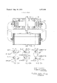
- FIG. 3 presents a cross-sectional view of the inventive concept
- FIG. 4 shows an enlargement of the concept presented in FIG. 3;
- FIG. 5 is another cross-sectional view of a stripper section showing one of the important aspects of the invention.
- FIG. 5a is a view similar to FIG. 5, but using laminations
- FIG. 6 is a cross-sectional view similar to FIG. 4, but showing a seal area with an adjusting mechanism
- FIG. 7 illustrates in perspective one of the components shown in FIG. 5;
- FIG. 8 presents a top view of the apparatus with symbols useful in understanding the mathematical explanation of the inventive concept
- FIG. 9 shows a modification of the inventive concept which is useful in carrying the invention into practice
- FIG. It explains in a cross-sectional view the cascading of the inventive concept to obtain a more useful output.
- FIG. 10a is a schematic explanation of a parallel connection using the inventive. concept
- FIG. 10b is one schematic explanation of a series connection using the inventive concept.
- FIG. 10c shows a second possible series connection in schematic format.
- the turbine-compressor contemplated herein is a gas turbine engine which has both a compression cycle and an expansion cycle occuring on the same wheel. Approximately one half of the circumference of the wheel is used for compression, while approximately the remaining one half is used for expansion.
- the compressor side of the wheel 20 is shown schematically in FIG. 1.
- a gas at atmospheric conditions enters an intake nozzle 22 which channels it into the rotary element 24.
- the wheel has flow passages 26 con sisting of several thin, deep, circumferential grooves which will be described at length herein.
- the wheel which has a high surface speed in the direction of flow literally drags the mixture through the casing 28.
- the mixture movesthrough an arc of about in the casing 28 to the point where a stripper assembly 30 strips the mixture from the wheel.
- the air then moves out of the casing through a port to a combustion chamber 32.
- That portion of the wheel on the second arc, not shown in the drawing, will then form the turbine side of the apparatus.
- the gas necessary to drive the turbine is supplied from a combustion chamber 32.
- the stripper assembly 30 separates the compressor side from the combustion side.
- Another stripper assembly 34 towards the intake side will strip the exhaust gas from the wheel.
- FIG. 2 A more practical apparatus is shown in FIG. 2.
- the turbine-compressor has a housing 280 with an inner cylindrical wall 29 having a defined intakeexhaust section and a combustion section 32a.
- the configuration of these sections will be described in greater detail subsequently herein.
- Rotating along inner cylindrical wall 29 is a diskshaped rotor 20a.
- a diskshaped rotor 20a Around the circumference of the rotor 200 are a plurality of grooved passages 26a which serve to increase the surface area of the rotor. These are shown in FIGS. and 5a as being of rectangular shape, and in FIGS. 4 and 6, grooved passages 26b are shown as being somewhat of truncated triangular shape.
- the rotor 20a is supported for rotation on an axle 36.
- stripper assemblies 30a and 34a are shown in FIGS. 2 and 2b.
- These stn'pper assemblies have two elements, a fixed wall 38, 40 for guiding the inflowing gas and the outflowing exhaust, and partially defines the inlet-exhaust section and the combustion section 32a and a sealing portion 42, 44.
- a fixed wall 38, 40 for guiding the inflowing gas and the outflowing exhaust, and partially defines the inlet-exhaust section and the combustion section 32a and a sealing portion 42, 44.
- teeth 460 At the outer end of the sealing portions 42, 44 are teeth 460 which enter the grooved passages 26a. If the grooved passages are of triangular cross-section, the teeth 46b are likewise triangular in shape.
- the stripper assembly 47 may be laminated and of ceramic or other material. In this case, the sealing portion 420 of the stripper assembly is held together by means of a stripper pin 48.
- the pin 48 may be of such shape as to maintain proper orientation of the assembly.
- the position of the teeth in the grooves is adjustable by a method similar to adjusting mechanism 50.
- the adjustment mechanism 50 has a threaded bolt 52 passing through the housing to engage the stripper assembly and urge it inwards, and a biasing outer spring 54 to hold the threaded bolt 52 in position while the machine is running. If triangular grooves are used and have some wear, this is more effectively compensated for by the insertion of the teeth further in the groove. Other shaped grooves are also possible, such as concave shaped grooves with convex teeth and vice versa.
- the input on the inlet side is through a nozzle shaped passage having an apex into the intake section and then turning substantially tangentially to the rotor to disgourge gas between the rotor passages and the inner cylindrical housing wall.
- On the exhaust side the configuration is somewhat reversed, providing a reverse figure S outlet passage.
- an extended guide wall is not necessary.
- the inflowing gas is sent into a combustion chamber while outgoing exhaust is channeled by a nozzle shaped passage into the exhaust half of the apparatus.
- the high-speed rotor In operation the high-speed rotor literally drags the air from the intake to the exit position where it is stripped from the wheel. After being stripped from the wheel, the air is at a higher pressure than it was at the inlet. The compression is then a function of how much faster the wheel turns relative to the gas flow in the passages.
- the rotor should rotate at circumferential speeds (speed at the tip of the rotor) of between about 1,500 to about 2,300 feet per second. At this speed the velocity of the surfaces is approximately two times that of the velocity of sound in air or other gases at standard conditions.
- the wheel acts as a compressor, i.e., the rotational speed of the wheel is faster than the gas flow.
- the air is mixed with gasoline or similar fuel to form a stoichiometric mixture, the mixture ignited and introduced downstream into the other segment of the wheel, it operates at a pressure sufficiently high to generate a sonic velocity in the passages of the wheel leading to the exhaust exit.
- the gases in this part of the wheel travel at a velocity greater than the wheel speed and the viscous forces that they exert upon the surface tend to drag the wheel around and make it act like a turbine.
- the hot gases are then stripped off the wheel at the other side, or just prior to the entrance of the incoming gas to the compression section of the wheel.
- the high combustion temperature is only intermittently applied to the wheel disk. This is somewhat similar to the stoichiometric temperature which is formed in the cylinder of an internal combustion engine. In a normal internal combustion engine, although the stoichiometric temperature is reached instantaneously, it is not maintained long enough to damage the cylinders of internal working parts of the engine. In the proposed system, the hot gases will continually impinge on the rotating wheel; however, various portions of the rotating wheel will not only be intermittently exposed to the hot gas stream, but will also be intermittently exposed to the cooling influence of the inflowing gas. Consequently, the wheel will never attain stoichiometric temperature.
- a mean wheel temperature approaching l,300 to l.800 F might be attained depending upon the relative lengths of circumference which the turbine and compressor occupy.
- Sonic velocity in air at approximately room temperature is about 1,100 feet per second. Also the sonic velocity in a gasoline air combusted mixture at 3,500 F is about 3,300 feet per second. This makes the combination, if the rotor speed is about 2,000 feet per second, an ideal one for a stoichiometric engine.
- the inlet gas may be a stoichiometric mixture from a carburetor and it passes through the compressor to a combustion chamber where it is ignited.
- the hot combustion gases atabout 3,500 F then flow through the turbine section of the rotor and generate work.
- the rotor is only intermittently exposed to the hot gases and thus the operating temperature of the rotor will remain below a safe value.
- the housing at least of the turbine section may have to be made of ceramic to withstand the high temperatures. After the rotor goes through the turbine section it becomes a part of the compressor and in this position gives up some of the heat it picked up in the turbine section to the incoming air and gasoline. Consequently, the rotor acts like a regenerator for the turbine.
- the apparatus shown and described herein is particularly useful for use in a helicopter.
- two or more units may be cascaded, either in series or in parallel, as shown schematically in FIG. 10.
- the turbine compressor 11a shown in FIG. 10 is similar to the one shown in FIG. 2 and is cascaded with a second turbine compressor 11b. If the intake gas is fed equally through intakes of both 11a and llb and exits into combustion sections. as indicated in H6. 100, the connection is in parallel. It is also possible as indicated in FIG. 10b and FIG. 10c to have the initial intake through one inlet alone with unit 11a acting only as a compressor and have the turbine side be unit llb. In such a case the combustion sections may be arranged either in series as indicated in FIG. 10b or in parallel as indicated in FIG. 10c". Many and varied combinations are possible.
- the output of the turbine-compressor engine can easily be increased by increasing the numbers of the circumferential grooves. Also, by directing the flow to specified numbers of grooves, the power output of the machine may be varied.
- a turbine-compressor comprising in combination:
- a housing having an inner cylindrical wall with an intake-exhaust section and a combustion section defined along portions of said wall,
- a stripper component in each of said sections including teeth-like or comb-like shapes penetrating into said circumferential passages to form a barrier in said sections defining said inlet and exhaust sections and providing gas flow guides from the inlet section to the combustion section along one side of such wall and from the combustion chamber to the exhaust section along the other side of said wall and,
- At least one choke comb along said wall including means permitting said choke comb to swing in and out of the rotor circumferential passages to vary, at will, their cross-sectional areas.
- a turbine-compressor as in claim 1 wherein said rotor has circumferential passages sealed to the housing by labyrinth type grooves cut into the housing and wherein said stripper sections are grooved to form labyrinth seals to prevent gas flow through said stripper sections.
- a turbine-compressor comprising in combination a housing having an inner cylindrical wall with an intake-exhaust section and a combustion section defined along portions of said wall, a rotor having a plurality of circumferential passages thereon disposed for rotation within said cylindrical wall, a stripper component in each of said sections including teeth penetrating into said circumferential passages to form a barrier in said sections defining said inlet and exhaust sections and providing gas flow guides from the inlet section to the combustion section along one side of such wall and from the combustion chamber to the exhaust section least one of said stripper components comprises a laminated assembly of alternate teeth and spacing members provided with registering holes and a pin passes through said holes to hold said teeth and spacing members in assembled position 9.
Landscapes
- Engineering & Computer Science (AREA)
- Mechanical Engineering (AREA)
- General Engineering & Computer Science (AREA)
- Chemical & Material Sciences (AREA)
- Combustion & Propulsion (AREA)
- Structures Of Non-Positive Displacement Pumps (AREA)
Abstract
A turbine-compressor for feeding a gas to a combustion chamber. Within a housing having an inner cylindrical wall, is a rotor having circumferentially grooved passages. One portion of the housing inner cylindrical wall contains the inlet and exhaust sections and somewhat opposite the inlet and exhaust section is the combustion section. At the one, and at the other of these sections is an inner and outer, somewhat radial wall, having an adjustable orientation. These radial walls have teeth which enter the circumferentially grooved passages making a substantially sealed contact with the rotor. These walls and teeth form gas flow guides. The rotor is rotated at over about 1100 feet per second, forcing the gas into the combustion chamber where burning occurs. The fluid then reenters the casing through a nozzle and expands through the turbine side of the casing.
Description
United States Patent [191 Colwell et a].
[ Aug. 14, 1973 l l TURBINE-COMPRESSOR [75] Inventors: Gene T. Colwell, Tucker, Ga;
Thomas W. Jackson, Arlington, Va.
[73] Assignee: Georgia Tech Research Institute,
Atlanta, Ga.
[22] Filed: June 23, 1971 [21] Appl. No.2 155,865
Primary ExaminerCarlton R. Croyle Assistant Examiner-Michael Koczo, Jr. Attorney-Newton, Hopkins & Ormsby [57] ABSTRACT A turbine-compressor for feeding a gas to a combustion chamber. Within a housing having an inner cylindrical wall, is a rotor having circumferentially grooved passages. One portion of the housing inner cylindrical wall contains the inlet and exhaust sections and somewhat opposite the inlet and exhaust section is the combustion section. At the one, and at the other of these sections is an inner and outer, somewhat radial wall, having an adjustable orientation. These radial walls have teeth which enter the circumferentially grooved passages making a substantially sealed contact with the rotor. These walls and teeth form gas flow guides. The rotor is rotated at over about 1100 feet per second, forcing the gas into the combustion chamber where burning occurs. The fluid then reenters the casing through a nozzle and expands through the turbine side of the casing.
10 Claims, 16 Drawing Figures Patented Aug. 14, 1973 5 Sheets-Sheet l GENE T COLWELL THOMAS W. JACKSON INVENTORS m, rang;
4 TURN/3Y5 Patented Aug. 14, 1973 3,751,908
5 Sheets-Sheet 2 GENE T. COLWELL THOMAS W. JACKSON INVENTORS Patented Aug. 14, 1973 5 Sheets-Sheet 3 56 FIG.4
F'IG.6
GENE T COLWELL THOMAS W. JACKSON INVENTORS M 4 ,drrap/vtrs FIG.7
Patented Aug. 14, 1973 3,751,908
5 Sheets-Sheet 4 Fl 6, 9 GENE T. COLWELL THOMAS w. JACKSON INVENTORJ M, MW W lrramtrs Patented Aug. 14, 1973 5 Sheets-Sheet 5,
Ila? F56 LEW EXHAUST INLET EXHAUST Hb EXHAUST EXHAUST FIG IOd FIG lOb FIG IOc GENE T. COLWELL THOMAS W. JACKSON INVENTORS 4rroeA/frs Mm TURBINE-COMPRESSOR BACKGROUND OF THE INVENTION The present invention relates to a turbinecompressor combustion engine and more particularly to a combustion engine of simple construction with possible increased efficiency and reduction in airpollution components. The compressor section of the said engine is also capable of being driven by an auxiliary engine to act as a simple compressor. Also the turbine can be utilized as a driver to operate another type of compressor. The turbine-compressor combustion engine, or the compressor sections, or the turbine sections can be utilized in series or in parallel to form a multiplicity of combinations.
BRIEF SUMMARY OF THE PRIOR ART The use of a turbine to pump fluids, as an input to combustion engines is well known. A patent on such a turbine-pump is the G. Banerian U. S. Pat. No. 2,836,123, and more conventional arrangements appear in the N. Tesla U. S. Pat. Nos. 1,061,142 and No. 1,061,206.
Until recently, fluid flow systems were limited to those where the Mach number (the ratio of the velocity of the fluid to the velocity of sound in the fluid) at any point of the system would allow a predictable performance. If the Mach number became too high, mathematical capabilities to predict the fluid flow velocity and direction, temperature, and other effects where either unavailable or so complex as to deter accurate modeling of a high speed fluid-surface interacting system. With the advent of high speed computers and the introduction of new high strength materials out of which to make turbine and compressor wheels, it be- SUMMARY OF THE INVENTION Generally speaking, the present invention contemplates a turbine-compressor for feeding a gas to a combustion chamber. Within a housing having an inner cylindrical wall, is a rotor having circumferentially grooved passages. One portion of the housing inner cylindrical wall contains the inlet and exhaust sections and somewhat opposite the inlet and exhaust section is the combustion section. At the one, and at the other of these sections is an inner and outer, somewhat radial wall, having an adjustable orientation. These radial walls have teeth which enter the circumferentially grooved passages making a substantially sealed contact with the rotor. These walls and teeth form gas flow guides. The rotor is rotated at over about 1,100 feet per second, forcing the gas into the combustion chamber where burning occurs. The fluid then reenters the casing through a nozzle and expands through the turbine side of the casing.
The important facet of the invention is that a gas cannot usually exceed the speed of sound in a channel. Consequently, if the channel is moving at a velocity greater than the speed of sound, the channel will compress gas at one end because the gas does not have the capability of flowing backwards faster than the speed of sound in the gas. Because the strength of modern materials makes it possible for tip speeds of rotors to exceed, 2,000. feet per second and the velocity of sound is only 1,100. feet per second in air at normal temperatures, the invention becomes possible. Also, since the speed of sound in a burned, stoichiometric or near stoichiometric temperature, fuel is much greater than 2,000 feet per second, then the flowing gas tends to drag the channel along and this action can be converted into work.
The invention, as well as other objects and advantages thereof, will become more apparent from the following detailed description when taken together with the accompanying drawings.
BRIEF DESCRIPTION OF THE DRAWINGS FIG. 1 is a schematic top view of a compressor arrangement illustrating a fundamental concept of the invention;
FIG. 2 is a perspective view of the interior of the housing of the turbine-compressor contemplated herein, with the floor and ceiling removed and the housing inner cylindrical wall partly broken away so as to better show the components therein;
FIG. 2a is a theoretical top view in schematic form of the inventive concept shown in FIG. 2;
FIG. 2b shows a perspective view ofa portion of FIG. 2 without the housing;
FIG. 3 presents a cross-sectional view of the inventive concept;
FIG. 4 shows an enlargement of the concept presented in FIG. 3;
FIG. 5 is another cross-sectional view of a stripper section showing one of the important aspects of the invention;
FIG. 5a is a view similar to FIG. 5, but using laminations;
FIG. 6 is a cross-sectional view similar to FIG. 4, but showing a seal area with an adjusting mechanism;
FIG. 7 illustrates in perspective one of the components shown in FIG. 5;
FIG. 8 presents a top view of the apparatus with symbols useful in understanding the mathematical explanation of the inventive concept;
FIG. 9 shows a modification of the inventive concept which is useful in carrying the invention into practice;
FIG. It) explains in a cross-sectional view the cascading of the inventive concept to obtain a more useful output.
FIG. 10a is a schematic explanation of a parallel connection using the inventive. concept;
FIG. 10b is one schematic explanation of a series connection using the inventive concept; and,
FIG. 10c shows a second possible series connection in schematic format.
The turbine-compressor contemplated herein is a gas turbine engine which has both a compression cycle and an expansion cycle occuring on the same wheel. Approximately one half of the circumference of the wheel is used for compression, while approximately the remaining one half is used for expansion.
The compressor side of the wheel 20 is shown schematically in FIG. 1. A gas at atmospheric conditions enters an intake nozzle 22 which channels it into the rotary element 24. The wheel has flow passages 26 con sisting of several thin, deep, circumferential grooves which will be described at length herein. The wheel which has a high surface speed in the direction of flow literally drags the mixture through the casing 28. The mixture movesthrough an arc of about in the casing 28 to the point where a stripper assembly 30 strips the mixture from the wheel. The air then moves out of the casing through a port to a combustion chamber 32.
That portion of the wheel on the second arc, not shown in the drawing, will then form the turbine side of the apparatus. The gas necessary to drive the turbine is supplied from a combustion chamber 32. The stripper assembly 30 separates the compressor side from the combustion side. Another stripper assembly 34 towards the intake side will strip the exhaust gas from the wheel. A more practical apparatus is shown in FIG. 2.
The turbine-compressor has a housing 280 with an inner cylindrical wall 29 having a defined intakeexhaust section and a combustion section 32a. The configuration of these sections will be described in greater detail subsequently herein.
Rotating along inner cylindrical wall 29 is a diskshaped rotor 20a. Around the circumference of the rotor 200 are a plurality of grooved passages 26a which serve to increase the surface area of the rotor. These are shown in FIGS. and 5a as being of rectangular shape, and in FIGS. 4 and 6, grooved passages 26b are shown as being somewhat of truncated triangular shape. The rotor 20a is supported for rotation on an axle 36. As can be seen in FIGS. 2 and 2b, on opposed sides of the rotor 20a in the device are stripper assemblies 30a and 34a. These stn'pper assemblies have two elements, a fixed wall 38, 40 for guiding the inflowing gas and the outflowing exhaust, and partially defines the inlet-exhaust section and the combustion section 32a and a sealing portion 42, 44. At the outer end of the sealing portions 42, 44 are teeth 460 which enter the grooved passages 26a. If the grooved passages are of triangular cross-section, the teeth 46b are likewise triangular in shape. As shown in FIG. 5a, the stripper assembly 47 may be laminated and of ceramic or other material. In this case, the sealing portion 420 of the stripper assembly is held together by means of a stripper pin 48. The pin 48 may be of such shape as to maintain proper orientation of the assembly. The position of the teeth in the grooves is adjustable by a method similar to adjusting mechanism 50. The adjustment mechanism 50 has a threaded bolt 52 passing through the housing to engage the stripper assembly and urge it inwards, and a biasing outer spring 54 to hold the threaded bolt 52 in position while the machine is running. If triangular grooves are used and have some wear, this is more effectively compensated for by the insertion of the teeth further in the groove. Other shaped grooves are also possible, such as concave shaped grooves with convex teeth and vice versa.
In the apparatus shown in the drawing (FIG. 2), gas flows from the inlet section through an angle of about 150 to the combustion section. This angle is not critical. The products of the combustion section, as exhaust, then go around the other side of the rotor to the exhaust section. The input on the inlet side is through a nozzle shaped passage having an apex into the intake section and then turning substantially tangentially to the rotor to disgourge gas between the rotor passages and the inner cylindrical housing wall. On the exhaust side the configuration is somewhat reversed, providing a reverse figure S outlet passage. On the combustion side, an extended guide wall is not necessary. The inflowing gas is sent into a combustion chamber while outgoing exhaust is channeled by a nozzle shaped passage into the exhaust half of the apparatus. Gas is prevented from going from the compressor side to the turbine side ofthe apparatus by the use of running facc seals 56 in continuous contact with the rotor. These seals may be composed of any low friction material. Instead of rubbing seals. labyrinth seals between the rotor and housing can be used.
OPERATION OF THE APPARATUS In operation the high-speed rotor literally drags the air from the intake to the exit position where it is stripped from the wheel. After being stripped from the wheel, the air is at a higher pressure than it was at the inlet. The compression is then a function of how much faster the wheel turns relative to the gas flow in the passages. Preferably, the rotor should rotate at circumferential speeds (speed at the tip of the rotor) of between about 1,500 to about 2,300 feet per second. At this speed the velocity of the surfaces is approximately two times that of the velocity of sound in air or other gases at standard conditions. Consequently, even if the gas flow reaches sonic speed in the passages, the wheel acts as a compressor, i.e., the rotational speed of the wheel is faster than the gas flow. At the high pressure exit, if the air is mixed with gasoline or similar fuel to form a stoichiometric mixture, the mixture ignited and introduced downstream into the other segment of the wheel, it operates at a pressure sufficiently high to generate a sonic velocity in the passages of the wheel leading to the exhaust exit. The gases in this part of the wheel travel at a velocity greater than the wheel speed and the viscous forces that they exert upon the surface tend to drag the wheel around and make it act like a turbine. The hot gases are then stripped off the wheel at the other side, or just prior to the entrance of the incoming gas to the compression section of the wheel.
One of the interesting facets of the configuration herein contemplated is that the high combustion temperature is only intermittently applied to the wheel disk. This is somewhat similar to the stoichiometric temperature which is formed in the cylinder of an internal combustion engine. In a normal internal combustion engine, although the stoichiometric temperature is reached instantaneously, it is not maintained long enough to damage the cylinders of internal working parts of the engine. In the proposed system, the hot gases will continually impinge on the rotating wheel; however, various portions of the rotating wheel will not only be intermittently exposed to the hot gas stream, but will also be intermittently exposed to the cooling influence of the inflowing gas. Consequently, the wheel will never attain stoichiometric temperature. A mean wheel temperature approaching l,300 to l.800 F might be attained depending upon the relative lengths of circumference which the turbine and compressor occupy. In the configuration herein contemplated, heat flows from the gas to the wheel on the turbine side and from the wheel to the air stream on the compressor side of the system. Because of the rotational speed of the wheel and the small amount of time that any portion of the wheel is on the hot gas stream side, the wheel surface temperature tends to remain fairly constant.
An explanation of the scientific principles involved is shown in FIG. 8, where Uc the peripheral velocity of the wheel Ua the velocity of the inlet gas Ucg the velocity of the exhaust gas 1,100 feet per second the velocity of sound in the air at standard conditions 3,300 =-feet per second the velocity of sound at turbine side inlet conditions P inlet pressure P combustion chamber pressure P exhaust pressure assuming a wheel circumferential velocity Uc of 2,000 feet per second on the inlet to the combustion chamber cycle Uc l,lfps and P P on the combustion chamber to exhaust cycle 3,300 fps Uc and P P An examination of the construction of the apparatus and a study of the parameters for a useful turbine compressor will show that the apparatus is operating under conditions where the usual mathematical flowequations are not appliable, since choke flow occurs. The mathematical equations, graphs and computer programs have preceeded the invention and were presented as a masters degree thesis, Suit Dusadeenoad Characteristics of a Viscous Flow Compressor" Sept. 1970, Georgia lnstutite of Technology.
If the rotor tip speed is above the air flow velocity, then the air will be pumped from P to P, as indicated in the figure. This will always be true if the tendency to have back flow due to the pressure difference is less than that induced by the viscous forces of the rotor turning as indicated. In the turbine side, the reaction is as indicated in FIG. 8. Here the high pressure gas at I; is allowed to flow through the passages in the rotor to the low pressure point P It is evident that if the pressures are sufficiently different and the passage spaces small enough to generate viscous forces greater than those on the compressor side, the turbine rotor will spin in the direction indicated. By adjusting the area of the rotor under the influence of the gas or air flow, it is possible to adjust the power generated in the turbine, or the pressure rise in a compressor. It is also possible, as shown in FIG. 9 to place choke combs 58, 580, which may be moved into the grooved passages 26a to regulate the cross-sectional flow areas and, consequently, control the flow on the compressor and turbine sides of the apparatus. This same effect can also be attained by changing the relative positions of the strippers around the periphery.
Sonic velocity in air at approximately room temperature is about 1,100 feet per second. Also the sonic velocity in a gasoline air combusted mixture at 3,500 F is about 3,300 feet per second. This makes the combination, if the rotor speed is about 2,000 feet per second, an ideal one for a stoichiometric engine. The inlet gas may be a stoichiometric mixture from a carburetor and it passes through the compressor to a combustion chamber where it is ignited. The hot combustion gases atabout 3,500 F, then flow through the turbine section of the rotor and generate work. The rotor is only intermittently exposed to the hot gases and thus the operating temperature of the rotor will remain below a safe value. The housing at least of the turbine section may have to be made of ceramic to withstand the high temperatures. After the rotor goes through the turbine section it becomes a part of the compressor and in this position gives up some of the heat it picked up in the turbine section to the incoming air and gasoline. Consequently, the rotor acts like a regenerator for the turbine.
The apparatus shown and described herein is particularly useful for use in a helicopter. In this application, as well as in similar applications, two or more units may be cascaded, either in series or in parallel, as shown schematically in FIG. 10. The turbine compressor 11a shown in FIG. 10 is similar to the one shown in FIG. 2 and is cascaded with a second turbine compressor 11b. If the intake gas is fed equally through intakes of both 11a and llb and exits into combustion sections. as indicated in H6. 100, the connection is in parallel. It is also possible as indicated in FIG. 10b and FIG. 10c to have the initial intake through one inlet alone with unit 11a acting only as a compressor and have the turbine side be unit llb. In such a case the combustion sections may be arranged either in series as indicated in FIG. 10b or in parallel as indicated in FIG. 10c". Many and varied combinations are possible.
The output of the turbine-compressor engine can easily be increased by increasing the numbers of the circumferential grooves. Also, by directing the flow to specified numbers of grooves, the power output of the machine may be varied.
I claim:
1. A turbine-compressor comprising in combination:
a. a housing having an inner cylindrical wall with an intake-exhaust section and a combustion section defined along portions of said wall,
b. a rotor disposed for rotation within said cylindrical wall with a plurality of circumferential passages thereon,
c. a stripper component in each of said sections including teeth-like or comb-like shapes penetrating into said circumferential passages to form a barrier in said sections defining said inlet and exhaust sections and providing gas flow guides from the inlet section to the combustion section along one side of such wall and from the combustion chamber to the exhaust section along the other side of said wall and,
d. at least one choke comb along said wall including means permitting said choke comb to swing in and out of the rotor circumferential passages to vary, at will, their cross-sectional areas.
2. A turbine compressor as in claim 1 wherein said circumferential passages are of rectangular crosssection.
3. A turbine compressor as in claim 1 wherein said circumferential passages are of truncated triangular cross-section.
4. A turbine-compressor as in claim 1 wherein said rotor has circumferential passages sealed to the housing by labyrinth type grooves cut into the housing and wherein said stripper sections are grooved to form labyrinth seals to prevent gas flow through said stripper sections.
5. A turbine-compressor comprising in combination a housing having an inner cylindrical wall with an intake-exhaust section and a combustion section defined along portions of said wall, a rotor having a plurality of circumferential passages thereon disposed for rotation within said cylindrical wall, a stripper component in each of said sections including teeth penetrating into said circumferential passages to form a barrier in said sections defining said inlet and exhaust sections and providing gas flow guides from the inlet section to the combustion section along one side of such wall and from the combustion chamber to the exhaust section least one of said stripper components comprises a laminated assembly of alternate teeth and spacing members provided with registering holes and a pin passes through said holes to hold said teeth and spacing members in assembled position 9. A turbine compressor as in claim 8 wherein said holes and pin are shaped to maintain proper orientation of said laminated assembly.
10. A turbine compressor as in claim 5 wherein said circumferential grooves and teeth are of truncated triangular cross section.
Claims (10)
1. A turbine-compressor comprising in combination: a. a housing having an inner cylindrical wall with an intakeexhaust section and a combustion section defined along portions of said wall, b. a rotor disposed for rotation within said cylindrical wall with a plurality of circumferential passages thereon, c. a stripper component in each of said sections including teeth-like or comb-like shapes penetrating into said circumferential passages to form a barrier in said sections defining said inlet and exhaust sections and providing gas flow guides from the inlet section to the combustion section along one side of such wall and from the combustion chamber to the exhaust section along the other side of said wall and, d. at least one choke comb along said wall including means permitting said choke comb to swing in and out of the rotor circumferential passages to vary, at will, their crosssectional areas.
2. A turbine compressor as in claim 1 wherein said circumferential passages are of rectangular cross-section.
3. A turbine compressor as in claim 1 wherein said circumferential passages are of truncated triangular cross-section.
4. A turbine-compressor as in claim 1 wherein said rotor has circumferential passages sealed to the housing by labyrinth type grooves cut into the housing and wherein said stripper sections are grooved to form labyrinth seals to prevent gas flow through said stripper sections.
5. A turbine-compressor comprising in combination a housing having an inner cylindrical wall with an intake-exhaust section and a combustion section defined along portions of said wall, a rotor having a plurality of circumferential passages thereon disposed for rotation within said cylindrical wall, a stripper component in each of said sections including teeth penetrating into said circumferential passages to form a barrier in said sections defining said inlet and exhaust sections and providing gas flow guides from the inlet section to the combustion section along one side of such wall and from the combustion chamber to the exhaust section along the other side of said wall, and means for radially adjusting the position of said teeth in said circumferential passages.
6. A turbine-compressor as in claim 5 wherein said adjusting means comprises bolts threadedly passing through a wall of said housing and engaging the stripper components to urge them inwards.
7. A turbine-compressor as in claim 6 wherein each bolt is provided with a biasing outer spring engaging between the housing and the head of the bolt to hold the bolt in position.
8. A turbine-compressor as in claim 5 wherein at least one of said stripper components comprises a laminated assembly of alternate teeth and spacing members provided with registering holes and a pin passes through said holes to hold said teeth and spacing members in assembled position.
9. A turbine compressor as in claim 8 wherein said holes and pin are shaped to maintain proper orientation of said laminated assembly.
10. A turbine compressor as in claim 5 wherein said circumferential grooves and teeth are of truncated triangular cross section.
Applications Claiming Priority (1)
| Application Number | Priority Date | Filing Date | Title |
|---|---|---|---|
| US15586571A | 1971-06-23 | 1971-06-23 |
Publications (1)
| Publication Number | Publication Date |
|---|---|
| US3751908A true US3751908A (en) | 1973-08-14 |
Family
ID=22557085
Family Applications (1)
| Application Number | Title | Priority Date | Filing Date |
|---|---|---|---|
| US00155865A Expired - Lifetime US3751908A (en) | 1971-06-23 | 1971-06-23 | Turbine-compressor |
Country Status (1)
| Country | Link |
|---|---|
| US (1) | US3751908A (en) |
Cited By (11)
| Publication number | Priority date | Publication date | Assignee | Title |
|---|---|---|---|---|
| US4629395A (en) * | 1983-05-25 | 1986-12-16 | National Research Development Corp. | Fluid-powered rotary motor |
| US4732529A (en) * | 1984-02-29 | 1988-03-22 | Shimadzu Corporation | Turbomolecular pump |
| US4732530A (en) * | 1984-07-25 | 1988-03-22 | Hitachi, Ltd. | Turbomolecular pump |
| US5240371A (en) * | 1989-10-16 | 1993-08-31 | Belomestnov Petr I | Multiple disc fan with rotatable casing |
| FR2770258A1 (en) * | 1997-10-23 | 1999-04-30 | Ignacio Sierro | Linear motor with compression reduction |
| US6568900B2 (en) | 1999-02-01 | 2003-05-27 | Fantom Technologies Inc. | Pressure swing contactor for the treatment of a liquid with a gas |
| FR2904367A1 (en) * | 2006-07-27 | 2008-02-01 | Bruno Richard Nicol Fauconnier | Gas turbine for e.g. helicopter, has casing including air inlet for receiving air, and turbo-compressor including upper part that transforms gas coming out from combustion chamber into mechanical energy and evacuating energy in exhaust |
| US20110073412A1 (en) * | 2009-09-28 | 2011-03-31 | Tlt-Babcock, Inc. | Axial fan compact bearing viscous pump |
| US8863530B2 (en) | 2008-10-30 | 2014-10-21 | Power Generation Technologies Development Fund L.P. | Toroidal boundary layer gas turbine |
| US9052116B2 (en) | 2008-10-30 | 2015-06-09 | Power Generation Technologies Development Fund, L.P. | Toroidal heat exchanger |
| US20160208691A1 (en) * | 2015-01-15 | 2016-07-21 | Pavel Villaseca | Turbine engine with boundary layer turbine |
Citations (6)
| Publication number | Priority date | Publication date | Assignee | Title |
|---|---|---|---|---|
| US1061206A (en) * | 1909-10-21 | 1913-05-06 | Nikola Tesla | Turbine. |
| US1069408A (en) * | 1909-12-22 | 1913-08-05 | Wolfgang Gaede | Method and apparatus for producing high vacuums. |
| US2532831A (en) * | 1945-01-27 | 1950-12-05 | Breese Burners Inc | Combustion chamber and turbine arrangement |
| US2836123A (en) * | 1955-02-04 | 1958-05-27 | Aerojet General Co | Turbo-pump |
| US2992615A (en) * | 1956-02-06 | 1961-07-18 | Farmingdale Corp | Pump for viscous liquids |
| US3635578A (en) * | 1970-04-16 | 1972-01-18 | Gen Electric | Viscous pump for unitized bearing lubrication system |
-
1971
- 1971-06-23 US US00155865A patent/US3751908A/en not_active Expired - Lifetime
Patent Citations (6)
| Publication number | Priority date | Publication date | Assignee | Title |
|---|---|---|---|---|
| US1061206A (en) * | 1909-10-21 | 1913-05-06 | Nikola Tesla | Turbine. |
| US1069408A (en) * | 1909-12-22 | 1913-08-05 | Wolfgang Gaede | Method and apparatus for producing high vacuums. |
| US2532831A (en) * | 1945-01-27 | 1950-12-05 | Breese Burners Inc | Combustion chamber and turbine arrangement |
| US2836123A (en) * | 1955-02-04 | 1958-05-27 | Aerojet General Co | Turbo-pump |
| US2992615A (en) * | 1956-02-06 | 1961-07-18 | Farmingdale Corp | Pump for viscous liquids |
| US3635578A (en) * | 1970-04-16 | 1972-01-18 | Gen Electric | Viscous pump for unitized bearing lubrication system |
Cited By (14)
| Publication number | Priority date | Publication date | Assignee | Title |
|---|---|---|---|---|
| US4629395A (en) * | 1983-05-25 | 1986-12-16 | National Research Development Corp. | Fluid-powered rotary motor |
| US4732529A (en) * | 1984-02-29 | 1988-03-22 | Shimadzu Corporation | Turbomolecular pump |
| US4732530A (en) * | 1984-07-25 | 1988-03-22 | Hitachi, Ltd. | Turbomolecular pump |
| US5240371A (en) * | 1989-10-16 | 1993-08-31 | Belomestnov Petr I | Multiple disc fan with rotatable casing |
| FR2770258A1 (en) * | 1997-10-23 | 1999-04-30 | Ignacio Sierro | Linear motor with compression reduction |
| US6568900B2 (en) | 1999-02-01 | 2003-05-27 | Fantom Technologies Inc. | Pressure swing contactor for the treatment of a liquid with a gas |
| FR2904367A1 (en) * | 2006-07-27 | 2008-02-01 | Bruno Richard Nicol Fauconnier | Gas turbine for e.g. helicopter, has casing including air inlet for receiving air, and turbo-compressor including upper part that transforms gas coming out from combustion chamber into mechanical energy and evacuating energy in exhaust |
| WO2008029269A1 (en) * | 2006-07-27 | 2008-03-13 | Bruno Fauconnier | Gas turbine engine |
| US8863530B2 (en) | 2008-10-30 | 2014-10-21 | Power Generation Technologies Development Fund L.P. | Toroidal boundary layer gas turbine |
| US9052116B2 (en) | 2008-10-30 | 2015-06-09 | Power Generation Technologies Development Fund, L.P. | Toroidal heat exchanger |
| US9243805B2 (en) | 2008-10-30 | 2016-01-26 | Power Generation Technologies Development Fund, L.P. | Toroidal combustion chamber |
| US10401032B2 (en) | 2008-10-30 | 2019-09-03 | Power Generation Technologies Development Fund, L.P. | Toroidal combustion chamber |
| US20110073412A1 (en) * | 2009-09-28 | 2011-03-31 | Tlt-Babcock, Inc. | Axial fan compact bearing viscous pump |
| US20160208691A1 (en) * | 2015-01-15 | 2016-07-21 | Pavel Villaseca | Turbine engine with boundary layer turbine |
Similar Documents
| Publication | Publication Date | Title |
|---|---|---|
| US3751908A (en) | Turbine-compressor | |
| US2963307A (en) | Honeycomb seal | |
| US1329559A (en) | Valvular conduit | |
| US9856791B2 (en) | Wave disc engine apparatus | |
| US4856463A (en) | Variable-cycle reciprocating internal combustion engine | |
| US3292364A (en) | Gas turbine with pulsating gas flows | |
| US3297006A (en) | Rotary pumps and engines | |
| US5224850A (en) | Rotary device with vanes composed of vane segments | |
| US3425665A (en) | Gas turbine rotor blade shroud | |
| US3899875A (en) | Gas regeneration tesla-type turbine | |
| JP2003035151A (en) | Variable-shape turbine | |
| US3964447A (en) | Vane-type rotary internal combustion engine | |
| US6526937B1 (en) | Economical eccentric internal combustion engine | |
| US6105359A (en) | Efficiency enhanced turbine engine | |
| US5966927A (en) | Efficiency enhanced turbine engine | |
| CA1040540A (en) | Rotary engines, compressors and vacuum pumps | |
| US5154149A (en) | Rotary motor/pump | |
| GB1234932A (en) | Improvements in or relating to rotary internal combustion engines of positive displacement type | |
| US3323501A (en) | Rotary blade piston engine | |
| EP0046586B1 (en) | Internal combustion engine | |
| US2419689A (en) | Gas turbine | |
| GB2094890A (en) | Rotary positive-displacement fluid-machines | |
| US4516921A (en) | End seals for a rotary machine | |
| US4558669A (en) | Ignition apparatus for a rotary internal combustion engine | |
| US1603969A (en) | Two-stroke-cycle internal-combustion engine |