US3744641A - Air vented filter leaf - Google Patents
Air vented filter leaf Download PDFInfo
- Publication number
- US3744641A US3744641A US00165255A US3744641DA US3744641A US 3744641 A US3744641 A US 3744641A US 00165255 A US00165255 A US 00165255A US 3744641D A US3744641D A US 3744641DA US 3744641 A US3744641 A US 3744641A
- Authority
- US
- United States
- Prior art keywords
- filter
- leaf
- bolt
- leaves
- passageway
- Prior art date
- Legal status (The legal status is an assumption and is not a legal conclusion. Google has not performed a legal analysis and makes no representation as to the accuracy of the status listed.)
- Expired - Lifetime
Links
- 239000007788 liquid Substances 0.000 claims abstract description 15
- 239000000463 material Substances 0.000 abstract description 4
- 230000002093 peripheral effect Effects 0.000 abstract description 4
- 238000010276 construction Methods 0.000 description 4
- 239000012065 filter cake Substances 0.000 description 4
- 239000007789 gas Substances 0.000 description 4
- 230000001954 sterilising effect Effects 0.000 description 3
- 238000004140 cleaning Methods 0.000 description 2
- 239000004744 fabric Substances 0.000 description 2
- 238000001914 filtration Methods 0.000 description 2
- 239000012530 fluid Substances 0.000 description 2
- 238000012986 modification Methods 0.000 description 2
- 230000004048 modification Effects 0.000 description 2
- 238000004659 sterilization and disinfection Methods 0.000 description 2
- 238000013022 venting Methods 0.000 description 2
- 241000894006 Bacteria Species 0.000 description 1
- 230000001815 facial effect Effects 0.000 description 1
- 238000011065 in-situ storage Methods 0.000 description 1
- 238000003754 machining Methods 0.000 description 1
- 238000000034 method Methods 0.000 description 1
- 238000012545 processing Methods 0.000 description 1
- 238000012216 screening Methods 0.000 description 1
- 239000007787 solid Substances 0.000 description 1
- 238000012546 transfer Methods 0.000 description 1
Images

Classifications
-
- B—PERFORMING OPERATIONS; TRANSPORTING
- B01—PHYSICAL OR CHEMICAL PROCESSES OR APPARATUS IN GENERAL
- B01D—SEPARATION
- B01D36/00—Filter circuits or combinations of filters with other separating devices
- B01D36/001—Filters in combination with devices for the removal of gas, air purge systems
-
- B—PERFORMING OPERATIONS; TRANSPORTING
- B01—PHYSICAL OR CHEMICAL PROCESSES OR APPARATUS IN GENERAL
- B01D—SEPARATION
- B01D29/00—Filters with filtering elements stationary during filtration, e.g. pressure or suction filters, not covered by groups B01D24/00 - B01D27/00; Filtering elements therefor
- B01D29/39—Filters with filtering elements stationary during filtration, e.g. pressure or suction filters, not covered by groups B01D24/00 - B01D27/00; Filtering elements therefor with hollow discs side by side on, or around, one or more tubes, e.g. of the leaf type
-
- B—PERFORMING OPERATIONS; TRANSPORTING
- B01—PHYSICAL OR CHEMICAL PROCESSES OR APPARATUS IN GENERAL
- B01D—SEPARATION
- B01D29/00—Filters with filtering elements stationary during filtration, e.g. pressure or suction filters, not covered by groups B01D24/00 - B01D27/00; Filtering elements therefor
- B01D29/62—Regenerating the filter material in the filter
- B01D29/70—Regenerating the filter material in the filter by forces created by movement of the filter element
- B01D29/72—Regenerating the filter material in the filter by forces created by movement of the filter element involving vibrations
Definitions
- a filter leaf having a peripheral channel frame is secured to an overhead support member by a bolt having an air passage therethrough covered at the top by a perforate filter material to permit the escape of air from the channel'frame when the filter chamber is filledwith liquid.
- the present invention relates in general to pressure leaf filters, and it relates more particularly to a novel filter leaf construction which eliminates the entrapment of air or other gases in the leaf.
- Filter leaves generally include an imperforate peripheral channel frame in which a core piece and overlying sheets of a porous filter material are secured. There is, therefore, a space above the perforate filter surfaces in which air is trapped when the filter chamber is filled with liquid.
- a bacteria control solution does not fill the upper part of the frame with the solution.
- An object of the present invention is, therefore, to
- Another object of this invention is to provide a filter construction wherein all of t he components are contacted when the filter chamber is filled with a liquid.
- the bottom cover 14 is movable between open and sealably closed positions by means of a fluid operated cylinder and piston assem- I bly 17 connected between the hinge l5 and a bracket 18 affixed to the tank'll.
- the tank 11 and the top and bottom covers 12 and 14 thus define a press'urizeable filter chamber to which a liquid to be clarified is s up-' plied through an inlet port 19.
- a plurality of filter leaves are mounted in the filter chamber in face-to-face parallel relationship on an outlet manifold 23 which is mounted along a diameter of the tank 11 near the bottom thereof.
- the filter leaves 20 each includes perforate facial surfaces separated by a core member to provide an internal cavity opening intothe manifold 23.
- the manifold 23 extends through the wall of the tank 11 and pro vides an outlet port 24 from which the clarified liquid flows during normal operation of the filter 10.
- the filter leaves 20 are each fixedly connected at the top to a rigid vibrator bar 25 which extends through a suitable 7 seal in the wall of the tank ll and is connected to a fluid operated vibrator 26 suitably mounted on the outer wall of the tank 11.
- a filter of this general type i is more fully described'in U.S. Pat. No. 3,212,643.
- a rigid bar or the like is generally A further object of this invention-is to provide a selfventing filter leaf adapted for use'in a vibratory'cake removal system.-
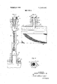
- FIG. 1 is an elevational view of a pressure leaf filter embodying the present invention, part of the tank being "FIG.'2 is an enlarged, cross-sectional view of afilter leaf embodying this invention; v 7
- FIGJ isa cro'ss-sectio nal'view of another vent con- 'struction embodying the present invention.
- each filter leaf 20 includes'a continuous peripheral channel frame member 27 in which is clamped two fine wire or fabric screens-28 and a coarse wire screen or grid 29 which holds the screens 28 apart to provide an internal cavity within the leaf.
- a connector 30 is welded to ;the bottom of the frame 27 atthe centerthereof over an opening 31 and has a broken away to show the filter leaves in the chamber;
- tubular extension 34 slidably and sealably fitted into a sleeve'3 5 extending through the' manifold tube 23 and welded thereto. Accordingly, as liquidis pumped into the filter chamber through theinlet 19 it flows through V the screens 28 into the leaves and thento the manifold 23 through which it exits the filter.
- the top of the frame member 27 is conneeted to the bar 25 by means of an apertured bolt 36 which is threadedly received in a bushing 37welded to the frame 27 over an opening 38 therein.
- the opening 38 is provided at the uppermost part of the frame 27 and in conjunction with the aperture in the bolt 36 provides a vent for releasing air or other gas from the upper portion of the leaf as the filter chamber isfilled.
- the bolt 36 is provided with a narrow axial bore or passageway 39extending through the full length of the bolt and a mum terbore 40 in the head.
- a circularpiece of fine mesh filter material such as wire screening 41 is positioned in, the counterbore 40 over the end of the bore 39 and is held in place by a washer 42.
- the washer 42 and the filter piece 41 are permanently fixed in the head of the bolt 36 as best shown in FIG. 4.
- FIG. 5 there is shown another embodiment of the present invention wherein the air or gas vent is covered by means of a replaceable filter element.
- the basic construction of the filter leaf illustrated in FIG. is the same as that shown in FIG. 2, and therefore, like parts are identified by-the same reference numbers.
- a solid bolt 44 has a threaded shank 45 threadedly received in the bushing 37.
- the shank 45 is provided with a longitudinal surface groove 46 which may be provided by machining a flat thereon.
- a first washer 47 having flat annular surfaces is positioned directly above the bar 25, and a second washer 48 is positioned between the washer 47 and the head of the bolt 44.
- a plurality of radial grooves 49 are provided in the lower face of the washer 47 to provide narrow passageways opening into the annular passageway surrounding the portion of the shank 45 located within the washers 47 and 48.
- the grooves 48 should have a diameter of between 0.001 and 0.010 inch to provide proper filtration of the liquid passing therethrough during the filter cycle.
- the present, invention thus provides a self-venting pressure filter leaf of the bottom drain type which prevents the entrapment of air or other gases in the upper portion of the leaf.
- no moving parts are required.
- the filter cakes which are deposited over the vent apertures are removed during the normal filter cleaning operatiomln the disclosed filter,
- vented filter leaf for clarifying liquids passed therethrough while said leaf is in a vertical position submersed in the liquid to be filtered, comprising an imperforate channel member providing a frame,
- a vented filter leaf according to claim 1 wherein said filter means comprises a threaded member secured to said frame member over said passageway.
- said threaded member comprises a bolt having a bore therethrough, and a fine mesh screen mounted in the head of said bolt across said bore.
- a vented filter leaf according to claim 2 wherein said threaded member comprises 7 a bolt having a longitudinal groove along the shank thereof, and, v v washer means including fine orifices opening onto said groove interposed between said frame member and the head of said bolt.
- said bolt is a mounting bolt for securing saidleaf to an overhead support member.
Landscapes
- Chemical & Material Sciences (AREA)
- Chemical Kinetics & Catalysis (AREA)
- Filtration Of Liquid (AREA)
Abstract
A filter leaf having a peripheral channel frame is secured to an overhead support member by a bolt having an air passage therethrough covered at the top by a perforate filter material to permit the escape of air from the channel frame when the filter chamber is filled with liquid.
Description
I United States Patent 1 i Schmidt, Jr.
[1 1 3,744,641 l [451' July 10,1973
[ AIR VENTED FILTER LEAF [75] Inventor: Henry Schmidt, Jr., Hinsdale, Ill.
- [73] Assignee: Industrial Filter & Pump Mfg. Co.,
Cicero, Ill.
[22] Filed: July 22, I971 21 Appl. No; 165,255
[52] U,S. Cl "210/486 [5]] Int. Cl B0ld 39/00 [58]- Field of Search 2l0/332, 333, 346, 210/388, 486, H38, 120, 436, 445, 446, 472;
[56] 7 References Cited 1 UNITED STATES PATENTS 2,504,683 1/1950 Hainley .L ..210/445 l/l967 Mitchell 210/472 3,212,643 l0/l965 Schmidt et al. 210/332 3,214,368 l0/l965 Muller ..2l0/l88 Primary Examiner CharlesN. Hart Atlurnav-Ruymond E. Fidler, Edmond T. Pulnuude et ul.
| 57 1 ABSTRACT A filter leaf having a peripheral channel frame is secured to an overhead support member by a bolt having an air passage therethrough covered at the top by a perforate filter material to permit the escape of air from the channel'frame when the filter chamber is filledwith liquid.
7 Claims, 5 Drawing Figures PAIENIEU m 1 0191s INVENTOR' ENRY SCHMIDT JR.
A TTORNE Y5 PATENIEU JUL 1 01915 smanrz ATTORNEYS leaf; andthefilter memberis a metallic. screen.
AIR VENTED FILTER LEAF The present invention relates in general to pressure leaf filters, and it relates more particularly to a novel filter leaf construction which eliminates the entrapment of air or other gases in the leaf.
, Filter leaves generally include an imperforate peripheral channel frame in which a core piece and overlying sheets of a porous filter material are secured. There is, therefore, a space above the perforate filter surfaces in which air is trapped when the filter chamber is filled with liquid. When such leaves are used in a food processing system it is difficult to sterilize the inner surfaces of the upper portion of the channel frame-in situ, i.e., filling of the filter chamber with a bacteria control solution does not fill the upper part of the frame with the solution. Hence, other time-consuming cleaning and sterilizing methods must be resorted to where complete sterilization is required.
Aside from the sterilization problems associated with such filter leaves, it sometimes happens that when such leaves are covered with fabric bags, the bags balloon out during the fill operation because the wet bags do notreadily transfer the air from inside the leaves to the filter chamber at the small differential pressuresi'nvolved. At best, increased 'filling'time is required, but in some cases improper precoating and leaf damage can result.
An object of the present invention is, therefore, to
. provide a new andimproved filter leaf construction which is self-venting. I
Another object of this invention is to providea filter construction wherein all of t he components are contacted when the filter chamber is filled with a liquid.
and a plurality of clamps l6, and the bottom cover 14 is movable between open and sealably closed positions by means of a fluid operated cylinder and piston assem- I bly 17 connected between the hinge l5 and a bracket 18 affixed to the tank'll. The tank 11 and the top and bottom covers 12 and 14 thus define a press'urizeable filter chamber to which a liquid to be clarified is s up-' plied through an inlet port 19.
As shown, a plurality of filter leaves are mounted in the filter chamber in face-to-face parallel relationship on an outlet manifold 23 which is mounted along a diameter of the tank 11 near the bottom thereof. As
more fully described hereinafter in connection with FIG. 2, the filter leaves 20 each includes perforate facial surfaces separated by a core member to provide an internal cavity opening intothe manifold 23. The manifold 23 extends through the wall of the tank 11 and pro vides an outlet port 24 from which the clarified liquid flows during normal operation of the filter 10. In the embodimentof the invention illustrated in FIG. I, the filter leaves 20 are each fixedly connected at the top to a rigid vibrator bar 25 which extends through a suitable 7 seal in the wall of the tank ll and is connected to a fluid operated vibrator 26 suitably mounted on the outer wall of the tank 11. A filter of this general type i is more fully described'in U.S. Pat. No. 3,212,643. In those filters not employing a vibratory filter cake re *moval system, a rigid bar or the like is generally A further object of this invention-is to provide a selfventing filter leaf adapted for use'in a vibratory'cake removal system.-
I vided by means of a passageway in a threaded member secured to the uppermost portion of the leaf with the said passageway communicating with the interior of the Further objects'and advantages and a better understandingof theinventionmay be had from the following detailed description takenin connection with the accompanying drawings, wherein: 7
FIG. 1 is an elevational view of a pressure leaf filter embodying the present invention, part of the tank being "FIG.'2 is an enlarged, cross-sectional view of afilter leaf embodying this invention; v 7
FIG. Bisa sectional view of a novel vent constructiontaken along the line 3--3 of FIG. 2; p FIG. MS a top end view of a vented boltassembly embodying the present invention; and
i FIGJ isa cro'ss-sectio nal'view of another vent con- 'struction embodying the present invention.
I v Briefly, theabove and further objects. may be realized I in accordance with the present invention by providing a vent at the top ofthe leaf, which vent is covered by 'a perforate filter member. Preferably, the vent is promounted in the tank and connected to the filter leaves ter chamber. As this description proceeds, itwill be apparent to those skilled in the art that the presentinventionis applicable to these othertypes of'filters. Referring to FIG. 2, each filter leaf 20 includes'a continuous peripheral channel frame member 27 in which is clamped two fine wire or fabric screens-28 and a coarse wire screen or grid 29 which holds the screens 28 apart to provide an internal cavity within the leaf. A connector 30 is welded to ;the bottom of the frame 27 atthe centerthereof over an opening 31 and has a broken away to show the filter leaves in the chamber;
.tubular extension 34 slidably and sealably fitted into a sleeve'3 5 extending through the' manifold tube 23 and welded thereto. Accordingly, as liquidis pumped into the filter chamber through theinlet 19 it flows through V the screens 28 into the leaves and thento the manifold 23 through which it exits the filter. 3
In accordance with the present invention,the top of the frame member 27 is conneeted to the bar 25 by means of an apertured bolt 36 which is threadedly received in a bushing 37welded to the frame 27 over an opening 38 therein.
The opening 38 is provided at the uppermost part of the frame 27 and in conjunction with the aperture in the bolt 36 provides a vent for releasing air or other gas from the upper portion of the leaf as the filter chamber isfilled.
As best shown in FIGS.3 and 4, the bolt 36 is provided with a narrow axial bore or passageway 39extending through the full length of the bolt and a mum terbore 40 in the head. A circularpiece of fine mesh filter material such as wire screening 41 is positioned in, the counterbore 40 over the end of the bore 39 and is held in place by a washer 42. By means of ;a peening or staking operation, the washer 42 and the filter piece 41 are permanently fixed in the head of the bolt 36 as best shown in FIG. 4.
Referring to FIG. 5, there is shown another embodiment of the present invention wherein the air or gas vent is covered by means of a replaceable filter element. The basic construction of the filter leaf illustrated in FIG. is the same as that shown in FIG. 2, and therefore, like parts are identified by-the same reference numbers. A solid bolt 44 has a threaded shank 45 threadedly received in the bushing 37. The shank 45 is provided with a longitudinal surface groove 46 which may be provided by machining a flat thereon. A first washer 47 having flat annular surfaces is positioned directly above the bar 25, and a second washer 48 is positioned between the washer 47 and the head of the bolt 44. A plurality of radial grooves 49 are provided in the lower face of the washer 47 to provide narrow passageways opening into the annular passageway surrounding the portion of the shank 45 located within the washers 47 and 48. The grooves 48 should have a diameter of between 0.001 and 0.010 inch to provide proper filtration of the liquid passing therethrough during the filter cycle.
The present, invention thus provides a self-venting pressure filter leaf of the bottom drain type which prevents the entrapment of air or other gases in the upper portion of the leaf. in the preferred embodiments of the invention illustrated in the drawing, no moving parts are required. Moreover, the filter cakes which are deposited over the vent apertures are removed during the normal filter cleaning operatiomln the disclosed filter,
operation of the vibrator 26 shakes the bar 25 and filter leaves as a unit to dislodgethe filter cakes from the principal filtering surfaces of the leaves and from the vent openings. In sluicing type filters, sluicing jets should be directed toward the vents to remove the filter cakes deposited thereover. ln reverse flow cake removal systems, no changes in the systems are required.
While the present invention has been described in connection with particular embodiments thereof, it will be understood that those skilled in the art may make many changes and modifications without departing from the true spirit and scope thereof. Accordingly, the appended claims are intended to cover all such changes and modifications as fall within the true spirit and scope of the present invention.
I claim:
l. -A vented filter leaf for clarifying liquids passed therethrough while said leaf is in a vertical position submersed in the liquid to be filtered, comprising an imperforate channel member providing a frame,
a plurality of perforate members mounted in spaced apart relationship across said frame,
a clarified liquid outlet passageway extending through said channel member and opening within said leaf between said perforate members,
an open vent passageway disposed in said channel member on the side opposite said outlet passageway, and
a perforate filter means disposed across said vent passageway,
whereby air is not entrapped in the upper portion of said leaf when said leaf is mounted in a filter chamber with said outlet passageway at the bottom and said chamber is filled with liquid.
2. A vented filter leaf according to claim 1 wherein said filter means comprises a threaded member secured to said frame member over said passageway. 3. A vented filter leaf according to claim 2 wherein said threaded member comprises a bolt having a bore therethrough, and a fine mesh screen mounted in the head of said bolt across said bore.
4. A vented filter leaf according to claim 2 wherein said threaded member comprises 7 a bolt having a longitudinal groove along the shank thereof, and, v v washer means including fine orifices opening onto said groove interposed between said frame member and the head of said bolt. 5. A vented filter leaf according to claim-3 wherein said bolt is a mounting bolt for securing saidleaf to an overhead support member. I
6. A plurality of filter leaves according to claim 5 in combination with a rigid bar extending across the tops of said leaves,
and 7 said bolts extending through apertures in said bar with the heads of said bolts disposed above said bar.
7. The invention according to claim 6 comprising a vibrator connected to said bar for vibrating said leaves.
Claims (7)
1. A vented filter leaf for clarifying liquids passed therethrough while said leaf is in a vertical position submersed in the liquid to be filtered, comprising an imperforate channel member providing a frame, a plurality of perforate members mounted in spaced apart relationship across said frame, a clarified liquid outlet passageway extending through said channel member and opening within said leaf between said perforate members, an open vent passageway disposed in said channel member on the side opposite said outlet passageway, and a perforate filter means disposed across said vent passageway, whereby air is not entrapped in the upper portion of said leaf when said leaf is mounted in a filter chamber with said outlet passageway at the bottom and said chamber is filled with liquid.
2. A vented filter leaf according to claim 1 wherein said filter means comprises a threaded member secured to said frame member over said passageway.
3. A vented filter leaf according to claim 2 wherein said threaded member comprises a bolt having a bore therethrough, and a fine mesh screen mounted in the head of said bolt across said bore.
4. A vented filter leaf according to claim 2 wherein said threaded member comprises a bolt having a longitudinal groove along the shank thereof, and washer means including fine orifices opening onto said groove interposed between said frame member and the head of said bolt.
5. A vented filter leaf according to claim 3 wherein said bolt is a mounting bolt for securing said leaf to an overhead support member.
6. A plurality of filter leaves according to claim 5 in combination with a rigid bar extending across the tops of said leaves, and said bolts extending through apertures in said bar with the heads of said bolts disposed above said bar.
7. The invention according to claim 6 comprising a vibrator connected to said bar for vibrating said leaves.
Applications Claiming Priority (1)
| Application Number | Priority Date | Filing Date | Title |
|---|---|---|---|
| US16525571A | 1971-07-22 | 1971-07-22 |
Publications (1)
| Publication Number | Publication Date |
|---|---|
| US3744641A true US3744641A (en) | 1973-07-10 |
Family
ID=22598121
Family Applications (1)
| Application Number | Title | Priority Date | Filing Date |
|---|---|---|---|
| US00165255A Expired - Lifetime US3744641A (en) | 1971-07-22 | 1971-07-22 | Air vented filter leaf |
Country Status (1)
| Country | Link |
|---|---|
| US (1) | US3744641A (en) |
Cited By (4)
| Publication number | Priority date | Publication date | Assignee | Title |
|---|---|---|---|---|
| US5035799A (en) * | 1989-08-21 | 1991-07-30 | Clear Flow, Inc. | Filter assembly |
| US20030010709A1 (en) * | 1999-09-14 | 2003-01-16 | Olli Hognabba | Corrosion-resistant filter element |
| IT201700076718A1 (en) * | 2017-07-07 | 2019-01-07 | Ufi Filters Spa | FILTERING CARTRIDGE WITH VENTILATION DEVICE |
| US20230166203A1 (en) * | 2020-04-28 | 2023-06-01 | Amogreentech Co., Ltd. | Filter module for gravity-type water-purifying device and comprising the same |
-
1971
- 1971-07-22 US US00165255A patent/US3744641A/en not_active Expired - Lifetime
Cited By (8)
| Publication number | Priority date | Publication date | Assignee | Title |
|---|---|---|---|---|
| US5035799A (en) * | 1989-08-21 | 1991-07-30 | Clear Flow, Inc. | Filter assembly |
| US20030010709A1 (en) * | 1999-09-14 | 2003-01-16 | Olli Hognabba | Corrosion-resistant filter element |
| US6843379B2 (en) * | 1999-09-14 | 2005-01-18 | Outokumpu Oyj | Corrosion-resistant filter element |
| IT201700076718A1 (en) * | 2017-07-07 | 2019-01-07 | Ufi Filters Spa | FILTERING CARTRIDGE WITH VENTILATION DEVICE |
| WO2019008536A1 (en) * | 2017-07-07 | 2019-01-10 | Ufi Filters S.P.A. | Filter cartridge with ventilation device |
| US11224832B2 (en) | 2017-07-07 | 2022-01-18 | Ufi Filters S.P.A. | Filter cartridge with ventilation device |
| US20230166203A1 (en) * | 2020-04-28 | 2023-06-01 | Amogreentech Co., Ltd. | Filter module for gravity-type water-purifying device and comprising the same |
| US12311292B2 (en) * | 2020-04-28 | 2025-05-27 | Amogreentech Co., Ltd. | Manifold assemblies for filters |
Similar Documents
| Publication | Publication Date | Title |
|---|---|---|
| US5207930A (en) | Filtration system with helical filter cartridge | |
| US3695443A (en) | Filter apparatus | |
| US4769052A (en) | Compact filter assembly | |
| US3212643A (en) | Filtering apparatus | |
| US4271019A (en) | Filter unit for use in liquid purification apparatus | |
| JPS63185618A (en) | Device for separating solid of fine particle from pressed fluid | |
| US2352269A (en) | Strainer and filter | |
| US3195729A (en) | Unitary rotatable pressure leaf filter | |
| KR910002489A (en) | Continuous filter press | |
| US3211292A (en) | Strainer with concentric filter elements | |
| US3229817A (en) | Assembly for separating immiscible fluids | |
| US2562730A (en) | Filter tube | |
| HU213772B (en) | Backwash filter for filtration of viscous liquids | |
| US3285420A (en) | Filtering equipment | |
| US3421630A (en) | Filter element and filter system | |
| US3288290A (en) | Filter device | |
| US3744641A (en) | Air vented filter leaf | |
| US3708072A (en) | Method and apparatus for controlling filter cake thickness and for compressing a filter cake | |
| JPH0323294Y2 (en) | ||
| US3368679A (en) | Filter with drop-in element | |
| US2744632A (en) | Filtering screen assembly | |
| US3288291A (en) | Bayonet filter device | |
| US3666101A (en) | Multiple filter device | |
| DE944065C (en) | Filter device with ring-shaped filter discs lined up on a central tube | |
| US3542205A (en) | Filter leaf |