US3742417A - Thermal tripping devices for safety installations and the like - Google Patents
Thermal tripping devices for safety installations and the like Download PDFInfo
- Publication number
- US3742417A US3742417A US00207299A US3742417DA US3742417A US 3742417 A US3742417 A US 3742417A US 00207299 A US00207299 A US 00207299A US 3742417D A US3742417D A US 3742417DA US 3742417 A US3742417 A US 3742417A
- Authority
- US
- United States
- Prior art keywords
- arms
- parts
- hook
- relative position
- movable member
- Prior art date
- Legal status (The legal status is an assumption and is not a legal conclusion. Google has not performed a legal analysis and makes no representation as to the accuracy of the status listed.)
- Expired - Lifetime
Links
- 238000009434 installation Methods 0.000 title abstract description 7
- 230000000717 retained effect Effects 0.000 claims description 6
- 210000001331 nose Anatomy 0.000 description 13
- 230000006978 adaptation Effects 0.000 description 2
- 230000006378 damage Effects 0.000 description 2
- 230000014759 maintenance of location Effects 0.000 description 2
- 230000007246 mechanism Effects 0.000 description 2
- 238000009423 ventilation Methods 0.000 description 2
- 230000006835 compression Effects 0.000 description 1
- 238000007906 compression Methods 0.000 description 1
- 238000010276 construction Methods 0.000 description 1
- 230000008034 disappearance Effects 0.000 description 1
- 238000006073 displacement reaction Methods 0.000 description 1
- 230000000694 effects Effects 0.000 description 1
- 238000007493 shaping process Methods 0.000 description 1
- 238000010008 shearing Methods 0.000 description 1
Images
Classifications
-
- F—MECHANICAL ENGINEERING; LIGHTING; HEATING; WEAPONS; BLASTING
- F16—ENGINEERING ELEMENTS AND UNITS; GENERAL MEASURES FOR PRODUCING AND MAINTAINING EFFECTIVE FUNCTIONING OF MACHINES OR INSTALLATIONS; THERMAL INSULATION IN GENERAL
- F16G—BELTS, CABLES, OR ROPES, PREDOMINANTLY USED FOR DRIVING PURPOSES; CHAINS; FITTINGS PREDOMINANTLY USED THEREFOR
- F16G15/00—Chain couplings, Shackles; Chain joints; Chain links; Chain bushes
- F16G15/04—Quickly-detachable chain couplings; Shackles chain links with rapid junction means are classified according to the corresponding kind of chain
-
- A—HUMAN NECESSITIES
- A62—LIFE-SAVING; FIRE-FIGHTING
- A62C—FIRE-FIGHTING
- A62C37/00—Control of fire-fighting equipment
- A62C37/08—Control of fire-fighting equipment comprising an outlet device containing a sensor, or itself being the sensor, i.e. self-contained sprinklers
- A62C37/10—Releasing means, e.g. electrically released
- A62C37/11—Releasing means, e.g. electrically released heat-sensitive
- A62C37/12—Releasing means, e.g. electrically released heat-sensitive with fusible links
Definitions
- ABSTRACT A thermal tripping device for tire protection installations in which an alarm, valve or other appliance is operated by release of a spring biased rod having at one end an eye normally held between two oppositely facing and overlapping hooked or nose shaped parts each formed on an end of two superimposed plate-like arms mounted at their other ends on a common pivot.
- Each arm has a concave part facing the other to define a free space which contains a bulb which explodes above a predetermined temperature to allow the arms to pivot open and release the rod, but while in an intact state the bulb holds the arms locked together.
- This invention relates to improvements in thermal tripping devices of the kind used in safety installations, particularly for fire protection, wherein operation of the devices actuates appliances in the installations, for example, alarms, sprinkler valves or cocks, fireproof curtains or boards, ventilation shutters or traps, safety doors and the like.
- thermo-sensitive element constituted by an explodable bulb, a bimetallic strip or fusible wire arranged to be destroyed, deformed or divided, when the ambient temperature exceeds a certain limit.
- the element is usually disposed to form an abutment for a sliding rod biased by a spring, the free end of the rod being formed to retain a member arranged to operate the appliance, for example, an alarm or so forth. It will be understood that when the ambient temperature rises above the pre-determined threshold, the thermo-sensitive element releases the sliding rod, which is displaced under the spring action thus operating the corresponding appliance.
- An object of the invention is to obviate or reduce the above-mentioned drawback and provide a construction of thermal tripping device capable of efficient and reliable operation whatever force is exerted for actuating the apparatus connected to thedevice.
- a thermal tripping device for actuating an apparatus of a safety installation and the like comprises at least one pivoted arm which has a shaped part for co-operating with the moving member for actuating the corresponding apparatus, and said arm being angularly retained by a thermo-sensitive element against the pivoting force which is applied to the arm by the said member.
- thermo-sensitive element in such a mechanism, two variable factors enable the adaptation of the mechanical resistance of the thermo-sensitive element to the actuating or retaining force exerted by the moving member of the appliance.
- One variable is the inclination given to the shaped part of the arm with respect to the axis along which the force is exerted and the other variable is the location of the thermo-sensitive element with respect to the pivot point of the arm, which works like a lever.
- the device comprises two pivoted arms which, at one end of the device, define two retaining parts or noses adapted to be introduced inside a loop or an eyelet provided at an end of the moving member for actuating the corresponding appliance, inner overlapping edges the said retaining parts being obliquely directed so that traction exerted by the loop parallel to the axis of the arms tends to make the arms pivot open.
- the thermosensitive element is advantageously constituted by an explodable bulb housed in a free space provided between two stamped parts disposed opposite to one another in the arms at a location between a pivot pin for the arms and the retaining parts, in such a manner that once mounted in position, the intact bulb opposes the angular displacement of the arms.
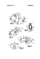
- FIG. 1 is an exploded view showing various elements which form a thermal tripping device formed according to the invention
- FIG. 2 is a perspective view of the device assembled from the components in FIG. 1;
- FIG. 3 is a diagrammatic cross sectional view on line III-III in FIG. 2;
- FIG. 4 is a side view illustrating the operation of the device
- FIG. 5 is a fragmentary side view, on a larger scale, showing the arrangement of the retaining noses.
- the tripping device shown comprises two identical arms 1 formed by the same cutting and shaping tool.
- Each arm 1 has at one of its ends an aperture 2 for the engagement of a common pivot pin 3.
- each of the arms is cut so as to determine a retaining hook-shaped part or nose 4 having an inner edge 4a obliquely directed towards the terminal edge of the nose, the two edges 4a overlapping each other.
- each nose 4 is laterally offset with respect to the longitudinal axis of the corresponding arm 1, so that once the arms 1 are engaged on the pivot pin 3, the two noses 4 cross and overlap each other in the manner shown in FIG. 2, thus ensuring the retention of the arms along the pin 3.
- each arm 1 comprises a stamped part 5 in the form of an outwardly shaped relief apertured at 5a.
- the stamped parts 5 define an inner housing into which is introduced (see FIGS. 1 and 3) an explodable bulb 6 of any suitable known type used in safety installations.
- the pin 3 is shown supported by a fixed support 7 in the shape of a fork, whereas the noses 4 cooperate with a loop 8a provided at the end of a moving member 8 for actuating an appliance, for example an alarm, valve or so forth, connected to the device.
- the member 8 is biased elastically in the direction of arrow F, i.e., along the longitudinal axis of the arms I. Because of the inclination of the shaped edges 4a, the biasing force acts to open the arms 1, but the latter are, angularly retained by the extra thickness provided between the arms by the bulb 6. The arms so locked remain stationary and retain the member 8.
- the device can be equipped with a fresh bulb 6 by first dismantling the arms 1 and then reassembling them.
- the bulb 6 is in shear, so that it has a mechanical resistance much superior to that presented by the same bulb when it is in compression with a load localized at one point, as in known devices provided with a sliding rod.
- the inclination presented by the inner edges 4a of the retaining noses 4 may be modified.
- the most effective component of the resultant of the axial force exerted on the device and bulb 6 by the loop 8a is the component acting perpendicularly to the oblique edge 4a of each nose.
- the location of the stamped parts between the pin 3 and the noses 4 may also be altered, it being understood that to enable the bulb 6 housed in the stamped parts '5 to support a much greater shearing force, it is important to increase the lever effect by locating the bulb as near as possible to the noses 4.
- the bulb 6 may co-operate with extensions of the arms 1 provided beyond the pivot pin 3.
- the bulb can be replaced by any other suitable thermosensitive element.
- a thermal tripping device for actuating an appliance of a safety plant and the like by releasing a movable member normally retained by said device comprising:
- pivoting means to pivot said second part to said first part in such manner that said first and second depressions may be situated in front of each other at a first relative position of said second part with respect to said first part;
- thermo-responsive heat-desctuctible element housed between said parts in said first and second depressions thereof to normally retain said parts at said first relative position
- said first and second parts being eachin the form of a substantially flat arm, said arms being pivoted to each other in the vicinity of one of their ends, their other end being hookshaped with the hook-shaped end of one arm being directed oppositely to the hook-shaped end of the other arm, with the hook-shaped ends of said arms overlapping each other at said first relative position to define between said arms an opening in which said movable member is retained, and with the inner edges of said hook-shaped ends of said arms being obliquely directed in such manner that when said thermo-responsive element is destroyed by heat, said movable member may open said arms to be released.
- pivoting means being in the form of a common pivot pin attached to a fixed point.
- thermoresponsive element being formed of an explodable bulb.
Landscapes
- Engineering & Computer Science (AREA)
- General Engineering & Computer Science (AREA)
- Mechanical Engineering (AREA)
- Health & Medical Sciences (AREA)
- Public Health (AREA)
- Business, Economics & Management (AREA)
- Emergency Management (AREA)
- Fire Alarms (AREA)
- Emergency Lowering Means (AREA)
- Breakers (AREA)
Applications Claiming Priority (1)
| Application Number | Priority Date | Filing Date | Title |
|---|---|---|---|
| FR7107584A FR2127365A5 (enExample) | 1971-03-02 | 1971-03-02 |
Publications (1)
| Publication Number | Publication Date |
|---|---|
| US3742417A true US3742417A (en) | 1973-06-26 |
Family
ID=9072957
Family Applications (1)
| Application Number | Title | Priority Date | Filing Date |
|---|---|---|---|
| US00207299A Expired - Lifetime US3742417A (en) | 1971-03-02 | 1971-12-13 | Thermal tripping devices for safety installations and the like |
Country Status (4)
| Country | Link |
|---|---|
| US (1) | US3742417A (enExample) |
| DE (1) | DE2162206A1 (enExample) |
| FR (1) | FR2127365A5 (enExample) |
| GB (1) | GB1318017A (enExample) |
Cited By (2)
| Publication number | Priority date | Publication date | Assignee | Title |
|---|---|---|---|---|
| US4034264A (en) * | 1974-04-02 | 1977-07-05 | Siemens Aktiengesellschaft | Arrangement for detecting a deficient operational capability of a vacuum switching vessel |
| DE102011009042A1 (de) * | 2011-01-20 | 2012-07-26 | Norbulb Sprinkler Elemente Gmbh | Temperatursicherung |
Families Citing this family (2)
| Publication number | Priority date | Publication date | Assignee | Title |
|---|---|---|---|---|
| FR2518205B1 (fr) * | 1981-12-14 | 1987-12-11 | Pubert Sa Ets H | Boite pont de transmission |
| DE102010047077B3 (de) * | 2010-10-01 | 2012-02-09 | Karl Swiontek | Vorrichtung zur Abschaltung eines lokalen Stromerzeugers |
-
1971
- 1971-03-02 FR FR7107584A patent/FR2127365A5/fr not_active Expired
- 1971-12-10 GB GB5737571A patent/GB1318017A/en not_active Expired
- 1971-12-13 US US00207299A patent/US3742417A/en not_active Expired - Lifetime
- 1971-12-15 DE DE19712162206 patent/DE2162206A1/de active Pending
Cited By (3)
| Publication number | Priority date | Publication date | Assignee | Title |
|---|---|---|---|---|
| US4034264A (en) * | 1974-04-02 | 1977-07-05 | Siemens Aktiengesellschaft | Arrangement for detecting a deficient operational capability of a vacuum switching vessel |
| DE102011009042A1 (de) * | 2011-01-20 | 2012-07-26 | Norbulb Sprinkler Elemente Gmbh | Temperatursicherung |
| WO2012097811A3 (de) * | 2011-01-20 | 2013-01-10 | Norbulb Sprinkler Elemente Gmbh | Temperatursicherung |
Also Published As
| Publication number | Publication date |
|---|---|
| DE2162206A1 (de) | 1972-09-21 |
| FR2127365A5 (enExample) | 1972-10-13 |
| GB1318017A (en) | 1973-05-23 |
Similar Documents
| Publication | Publication Date | Title |
|---|---|---|
| US3561537A (en) | Automatic sprinkler head | |
| US5788212A (en) | Pressure relief device with shaped memory alloy thermally activated trigger | |
| US6741159B1 (en) | Fail-safe assembly for coacting contacts in a current-carrying system, apparatus or component | |
| USRE32362E (en) | Fire damper and method of fabrication | |
| US12104384B2 (en) | Ember and flame resistant resettable automatic soffit vent | |
| US3742417A (en) | Thermal tripping devices for safety installations and the like | |
| US4099292A (en) | Telescoping heat responsive releasing means | |
| GB2187951A (en) | Sprinkler | |
| US4176719A (en) | Heat sensitive release devices | |
| US3715697A (en) | Thermal fuse | |
| US6269830B1 (en) | Extended area thermal activation device | |
| IE42845L (en) | Valve for fire extinguishing installation | |
| US4763711A (en) | Fire damper | |
| US4298068A (en) | Heat sensitive release devices | |
| US3314482A (en) | Valve control mechanisms and techniques | |
| US5686878A (en) | Temperature sensitive fusible link assembly having cooperating projections and slots | |
| WO2018227289A1 (en) | Release valve with fail-safe | |
| US4219041A (en) | Electro-thermal fire protection locking clip | |
| GB1561162A (en) | Safety catch | |
| US4805261A (en) | Resettable fire link | |
| US3498383A (en) | Center strut sprinkler assembly | |
| US4213227A (en) | Telescoping heat responsive releasing means | |
| US2237262A (en) | Safety switch | |
| US3913053A (en) | Thermostat with positive-off mechanism | |
| CA1166717A (en) | Rate of temperature change detectors and fire alarm and fire extinguishing systems using such detectors |