US3741069A - Feed system for a non rotating multi barrel gun - Google Patents
Feed system for a non rotating multi barrel gun Download PDFInfo
- Publication number
- US3741069A US3741069A US00233595A US3741069DA US3741069A US 3741069 A US3741069 A US 3741069A US 00233595 A US00233595 A US 00233595A US 3741069D A US3741069D A US 3741069DA US 3741069 A US3741069 A US 3741069A
- Authority
- US
- United States
- Prior art keywords
- gun
- rounds
- round
- feed
- squirrel cage
- Prior art date
- Legal status (The legal status is an assumption and is not a legal conclusion. Google has not performed a legal analysis and makes no representation as to the accuracy of the status listed.)
- Expired - Lifetime
Links
- 241000555745 Sciuridae Species 0.000 claims abstract description 92
- 238000012546 transfer Methods 0.000 claims abstract description 65
- 230000007246 mechanism Effects 0.000 claims abstract description 41
- 238000010304 firing Methods 0.000 claims description 40
- 230000002093 peripheral effect Effects 0.000 claims description 7
- 238000009434 installation Methods 0.000 claims description 2
- 238000012360 testing method Methods 0.000 abstract description 16
- 230000000694 effects Effects 0.000 description 9
- 230000009471 action Effects 0.000 description 8
- 238000013461 design Methods 0.000 description 7
- 238000000034 method Methods 0.000 description 6
- 238000000605 extraction Methods 0.000 description 4
- 230000008569 process Effects 0.000 description 4
- 230000006872 improvement Effects 0.000 description 3
- 241000239290 Araneae Species 0.000 description 2
- 230000008859 change Effects 0.000 description 2
- 239000013641 positive control Substances 0.000 description 2
- 229910000906 Bronze Inorganic materials 0.000 description 1
- 230000000712 assembly Effects 0.000 description 1
- 238000000429 assembly Methods 0.000 description 1
- 239000010974 bronze Substances 0.000 description 1
- 230000000295 complement effect Effects 0.000 description 1
- 230000002153 concerted effect Effects 0.000 description 1
- KUNSUQLRTQLHQQ-UHFFFAOYSA-N copper tin Chemical group [Cu].[Sn] KUNSUQLRTQLHQQ-UHFFFAOYSA-N 0.000 description 1
- 238000011161 development Methods 0.000 description 1
- 230000018109 developmental process Effects 0.000 description 1
- 238000012840 feeding operation Methods 0.000 description 1
- 230000005484 gravity Effects 0.000 description 1
- 238000011835 investigation Methods 0.000 description 1
- 230000014759 maintenance of location Effects 0.000 description 1
- 239000000463 material Substances 0.000 description 1
- 238000012986 modification Methods 0.000 description 1
- 230000004048 modification Effects 0.000 description 1
- 230000001360 synchronised effect Effects 0.000 description 1
Images


Classifications
-
- F—MECHANICAL ENGINEERING; LIGHTING; HEATING; WEAPONS; BLASTING
- F41—WEAPONS
- F41A—FUNCTIONAL FEATURES OR DETAILS COMMON TO BOTH SMALLARMS AND ORDNANCE, e.g. CANNONS; MOUNTINGS FOR SMALLARMS OR ORDNANCE
- F41A9/00—Feeding or loading of ammunition; Magazines; Guiding means for the extracting of cartridges
- F41A9/35—Feeding multibarrel guns
Definitions
- ABSTRACT A test model machine gun having an endless ammuni- June 26, 1973 tion belt continuously moving during operation, a stationary multi-barrel cluster arranged about the gun axis and a combined feed and gun-operating mechanism including a squirrel cage automatically rotatable in orbit about the barrel cluster in synchronism with the moving belt and equipped with a series of ammunition feed spaces, a four-tooth feed sprocket geared to, and thus automatically operable therewith, for removing rounds from the moving belt for their placement in successive squirrel cage-feed spaces, and a bolt-operating drive cam rotatable within, and in simultaneous orbit with, the squirrel cage and incorporating transfer, feed and ejection sprockets automatically rotatable during orbit of the drive cam to respectively engage and transfer rounds from the squirrel cage, feed the transferred rounds to a captive position in the bolt heads and eject the rounds extracted by the bolts for subsequent positioning in alternate squirrel cage-feed spaces.
- a fourtooth ejection sprocket, geared to the four-tooth feed including
- Sheets-Sheet 9 FEED SYSTEM FOR A NON-ROTATING MULTI-BARREL GUN BACKGROUND OF THE INVENTION This invention relates to, and constitutes an improvement over, the Gatling-type of rapid fire machine gun.
- This velocity is, of course, proportional to the rate of rotation being applied to the barrel cluster.
- the corresponding change in the tangential velocities thereof results in different projectile impact coordinates for each rate of tire.
- tactical fighter pilots though attacking their selected targets with good success, have, nevertheless, encountered considerable difficulty because of the aforementioned built-in error inherent in the rotating multiple gun barrels.
- the non-rotating multi-barrel gun of the present invention was developed as a direct result of a program to produce a multi-barrel, high rate of fire gun having increased accuracy. Moreover, the objective of this program was to design an effective feed mechanism and gun firing system which would be inherently capable of providing fora more positive control of the flow of ammunition within, and throughout the weapon systern, in unique and automatic concert with the operation of the gun firing mechanism.
- the selected design of the present invention centers around a manually-operated, and non-firing test model utilizing an endless-type of continuously-rotating ammunition belt-conveyor system in which, for purposes of testing the inventive concept, a supply of some 40 dummy rounds of ammunition were successfully recirculated throughout the gun model from their point of removal from the endless belt to their return thereto.
- a firing model employing basically the same inventive concept with slight modifications was also developed and is described hereinafter.
- the idler sprocket serves two functions. First, it removes rounds from the squirrel cage and places them in the feed sprocket, and, secondly, it accepts expended cases from the ejection sprocket and returns them to the squirrel cage. There is no dead space, as in other alternatives, between the sprockets, and thus a smoother operation is assured. Furthermore, there is ample space so that the main drive cam having a slope of 45 or less can be utilized.
- This design which is considered an acceptible alternative to the improvement of the present invention, was composed of a seven-barrel cluster and a squirrel cage having 28 feed spaces.
- the preferred embodiment of the present invention to be described hereinafter in the following summary and detailed description, consists of a sixbarrel design with a squirrel cage equipped with 24 feed spaces.
- the objective of the specific arrangement of the present gun system was to develop a gun having the demonstrated advantages of the Gatling principle and yet, by using a stationary barrel cluster, improved accuracy was achieved.
- the description hereinafter is made initially in connection with a nonfiring gun model that was actually designed, fabricated, and successfully demonstrated to establish the feasibility of the inventive concept.
- This invention resides briefly in a new and unique ammunition feed mechanism and gun firing system acting in concert with each other,and which is initially described as being embodied in a non-firing test model consisting principally of a stationary six-barrel cluster,
- an endless-type of ammunition belt that, during operation, is continuously moved by manually-operated means, a rotatable squirrel cage that orbits the stationary gun barrel cluster and which incorporates a total of 24 ammunition-feed spaces, a first, four-tooth feed sprocket manually operable in concert and simultaneously with, the ammunition belt for automatically removing rounds of ammunition, as by stripping from the belt and placing them in the feed spaces of the squirrel cage, a six-tooth transfer sprocket automatically removing rounds from the squirrel cage and placing them in a second, three-tooth feed sprocket that, in turn, feeds these rounds into a captive position in the heads of the bolts for each gun barrel, and a three-tooth ejection sprocket for ejecting rounds being extracted from each firing chamber and returning the same to the squirrel cage.
- a four-tooth ejection sprocket geared to the four-tooth feed sprocket, and thus simultaneously rotating therewith, automatically engages the extracted rounds in the squirrel cage and replaces them in the belt. It is noted that, as previously suggested, the rounds used in the successful testing of the non-firing model of the inventive gun were all dummy rounds that were recirculated throughout the system in a most effective manner.
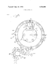
- FIGS. 1, 2 and 4 respectively represent top and partly broken-away, front and rear end views illustrating overall details of the improved feed mechanism and gunoperating system of the present invention, as it may be applied particularly to a manually-operated, non-firing model of the inventive gun system;
- FIG. 3 is a longitudinal sectional view, partly brokenaway, showing additional details of the feed mechanism and gun-operating system of FIG. 1;
- FIG. 5 is a second rear end view, in diagrammatic form, illustrating still further details of the inventive ammunition feed system
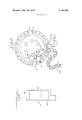
- FIG. 6 is another diagrammatic rear end view, somewhat similar to that of FIG. 5, but showing details of a modified form of the inventive feed mechanism, as it may be particularly applied to a firing model of the gun system of the present invention
- FIG. 7 is an additional rear end view, partly schematic, depicting details of the unique gear train used to power the main drive cam, and the delinking/feeder assembly, particularly as it may be applied to the firing form of the inventive gun;
- FIGS. 8 and 9 respectively represent side elevational and top views of the endless belt-type of ammunition conveyor system used with, and, in particular, as a part of the non-firing form of the present feed mechanism and gun system of FIGS. l-4;
- FIG. 10 is a cross-sectional view, taken about on line l0-10 of FIG. 8, showing further details of the inventive conveyor system;
- FIG. 11 is a fragmentary and partly broken-away view, looking in the direction of the arrow A in FIG. 10, depicting additional details of the gear/sprocket drive system of FIGS. 8-10 and used with the non-firing gun model of the invention;
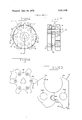
- FIG. 12 is an overall assembly view of the novel transfer sprocket of the present invention.
- FIG. 13 is a cross-sectional view, taken about on line 13-13 of FIG. 12, illustrating further details of the inventive transfer sprocket;
- FIG. 14 is a plan view, more clearly showing the precise configuration of the transfer sprocket component of the overall assembly of FIGS. 12 and 13;
- FIGS. 15 and 16 respectively represent top and side elevational views, illustrating details of the novel ammunition round-holding pawl mechanism component of the overall assembly of FIGS. 12 and 13;
- FIGS. 17, 18 and 19 are rear end, longitudinal and front end views, respectively, of a novel internal cam device used with, and to actuate the pawl mechanism of FIGS. 15 and 16 between its operative, roundholding and inoperative positions; and
- FIGS. 20, 21, 22, 23 and 24 respectively depict in diagrammatic form representative steps involved in the overall flow of ammunition during operation of the present feeder mechanism and gun system.
- the non-firing test model of the new and improved ammunition feeder mechanism and gun system of the present invention is indicated generally at 10 as consisting in part of a cluster of six barrels 11 held in a fixed and non-rotating relation around the gun axis 10a (Note FIG. 2) by means of the barrel-support ways at 12.
- a separate bolt is provided for each barrel 11, as has been depicted at 13 and 13a, respectively, in FIG. 3 for two of the said bolts.
- the gun system 10 further includes a receiver 14 (FIG.
- Drive cam 15 is specifically designed to orbit or rotate generally around, and relative to the gun and, in particular, the receiver 14 one revolution every six gun cycles or, in other words, 60 per cycle. In thus rotating, the said main drive cam 15 automatically actuates in successive order each of the aforementioned plurality of six bolts, as at 13 and 13a, between their forward, firing chamber-locking position and their aft, non-firing position.
- drive cam 15 incorporates in the appropriate portion of the wall surface thereof an arcuate-shaped slot, as depicted at 18 in FIG.
- the bolts, as at 13 and 13a have been operated in successive order to their aft positions by use of the main drive cam 15, they are then in the proper location so as to ensure the acceptance and retention within the extraction groove of each bolt the particular incoming round being fed thereinto by the novel feeder mechanism of the present invention, in the specific manner to be further described hereinafter, for its subsequent ramming in the particular firing chamber and extraction therefrom.
- the main drive cam 15 incorporates a flange portion 15a which acts as an inner bearing race.
- stationary gear 16 meshes with an identical pair of Ila-inch pitch diameter pinions, indicated at 20 and 21, which pinions 20 and 21 also mesh with each other.
- a third l /4-inch pitch diameter pinion, at 22, is located between, and also meshes with the pinions 20 and 21.
- the said third pinion 22 does not mesh with the stationary gear 16 and, therefore, during gun operation, is entirely free to rotate about its own axis in a direction opposite to that of the pinions 20 and'21.
- Each of the aforesaid pinions 20, 21 and 22 are respectively rigidly mounted on, or pinned to the aft end of a relatively elongated, feed mechanism-sprocket-operating shaft, indicated respectively at 23, 24 and 25 in FIGS. 1 and 4, for example.
- the opposite ends of the said shafts 23, 24 and 25 are respectively keyed into three sprockets; namely, a three-tooth feed sprocket at 26, a six-tooth transfer sprocket at 27 and a three-ejection sprocket at 28.
- These sprockets form a principal portion of the inventivefeed mechanism.
- the respective assemblies comprised of the pinions 20, 21 and 22, the shafts 23, 24 and 25, and the sprockets 26, 27 and 28 are rigidly mounted or assembled to, and thus rotate with the main drive cam during operation of the latter.
- the functions of the sprockets 26, 27, 28 are to provide the positive control, and facilitate the flow of ammunition within the present gun system 10 in a new and improved manner to be described hereinafter in detail.
- FIGS. 3 and 4 An additional important feature of the novel feed mechanism of the present invention resides in the provision of a unique ring-like squirrel cage, indicated at 29 in FIGS. 3 and 4, for example, which squirrel cage 29 is supported on, and revolvable relative to, the outside diameter or circumference of the main drive cam 15, as shown.
- Assembled to the cage 29 are a total of 24 altered socket head cap screws equally spaced at 15 intervals on a 5 l3/16-inch pitch diameter, which screws have been indicated generally at 30 in FIGS. 3 and 4, for example.
- the enlarged heads 30a of the said screws 30 act as an internal/external gear through which driving torque is transmitted during gun'operation. The threads of these screws have been removed from that portion of the screw body, indicated at 30b in FIG.
- each round near its center of gravity, denoted generally by the phantom line indicated at 31 (FIG. 3), is left open so that the various sprockets 26, 27, 28 of the inventive feed system may have free access to act upon the rounds for accomplishing their several functions involved in the previously-noted even flow of ammunition.
- the above-referred to squirrel cage 29, which may be fabricated from a bronze bearing material, is specifically designed to rotate around the gun 30 per gun cycle in the same direction as the drive cam 15 which is, however, rotating around the receiver 14 at a rate twice as fast or 60 per cycle, as has been previously noted.
- the squirrel cage 29- has a'total of 24 feed spaces formed between adjacently mounted, roundseparator screws 30, with every second feed space being actually utilized during the feeding of rounds into the gun and every alternate space being used to receive the rounds being extracted from the gun.
- the outer diameter or circumference of the cage 29 rotates within a stationary housing 32, which housing also acts as a rear guide means for the rounds.
- the aforementioned feeder, transfer and ejection sprockets 26, 27 and 28, previously described as being rigidly mounted to the drive cam 15, along with their supporting shafts 23, 24 and 25 and pinions 20, 21 and 22, may be specifically affixed to, and for simultaneous rotation with, the said drive cam 15 by being particularly assembled to an inner round guide means consisting of interconnected front and rear internal guide elements, indicated at 33 and 35 in FIG. 3, which guide elements are formed into an internal plate and are actually bolted to the flange 15a of the drive cam 15 for simultaneous rotation therewith.
- the said internal and external plates respectively guide on the neck and shoulder portions of the rounds.
- the inner round guide means comprising the above-noted front and rear internal guide elements 33 and 35 and, of course, the drive cam 15 to which they are assembled orbits the present gun and, in particular, the barrel cluster 11 thereof in a clockwise direction as viewed from the rear of the gun
- the feed and ejection sprockets 26 and 28 carried thereby are caused to simultaneously rotate in the same clockwise direction relative to the inner round guide means 33, 35, or, in other words 120 60 relative to the stationary gun.
- the function of the said transfer sprocket 27, on its rotation, is to program the flow of either live rounds for the firing model or dummy rounds for the manually-operated test model of the present gun by engaging with, and transferring these rounds from the squirrel cage 29 to the three-tooth feed sprocket 26.
- the latter has been uniquely fitted with three sets of round-holding or gripping pawls respectively indicated at 37, 38 and 39 in FIG. 12. As is depicted specifically in FIG.
- transfer sprocket 27 actually consists of an assembly that includes a pair of spaced-apart transfer sprocket-plate members, at 40 and 41, which plate members 40 and 41, each incorporate a plurality of six teeth indicated generally at 43 (Note FIGS. 12 and 14). Positioned in interposed relation between the members 40 and 41 are the previously-noted pawl members 37, 38 and 39.
- FIG. 14 it is clearly seen that the circumference or periphery of each of said plate members, as for example plate member 40, incorporates a plurality of arcuate-shaped round-receiving and recessed seat portions at 42, within which the rounds being engaged are precisely fitted during operation of the inventive transfer sprocket 27.
- pawl member 15 and 16 consists of a pair of separate pawl members, as indicated generally at 45 and 46 in the aforementioned FIG. 15, which are each mounted for limited pivotal movement between, and relative to, the transfer sprocket-plate members 40 and 41, by means of a screw member such as that indicated at 47 in FIG. 13. Said screw member 47 engages in an opening provided therefor in each of the aforesaid plate portions 40 and 41 and in the said pawl members, such as that indicated at 46b in FIG. 15 for the pawl member 46. A similar opening 45b is provided for the same purpose in the pawl member 45.
- the pawl members 45 and 46 may be easily pivoted between a first, inner position in which the jaws 45c and 460 located on the upper ends thereof are placed in a gripping relation with the round being fed into the gun and engaged by the transfer sprocket 27, and a second, outer position in which the said jaws 45c and 460 have been spread apart a relatively small amount or degree.
- the pawl member 45 has been formed with an intermediately-disposed projection or projecting knob-like element 45a on its inner surface (Note FIG.
- an internal, pawl-operating cam member is used for all three sets of pawls 37, 38 and 39.
- the said internal cam 44 mounts about the transfer sprocket shaft 24 and it orbits around the non-rotating barrel cluster 11; however, it does not rotate with the transfer sprocket 27.
- Said internal cam 44 incorporates a main cam body portion 48, an open aft end portion 49 having an inner opening 50 for receiving the shaft 24 therethrough and a forward end portion having a pair of inwardly-projecting cam surfaces thereon; namely, a first, upper cam surface 51 and a second, lower cam surface 52, as is viewed in FIG. 18, for example.
- the second, lower cam surface 52 When mounted in position on the shaft 24, and when the drive cam 15, the inner round guide means 33 and 35 and, of course, the transfer sprocket 27 have been actuated in orbit about the barrel cluster 11 during the feeding of rounds into the gun, the second, lower cam surface 52 (FIG. 18, for example) has engaged with the inside of the lower surface portion 45d of the pawl member 45 (Note FIG.
- a test conveyor system depicted in FIGS. 8-11, inclusive, was used in actual tests to manually operate the present gun system or mechanism 10 with the use of dummy rounds for successfully demonstrating the feasibility of the invention.
- Said conveyor system which is indicated generally at 53, incorporated an endlesstype of ammunition belt that included a total of forty links, indicated at 54, spaced at one-inch intervals.
- This endless ammunition belt-conveyor system 53 has the effect of simulating a continuous flow ammunition belt. Power to operate this system may be, and during tests thereof was, supplied by means of a hand crank (not shown) inserted into the hub 55 of a 2.550 -inch pitch diameter'main, ammunition belt or conveyor drive gear at 56 (Note FIG. 8, for example) located at the center of the conveyor.
- One clockwise revolution of the said main drive gear 56 conveys six rounds into the inventive feeder system, as will be further explained hereinafter.
- Said main, ammunition belt-drive gear 56 meshes with two 1.700-inch PD gears, indicated at 57 and 58, respectively, to maintain proper register and to transmit torque.
- a l.9l()-inch PD main drive, sprocket 59 is mounted to the drive shaft 60 of the main conveyor drive gear 56, as is seen particularly in FIG. 10.
- the said sprocket 59 is clearly depicted in the latter figure as straddling the inside of the conveyor belt comprised of the links 54 and is instrumental in moving said belt in the clockwise direction (Note FIG.
- the sprocket 59 drives against 3/32-inch-diameter by %-inch-long pins pressed into the links 54 and which are located at -inch intervals in the ammunition belt.
- the rounds carried thereby are engaged by a four-tooth ammunition feed sprocket, indicated at 61, and a round guide 62 (Note particularly FIGS. 8 and 11) which controls, guides and places the rounds between the previously-described socket-head cap screws 30 assembled to the squirrel cage 29 of the inventive feeder mechanism.
- This process is reversed when the rounds are being ejected from the present feeder system, by use of a four-tooth ejection sprocket at 63 (Note FIGS. 9 and 11), which replaces the rounds in the conveyor system 53.
- sprockets 64 and 65 Located directly behind the 1.700-inch PD gears 57 and 58 on the same shafts mounting the latter are eighttooth sprockets 64 and 65 (Note FIG. 8) which mesh with the heads 30a of the sprocket-head cap screws 30 that are assembled to the squirrel cage 29.
- sprockets 64 and 65 engage the screw heads adjacent the bottom portion of the squirrel cage 29.
- Driving torque which may be easily applied by a handoperated crank (not shown) that may be keyedinto the main conveyor drive gear 56, as noted hereinbefore, is transmitted through the engagement between the said eight-tooth sprockets 64, 65 and the heads 30a of the squirrel cage-screws 30 to the feeder mechanism and gun system of the present invention.
- the said main conveyor drive gear 56 would be rotated clockwise, resulting in the simultaneous rotation of the drive sprockets 64 and 65 counterclockwise and i in the rotation of the squirrel cage 29 in a clockwise direction a total of 30 per gun cycle, as noted hereinbefore.
- the endless ammunition belt-conveyor system 53 was mounted in appropriate position to-the present feeder mechanism and gun system 10, during the manual operation of the latter.
- FIG. 5 The basicsequence of operation of the present feeder mechanism and gun system 10 of the invention may be illustrated in specific connection with FIG. 5, for example.
- a total of 10 of the previously-referred to 40 rounds of ammunition are indicated generally at 66 as being in the process of being fed from the conveyor system 53 into the proper feed spaces in the squirrel cage 29.
- the conveyor system 53 is of course being manually operated by the clockwise rotation of the drive gear 56 (FIG. 8), and interconnecting sprockets, as previously described, in synchronism with the clockwise rotation of the main drive cam 15 by the engagement between the squirrel cage-screws 30 and the eight-tooth sprockets 64 and 65.
- the above-described rotation of the transfer sprocket 27 results from the driving interconnection between the teeth of six-tooth cog wheel 67 and the heads 30a of the squirrel cage-screws 30.
- the said transfer sprocket 27, and the threetooth feed and ejection sprockets 26 and 28 are all assembled to the inner round grid means 33, 35 rigidly mounted to the flange 15a of the main drive cam 15 for simultaneous rotation therewith.
- the rotation of the main drive cam 15 by the aforementioned manual rotation of the squirrel cage 29, through means of the interconnecting cog wheel 67, which is mounted to the transfer sprocket shaft 24 (Note FIG. 3, for example), likewise effects the automatic rotation of the feed,
- each bolt 13 in its proper turn, becomes operative by means of the previously-described engagement of its bolt operating lug member 19 in the drive cam-groove 18 (Note FIG. 3) to ram its respective round 66 in the appropriate gun barrel-firing chamber.
- the further rotational operation of the drive cam 15 naturally effects the successive extraction of the expended cartridge or dummy round.
- the aforementioned three-tooth ejection sprocket 28 is operative to automatically return the dummy round, as for example that indicated at 66a in FIG. 5, to a position in the squirrel cage 29 between an adjacent pair of screws 30 that would be in an alternate relation with the spaces formed between a similar set of screws 30 between which the rounds 66 were originally placed, as has been hereinbefore explained.
- the continued manual operation of the main conveyor system 53 to maintain the clockwise rotation of the squirrel cage 29 would be operative to transport the expended or dummy cases, as at 66a, which are placed in the squirrel cage 29 in alternate relation with the placement therein of the originally placed rounds 66, to a lower position, as seen at 66b, where it is automatically engaged and removed from the squirrel cage 29 by the four-tooth ejection sprocket at 63.
- the latter because of its appropriate position relative to the conveyor system 53 is being automatically operated in counterclockwise rotation by the same manual rotation of the main drive gear 56 to replace the expended or dummy cases 66 in the same ammunition belt from whence they, as dummy rounds, were originally removed.
- FIG. 20 which represents the initial step or position No. 1 of the ammunition flow steps involved in the operation of the present gun system 10, either the firing or non-firing model thereof, a total of three live rounds have already been fed from the ammunition belt by the combined delinker/feeder assembly 68 to a position of engagement by the fourtooth feed sprocket at 61.
- Round No. 1 is about to be placed in position between two of the screws 30 formed or assembled to the inner circumference of the squirrel cage 29, and a total of ten rounds have been illustrated in the process of being fed into the present feed mechanism.
- the round guide 62 assists in this operation and the previously-noted four-tooth ejection sprocket is shown at 63.
- the operation of the squirrel cage 29 is identical to that previously described and, accordingly, the squirrel cage 29 rotates in a clockwise direction at the previously-noted rate of 30 per gun cycle and, on the beginning of gun operation, automatically feeds the said live rounds in a clockwise direction until they are successively engaged by the aforementioned six-tooth transfer sprocket 27.
- the latter sprocket, along with the three-tooth feed and ejection sprockets 26 and 28 are, of course, assembled to the drive cam 15, as noted before, and, as such, are also automatically rotating, the rotation of the transfer sprocket 27 being counterclockwise and that of the other two being clockwise.
- FIG. 21 which represents position No.
- the said transfer sprocket 27 is shown having initially engaged and removed round No. 6 from the appropriate feed space in the squirrel cage 29, and about to transfer the same to the three-tooth feed sprocket 26.
- round Nos. 1, 2, 3, 4 and 5 have not yet been acted upon and engaged by the said transfer sprocket 27 and are still held in their appropriate feed spaces in the squirrel cage 29.
- round No. 6 is the first to be engaged by the transfer sprocket 27, followed in order by round Nos. 5, 4, 3, 2 and 1. Thereafter, round Nos. 12, ll, 10, 9, 8 and 7 are engaged in that order.
- the firing gun may be further improved by increasing the pitch diameter of the transfer sprocket 27 and eliminating the aforementioned feed and ejection sprockets, as at 26 and 28.
- This modified design has been illustrated generally at 72 in the schematic view of FIG. 6 and in the detailed illustration of the power-transmitting, gear train means of FIG. 7.
- the gun design 72 includes the squirrel cage at 69 (Note FIG. 6), again, equipped with a plurality of round-separator means, represented by the buttons at 70 and orbiting the stationary barrel cluster 11.
- Squirrel cage 69 is modified over that of the previously-described squirrel cage 29 by being equipped with an enlarged gear on its periphery, as is indicated at the reference numeral 84 in FIG. 7, which gear 84 forms part of the gear train, to be hereinafter described in detail, that is utilized to drive the modified gun system 72.
- An enlarged pitch diameter transfer sprocket, indicated at 73 (FIG. 6) is again equipped with three sets of round-holding pawls, indicated generally at 74, and again rotates counterclockwise to engage rounds being fed into the proper, alternate feed spaces formed by, and between, the screws 70 assembled to the cage 69.
- the transfer sprocket 73 successively feeds the rounds '76 directly into a captive position in the heads of the bolts of each of the barrels of the cluster 11, of course, with the assistance of the inner round guide 77 that is affixed, as described hereinbefore, to the main drive cam 78 (FIG. 7) for rotation therewith.
- the live rounds being fed into the modified gun system 72 are depicted at L and the fired rounds at F.
- a drive motor assembly, indicated at 75 in FIG. 7, is used to operate the main drive cam 78.
- the motor drive assembly 75 which may be mounted adjacent to the bottom right-hand side of the gun, may include a drive pinion 79 mounted on its motor-drive shaft (not shown) that meshes with an intermediate gear 80 that meshes, in turn, with the larger gear 81 of a pair of coupled gears mounted for simultaneous rotation together on the same shaft, the smaller gear thereof being indicated at 82.
- the larger gear 81 meshes with a relatively large peripheral or circumferential gear, indicated at 83 as being formed on the drive cam 78 or, in particular, on the inner round guide means 78a affixed for rotation with the drive cam 78.
- the smaller gear 82 is in mesh with another gear, indicated at 84, of a larger circumference than that of the drive cam-gear 83 and constituting a circumferential drive gear formed on the squirrel cage 69.
- the combined delinking feeder assembly 68 is indicated in the aforementioned FIGS. 6 and 7 as being in the process of feeding a number of prelinked rounds of ammunition into the inventive feeder mechanism.
- operation of the delinking feeder assembly is effective to push the live rounds forward, in this case, for a distance of l inches out of their links, whereupon the separated links are thereafter ejected from the bottom, as is generally depicted by the arrow A.
- the precise means by which this initial push forward of the rounds 76 is not specifically illustrated, since the details thereof are unimportant to, and do not effect the specific operation of the inventive feeder mechanism. It is considered sufficient to say that, after being delinked, the live rounds 76 are thereafter placed into their proper feed spaces in the squirrel cage 69 (Note FIG. 6).
- the combined delinking feeder assembly 68 incorporates a pair of driven gears coupled together for simultaneous rotation on the same shaft and indicated respectively at 85 and 86.
- the gear 85 which is the larger of the two, meshes with, and is automatically driven by, the squirrel cage-gear 84, whereas, the smaller gear 86, coupled thereto by being mounted on the aft end of the same shaft, is, in turn, in mesh with a larger gear 87 that forms a part of the delinking feeder assembly 68 and is mounted for simultaneous rotation with an eight-tooth delinking feeder assembly-sprocket at 88.
- the rotating eight-tooth sprocket 88 thus engages the live and linked rounds of ammunition, as at 76, and feeds clockwise until these rounds, after having been pushed forward and delinked are automatically engaged by another feeder-sprocket at 89, which is, at the same time, being rotated in a counterclockwise direction by means of the engagement between the previously-noted gear 87 and still another gear at 90 that is mounted on one end of a shaft to the opposite end of which is affixed the feedersprocket 89.
- a new and improved weapon system has been developed by the present invention by the use of a unique mechanism that circulates around a stationary barrel cluster and, in timed sequence by using geared connecting means between major ammunition feed and operating-gun components, successively feeds, loads, fires and clears each barrel in turn, while, simultaneously, and automatically replenishing the fired ammunition.
- a combined ammunition feed mechanism movably positioned on the gun receiver for rotation in orbit about the fixed barrel cluster, and gun-operating system comprising; a boltoperating means adjustable in position and interconnected with the operating lug member of, and thereby successively moving the bolt mechanism for each barrel between its forward, firing position and its aft, round-extracting and ejecting position; an intermediately-positioned, rear round guide incorporating a series of evenly-spaced ammunition-feed spaces for receiving and supporting the rear end portions of a predetermined number of rounds being successively fed thereinto; ammunition belt means adapted to supply rounds to said rear round guide-feed spaces; first, main, round-feeding means operably associated with and adjustable in position to remove rounds from the belt and place them in every other one of said feed spaces; an inner round guide slidably supporting the forward end portions of the rounds, and attached in a forwardlydisposed relation to
- said bolt-operating means comprises a main, drive cam mounted for rotation relative to the gun receiver; said cam incorporating a slotted surface extending from an intermediately-disposed slotted portion on the top surface thereof inwardly, and downwardly around its circumference towards the breech of the gun; the said bolt-operating lug member of each of said bolt mechanisms being slidably engaged within said drive camslotted surface.
- said rear round guide comprises a squirrel cage consisting ofa circular ring positioned on, and rotating relative to said inner round guide.
- the ammunition-feed spaces of said squirrel cage may be formed by the installation thereto of a plurality of socket-head cap screws extending from the head portions thereof disposed along the aft side of said circular ringsquirrel cage inwardly through the circumference thereof to projecting, forwardly-disposed screw portions arranged along the front side of said ring and respectively acting as round separator elements during the feeding of ammunition thereinto.
- said ammunition belt means comprises an endless beltconveyor system; and said gear train means comprises a manually-actuated, main drive gear interconnected with, and adapted to rotate said endless belt-conveyor system in a predetermined direction for the continuous feeding of ammunition.
- said first, main, round-feeding means comprises a fourtooth feed sprocket mounted on a shaft interconnected with, and manually-operable by, said main drive gear of said gear train means, said four-tooth feed sprocket thereby automatically engaging and removing successiverounds from said endless belt-conveyor system for their placement in alternate feed spaces provided between said squirrel cage-screws.
- said gear train-shaft further mounting an eight-tooth sprocket engaging the head portions of the screws of, and thereby rotating said squirrel cage in orbit about the barrel cluster, simultaneously with the feeding of rounds by said four-tooth feed sprocket into the proper feed spaces formed between the projecting inner ends of said screws on the opposite side of said squirrel cage.
- said inner round guide further incorporates in assembled relation thereto a second, direct round-feeding means rotatable about its own axis in a direction opposite to that of said round-transfer means and engageable with each of the rounds being transferred thereby and placing said rounds in a captive position in the heads of each bolt mechanism, and round-ejection means rotatable about its own axis simultaneously with, and in the same direction as the second, direct round-feeding means for successively engaging and ejecting rounds being extracted from each gun barrel by said bolt mechanisms.
- said round-transfer, second, round-feeding and roundejeetion means respectively comprise a six-tooth transfer sprocket and three-tooth feed and ejection sprockets assembled to said inner round guide for orbit about the barrel cluster with the rotation of said main drive cam; and said gear train means comprises a main, stationary gear fixedly mounted on the gun receiver, a pair of pinions in mesh with each other and with said stationary gear, a third pinion in mesh with said pair of pinions, and sprocket-mounting shaft means respectively mounting said pinions and said sprockets on opposite ends thereof; said gear train means further comprising a cog wheel mounted to said drive cam and engaging the screws of, and thereby simultaneously rotating said squirrel cage in concert therewith.
- said gear train means comprises a first, peripheral gear formed on said main drive cam; a second, peripheral gear formed on said squirrel cage; and drive motor means adapted to be mounted to one side of the gun and incorporating interconnecting gear means of predetermined different sizes and respectively engaging said first and second peripheral gears to thereby rotate said main drive cam and said squirrel cage at selected different rates for each gun cycle.
Landscapes
- Engineering & Computer Science (AREA)
- General Engineering & Computer Science (AREA)
- Portable Nailing Machines And Staplers (AREA)
Abstract
A test model machine gun having an endless ammunition belt continuously moving during operation, a stationary multi-barrel cluster arranged about the gun axis and a combined feed and gunoperating mechanism including a squirrel cage automatically rotatable in orbit about the barrel cluster in synchronism with the moving belt and equipped with a series of ammunition feed spaces, a four-tooth feed sprocket geared to, and thus automatically operable therewith, for removing rounds from the moving belt for their placement in successive squirrel cage-feed spaces, and a bolt-operating drive cam rotatable within, and in simultaneous orbit with, the squirrel cage and incorporating transfer, feed and ejection sprockets automatically rotatable during orbit of the drive cam to respectively engage and transfer rounds from the squirrel cage, feed the transferred rounds to a captive position in the bolt heads and eject the rounds extracted by the bolts for subsequent positioning in alternate squirrel cage-feed spaces. A four-tooth ejection sprocket, geared to the four-tooth feed sprocket and to the drive cam, is simultaneously operative in sequence with rotation of the squirrel cage to engage the extracted rounds returned thereto and replace them in the moving belt.
Description
United States Patent [191 Stewart et al.
[ FEED SYSTEM FOR A NON-ROTATING MULTI-BARREL GUN [75] Inventors: Paul E. Stewart, Deerfield, Ill.; Dale M. Davis, Freeport, Fla.
[73] Assignee: The United States of America as represented by the Secretary of the Air Force, Washington, DC.
[22] Filed: Mar. 10, 1972 [21] Appl. No.: 233,595
[52] US. Cl. 89/11, 89/33 CA Primary Examiner-Stephen C. Bentley Attorney-Harry A. Herbert, Jr. et a].
[57] ABSTRACT A test model machine gun having an endless ammuni- June 26, 1973 tion belt continuously moving during operation, a stationary multi-barrel cluster arranged about the gun axis and a combined feed and gun-operating mechanism including a squirrel cage automatically rotatable in orbit about the barrel cluster in synchronism with the moving belt and equipped with a series of ammunition feed spaces, a four-tooth feed sprocket geared to, and thus automatically operable therewith, for removing rounds from the moving belt for their placement in successive squirrel cage-feed spaces, and a bolt-operating drive cam rotatable within, and in simultaneous orbit with, the squirrel cage and incorporating transfer, feed and ejection sprockets automatically rotatable during orbit of the drive cam to respectively engage and transfer rounds from the squirrel cage, feed the transferred rounds to a captive position in the bolt heads and eject the rounds extracted by the bolts for subsequent positioning in alternate squirrel cage-feed spaces. A fourtooth ejection sprocket, geared to the four-tooth feed sprocket and to the drive cam, is simultaneously operative in sequence with rotation of the squirrel cage to engage the extracted rounds returned thereto and replace them in the moving belt.
10 Claims, 24 Drawing Figures Patented June 26, 1973 9 Sheets-Sheet l Patented June 26, 1973 9 Sheets-Sheet 2 Patented June 26, 1973 9 Sheets-Sheet I.
Patented June 26, 1973 3,741,069
0 Sheets-Sheet 4.
Patented June 26, 1973 9 Sheets-Sheet b Patented June 26, 1973 3,741,069
9 Sheets-Sheet 6 Patented June 26, 1973 3,741,069
9 Sheets-Sheet 7 Patented June 26, 1973 9 SheetsSheet 8 Patented June 26, 1973 3,741,069
9 Sheets-Sheet 9 FEED SYSTEM FOR A NON-ROTATING MULTI-BARREL GUN BACKGROUND OF THE INVENTION This invention relates to, and constitutes an improvement over, the Gatling-type of rapid fire machine gun.
The prime high rate of fire guns in current use by the U. S. Air Force are the 7.62 mm minigun and the 20 mm Vulcan cannon. Both of these weapons incorporate six gun barrels operating on the well-known Gatling principle in which the multi-barrels thereof rotate together in a cluster. However, although this technique has resulted 'in a tremendously increased fire power that has been placed on the selected target area with significant effect; nevertheless, this method of fire whereby the multiple gun barrels are rotated together in a cluster has produced an inherent or built-in degree of inaccuracy resulting from the natural imparting of a tangential velocity to the fired projectiles upon their exit from the muzzles of the barrels. This velocity is, of course, proportional to the rate of rotation being applied to the barrel cluster. Obviously,-therefore, for the variable rate of fire resulting from changeable barrel cluster rotational velocities, the corresponding change in the tangential velocities thereof results in different projectile impact coordinates for each rate of tire. As a consequence, tactical fighter pilots, though attacking their selected targets with good success, have, nevertheless, encountered considerable difficulty because of the aforementioned built-in error inherent in the rotating multiple gun barrels.
The non-rotating multi-barrel gun of the present invention was developed as a direct result of a program to produce a multi-barrel, high rate of fire gun having increased accuracy. Moreover, the objective of this program was to design an effective feed mechanism and gun firing system which would be inherently capable of providing fora more positive control of the flow of ammunition within, and throughout the weapon systern, in unique and automatic concert with the operation of the gun firing mechanism. Essentially, the selected design of the present invention, and the initial description thereof to beset forth hereinafter, centers around a manually-operated, and non-firing test model utilizing an endless-type of continuously-rotating ammunition belt-conveyor system in which, for purposes of testing the inventive concept, a supply of some 40 dummy rounds of ammunition were successfully recirculated throughout the gun model from their point of removal from the endless belt to their return thereto. In this connection, a firing model employing basically the same inventive concept with slight modifications was also developed and is described hereinafter.
A number of non-rotating, multi-barrel gun and ammunition feed systems were developed and discarded in favor of the present arrangement. These prior developments included a six-barrel gun having a main drive cam and a rotatable ring-like squirrel cage in which was formed a total of 24 feed spaces for receiving the indicated number of rounds. Two sprockets were employed; namely, a feed sprocket and an ejection sprocket which, attached to a round guide, formed a so-called rotating spider assembly. However, this alternative was not selected for the reason that there proved to be too abrupt a change in velocity when the feed sprocket removed a round from the squirrel cage and placed it in the bolt head for its subsequent ramrning thereby into the particular firing chamber. Furthermore, since the squirrel cage revolved once for every four rounds fired, only four rounds could be fed by this system during a complete firing cycle, instead of the six rounds that would be required for the satisfactory use of the six-barrel system.
Additional investigation into modified feeding means resulted in the suggestion to place an idler sprocket next to, and in mesh with, each of the feed and ejection sprockets, and also to reverse the direction of rotation of the squirrel cage relative to that of the spider assembly. To accommodate the two idler sprockets, the pitch diameter of the squirrel cage had to be increased; however, further study of this system revealed both a tendency of the rounds to jam, and difficulty was experienced in the feeding of rounds into the feed sprocket.
In an effort to alleviate the above-noted problems created by the use of idler sprockets, the latter were placed as close as possible to each other, and the feed and ejection sprockets were moved to the outside of the idler sprockets, whereas in the initial proposal the idler sprockets had been positioned on the outside. As in the first arrangement, however, this system was also discarded because it resulted in the main drive cam, which controlled the axial position of the bolts, having a drive and return angle or slope of 55, whereas, a maximum of 45 is considered acceptable for smooth operation.
Another alternate design considered consisted of three sprockets; namely, a three-tooth feed sprocket, a three-tooth ejection sprocket, and a six-tooth idler sprocket mounted therebetween and in mesh therewith. The idler sprocket serves two functions. First, it removes rounds from the squirrel cage and places them in the feed sprocket, and, secondly, it accepts expended cases from the ejection sprocket and returns them to the squirrel cage. There is no dead space, as in other alternatives, between the sprockets, and thus a smoother operation is assured. Furthermore, there is ample space so that the main drive cam having a slope of 45 or less can be utilized. This design, which is considered an acceptible alternative to the improvement of the present invention, was composed of a seven-barrel cluster and a squirrel cage having 28 feed spaces. In this connection, the preferred embodiment of the present invention, to be described hereinafter in the following summary and detailed description, consists of a sixbarrel design with a squirrel cage equipped with 24 feed spaces.
The objective of the specific arrangement of the present gun system was to develop a gun having the demonstrated advantages of the Gatling principle and yet, by using a stationary barrel cluster, improved accuracy was achieved. In this regard and as has been previously indicated, to prove out the principle of operation of the improvement of the present gun, the description hereinafter is made initially in connection with a nonfiring gun model that was actually designed, fabricated, and successfully demonstrated to establish the feasibility of the inventive concept.
SUMMARY OF THE INVENTION This invention resides briefly in a new and unique ammunition feed mechanism and gun firing system acting in concert with each other,and which is initially described as being embodied in a non-firing test model consisting principally of a stationary six-barrel cluster,
an endless-type of ammunition belt that, during operation, is continuously moved by manually-operated means, a rotatable squirrel cage that orbits the stationary gun barrel cluster and which incorporates a total of 24 ammunition-feed spaces, a first, four-tooth feed sprocket manually operable in concert and simultaneously with, the ammunition belt for automatically removing rounds of ammunition, as by stripping from the belt and placing them in the feed spaces of the squirrel cage, a six-tooth transfer sprocket automatically removing rounds from the squirrel cage and placing them in a second, three-tooth feed sprocket that, in turn, feeds these rounds into a captive position in the heads of the bolts for each gun barrel, and a three-tooth ejection sprocket for ejecting rounds being extracted from each firing chamber and returning the same to the squirrel cage. A four-tooth ejection sprocket, geared to the four-tooth feed sprocket, and thus simultaneously rotating therewith, automatically engages the extracted rounds in the squirrel cage and replaces them in the belt. It is noted that, as previously suggested, the rounds used in the successful testing of the non-firing model of the inventive gun were all dummy rounds that were recirculated throughout the system in a most effective manner.
Inherent objects and other advantages of the invention will become readily apparent from the following disclosure taken in connection with the accompanying drawings, in which;
BRIEF DESCRIPTION OF THE DRAWINGS FIGS. 1, 2 and 4 respectively represent top and partly broken-away, front and rear end views illustrating overall details of the improved feed mechanism and gunoperating system of the present invention, as it may be applied particularly to a manually-operated, non-firing model of the inventive gun system;
FIG. 3 is a longitudinal sectional view, partly brokenaway, showing additional details of the feed mechanism and gun-operating system of FIG. 1;
FIG. 5 is a second rear end view, in diagrammatic form, illustrating still further details of the inventive ammunition feed system;
FIG. 6 is another diagrammatic rear end view, somewhat similar to that of FIG. 5, but showing details of a modified form of the inventive feed mechanism, as it may be particularly applied to a firing model of the gun system of the present invention;
FIG. 7 is an additional rear end view, partly schematic, depicting details of the unique gear train used to power the main drive cam, and the delinking/feeder assembly, particularly as it may be applied to the firing form of the inventive gun;
FIGS. 8 and 9 respectively represent side elevational and top views of the endless belt-type of ammunition conveyor system used with, and, in particular, as a part of the non-firing form of the present feed mechanism and gun system of FIGS. l-4;
FIG. 10 is a cross-sectional view, taken about on line l0-10 of FIG. 8, showing further details of the inventive conveyor system;
FIG. 11 is a fragmentary and partly broken-away view, looking in the direction of the arrow A in FIG. 10, depicting additional details of the gear/sprocket drive system of FIGS. 8-10 and used with the non-firing gun model of the invention;
FIG. 12 is an overall assembly view of the novel transfer sprocket of the present invention;
FIG. 13 is a cross-sectional view, taken about on line 13-13 of FIG. 12, illustrating further details of the inventive transfer sprocket;
FIG. 14 is a plan view, more clearly showing the precise configuration of the transfer sprocket component of the overall assembly of FIGS. 12 and 13;
FIGS. 15 and 16 respectively represent top and side elevational views, illustrating details of the novel ammunition round-holding pawl mechanism component of the overall assembly of FIGS. 12 and 13;
FIGS. 17, 18 and 19 are rear end, longitudinal and front end views, respectively, of a novel internal cam device used with, and to actuate the pawl mechanism of FIGS. 15 and 16 between its operative, roundholding and inoperative positions; and
FIGS. 20, 21, 22, 23 and 24 respectively depict in diagrammatic form representative steps involved in the overall flow of ammunition during operation of the present feeder mechanism and gun system.
DESCRIPTION OF THE PREFERRED EMBODIMENT Referring generally to the drawings and, in particular, to FIGS. 1-4 thereof, the non-firing test model of the new and improved ammunition feeder mechanism and gun system of the present invention is indicated generally at 10 as consisting in part of a cluster of six barrels 11 held in a fixed and non-rotating relation around the gun axis 10a (Note FIG. 2) by means of the barrel-support ways at 12. Naturally, a separate bolt is provided for each barrel 11, as has been depicted at 13 and 13a, respectively, in FIG. 3 for two of the said bolts. The gun system 10 further includes a receiver 14 (FIG. 3), a main drive cam 15, and a 2r-inch pitch di ameter stationary gear 16 affixed on the aft end of the receiver 14 by a self-locking pin 17. Drive cam 15 is specifically designed to orbit or rotate generally around, and relative to the gun and, in particular, the receiver 14 one revolution every six gun cycles or, in other words, 60 per cycle. In thus rotating, the said main drive cam 15 automatically actuates in successive order each of the aforementioned plurality of six bolts, as at 13 and 13a, between their forward, firing chamber-locking position and their aft, non-firing position. For this purpose, drive cam 15 incorporates in the appropriate portion of the wall surface thereof an arcuate-shaped slot, as depicted at 18 in FIG. 3, in which slot 18 may be slidably engaged or positioned the respective bolt-operating lug members, as at 19, which are formed on the periphery of the bolts, as at 13 and 13a. When the bolts, as at 13 and 13a, have been operated in successive order to their aft positions by use of the main drive cam 15, they are then in the proper location so as to ensure the acceptance and retention within the extraction groove of each bolt the particular incoming round being fed thereinto by the novel feeder mechanism of the present invention, in the specific manner to be further described hereinafter, for its subsequent ramming in the particular firing chamber and extraction therefrom. The main drive cam 15 incorporates a flange portion 15a which acts as an inner bearing race.
The above-referred to stationary gear 16 meshes with an identical pair of Ila-inch pitch diameter pinions, indicated at 20 and 21, which pinions 20 and 21 also mesh with each other. A third l /4-inch pitch diameter pinion, at 22, is located between, and also meshes with the pinions 20 and 21. However, the said third pinion 22 does not mesh with the stationary gear 16 and, therefore, during gun operation, is entirely free to rotate about its own axis in a direction opposite to that of the pinions 20 and'21. Each of the aforesaid pinions 20, 21 and 22 are respectively rigidly mounted on, or pinned to the aft end of a relatively elongated, feed mechanism-sprocket-operating shaft, indicated respectively at 23, 24 and 25 in FIGS. 1 and 4, for example. The opposite ends of the said shafts 23, 24 and 25 are respectively keyed into three sprockets; namely, a three-tooth feed sprocket at 26, a six-tooth transfer sprocket at 27 and a three-ejection sprocket at 28. These sprockets form a principal portion of the inventivefeed mechanism. In this connection, the respective assemblies comprised of the pinions 20, 21 and 22, the shafts 23, 24 and 25, and the sprockets 26, 27 and 28 are rigidly mounted or assembled to, and thus rotate with the main drive cam during operation of the latter. The functions of the sprockets 26, 27, 28 are to provide the positive control, and facilitate the flow of ammunition within the present gun system 10 in a new and improved manner to be described hereinafter in detail.
An additional important feature of the novel feed mechanism of the present invention resides in the provision of a unique ring-like squirrel cage, indicated at 29 in FIGS. 3 and 4, for example, which squirrel cage 29 is supported on, and revolvable relative to, the outside diameter or circumference of the main drive cam 15, as shown. Assembled to the cage 29 are a total of 24 altered socket head cap screws equally spaced at 15 intervals on a 5 l3/16-inch pitch diameter, which screws have been indicated generally at 30 in FIGS. 3 and 4, for example. The enlarged heads 30a of the said screws 30 act as an internal/external gear through which driving torque is transmitted during gun'operation. The threads of these screws have been removed from that portion of the screw body, indicated at 30b in FIG. 3, which projects inwardly into the feeder for three-fourths of an inch. In fact, the body portions 30b of alternately-disposed screws, which have been actually turned down until smooth, act as round-separator means by straddling the base of the rounds, when the latter have been fed into the gun. The inner portion of each round, near its center of gravity, denoted generally by the phantom line indicated at 31 (FIG. 3), is left open so that the various sprockets 26, 27, 28 of the inventive feed system may have free access to act upon the rounds for accomplishing their several functions involved in the previously-noted even flow of ammunition.
The above-referred to squirrel cage 29, which may be fabricated from a bronze bearing material, is specifically designed to rotate around the gun 30 per gun cycle in the same direction as the drive cam 15 which is, however, rotating around the receiver 14 at a rate twice as fast or 60 per cycle, as has been previously noted. The squirrel cage 29- has a'total of 24 feed spaces formed between adjacently mounted, roundseparator screws 30, with every second feed space being actually utilized during the feeding of rounds into the gun and every alternate space being used to receive the rounds being extracted from the gun. The outer diameter or circumference of the cage 29 rotates within a stationary housing 32, which housing also acts as a rear guide means for the rounds. In this connection, the aforementioned feeder, transfer and ejection sprockets 26, 27 and 28, previously described as being rigidly mounted to the drive cam 15, along with their supporting shafts 23, 24 and 25 and pinions 20, 21 and 22, may be specifically affixed to, and for simultaneous rotation with, the said drive cam 15 by being particularly assembled to an inner round guide means consisting of interconnected front and rear internal guide elements, indicated at 33 and 35 in FIG. 3, which guide elements are formed into an internal plate and are actually bolted to the flange 15a of the drive cam 15 for simultaneous rotation therewith. An external plate including the front and rear external guide elements 34 and 36, which are mounted to the stationary housing 32, completes the principal support for the front ends of the rounds, when the latter are fed into the gun. In particular, the said internal and external plates respectively guide on the neck and shoulder portions of the rounds.
With the foregoing arrangement, as the inner round guide means comprising the above-noted front and rear internal guide elements 33 and 35 and, of course, the drive cam 15 to which they are assembled orbits the present gun and, in particular, the barrel cluster 11 thereof in a clockwise direction as viewed from the rear of the gun, the feed and ejection sprockets 26 and 28 carried thereby are caused to simultaneously rotate in the same clockwise direction relative to the inner round guide means 33, 35, or, in other words 120 60 relative to the stationary gun. The above-described rotation of the feed and ejection sprockets 26, 28 is naturally the result of the rotative action of the pinions 20 and 21 mounted on the opposite ends of the sprocket shaft 23 and 25 in mesh both with each other and with the previously-noted stationary gear 16 rigidly affixed to the aft end of the receiver 14. This simultaneous rotation of the feed and ejection sprockets 26, 28 in the clockwise direction is the unique means by which both live rounds may be placed in a captive position in the bolt heads, prior to their firing in the gun chamber, and, in addition, the expended rounds removed therefrom after firing. These actions will be further described hereinafter in more detail. Of course, with the non-firing model of the present invention, which is actually operated by manual means, to be described in detail hereinafter, these rounds are actually dummy rounds that were used for test purposes. In either case of live or dummy rounds, the transfer sprocket 27, because of its assembly to the orbiting inner round guide means 33, 35 and the engagement of its drive pinion 22 with the drive pinions 20 and 21 respectively for the feed and ejection sprockets 26 and 28, will rotate on its own axis in the opposite or counterclockwise direction, 120 relative to the said inner guide means or 120-60 relative to the gun. The function of the said transfer sprocket 27, on its rotation, is to program the flow of either live rounds for the firing model or dummy rounds for the manually-operated test model of the present gun by engaging with, and transferring these rounds from the squirrel cage 29 to the three-tooth feed sprocket 26. In order to overcome the effect of the centrifugal force being created during rotation of the inventive feeder, which centrifugal force tends to prevent the positive engagement of the rounds by the transfer sprocket, the latter has been uniquely fitted with three sets of round-holding or gripping pawls respectively indicated at 37, 38 and 39 in FIG. 12. As is depicted specifically in FIG. 13, transfer sprocket 27 actually consists of an assembly that includes a pair of spaced-apart transfer sprocket-plate members, at 40 and 41, which plate members 40 and 41, each incorporate a plurality of six teeth indicated generally at 43 (Note FIGS. 12 and 14). Positioned in interposed relation between the members 40 and 41 are the previously-noted pawl members 37, 38 and 39. In FIG. 14, it is clearly seen that the circumference or periphery of each of said plate members, as for example plate member 40, incorporates a plurality of arcuate-shaped round-receiving and recessed seat portions at 42, within which the rounds being engaged are precisely fitted during operation of the inventive transfer sprocket 27.
The above-referred to precise fitting of the rounds in the recessed seat portions 42 is achieved by the foregoing round-holding pawls 37, 38 and 39 acting to grip every such round being transferred by the transfer sprocket 27, prior to its subsequent feeding by the feed sprocket 26 into a captive position within the heads of each gun barrel-bolt 13. It is noted that, since the centrifugal force being developed assists during the replacement of the round into the squirrel cage 29, after its extraction from the respective firing chamber, the round-gripping of the pawls 37, 38 and 39 is required only during the feeding operation. For this purpose, each of the said pawls, as for example, the pawl 37 depicted in FIGS. 15 and 16, consists ofa pair of separate pawl members, as indicated generally at 45 and 46 in the aforementioned FIG. 15, which are each mounted for limited pivotal movement between, and relative to, the transfer sprocket- plate members 40 and 41, by means of a screw member such as that indicated at 47 in FIG. 13. Said screw member 47 engages in an opening provided therefor in each of the aforesaid plate portions 40 and 41 and in the said pawl members, such as that indicated at 46b in FIG. 15 for the pawl member 46. A similar opening 45b is provided for the same purpose in the pawl member 45. With this arrangement, the pawl members 45 and 46 may be easily pivoted between a first, inner position in which the jaws 45c and 460 located on the upper ends thereof are placed in a gripping relation with the round being fed into the gun and engaged by the transfer sprocket 27, and a second, outer position in which the said jaws 45c and 460 have been spread apart a relatively small amount or degree. To specifically provide for this pivotal movement of the pawl members 45 and 46 to either of the aforementioned two positions of adjustment, the pawl member 45 has been formed with an intermediately-disposed projection or projecting knob-like element 45a on its inner surface (Note FIG. 15), which projection 45a is designed to precisely interfit with, or fully seat in a complementarily-shaped recessed slot or opening 46a incorporated in the inner surface of the pawl member 46, when the above-described second, or inner position of adjustment for the pawl members 45 and 46 is desired as when a fired round is being returned to the squirrel cage 29. On the other hand, when a round of ammunition is being fed into the gun, the pawl members 45 and 46 are pivoted to their first, or outer position of adjustment so as to enable the jaws 45c and 460 thereof to firmly grip the round being fed and thus overcome the effect of centrifugal force. This latter position is depicted in the aforementioned FIG. 15. Note also the inner surface of each jaw 45c, 46c is configured so as to form a natural extension of the curvature of the recessed seat portions 42.
To automatically actuate pawl members 45 and 46 between their two positions of adjustment, an internal, pawl-operating cam member, indicated at 44 of FIGS. 17, 18 and 19, is used for all three sets of pawls 37, 38 and 39. To this end, the said internal cam 44 mounts about the transfer sprocket shaft 24 and it orbits around the non-rotating barrel cluster 11; however, it does not rotate with the transfer sprocket 27. Said internal cam 44 incorporates a main cam body portion 48, an open aft end portion 49 having an inner opening 50 for receiving the shaft 24 therethrough and a forward end portion having a pair of inwardly-projecting cam surfaces thereon; namely, a first, upper cam surface 51 and a second, lower cam surface 52, as is viewed in FIG. 18, for example. When mounted in position on the shaft 24, and when the drive cam 15, the inner round guide means 33 and 35 and, of course, the transfer sprocket 27 have been actuated in orbit about the barrel cluster 11 during the feeding of rounds into the gun, the second, lower cam surface 52 (FIG. 18, for example) has engaged with the inside of the lower surface portion 45d of the pawl member 45 (Note FIG. 15), thereby resulting in the camming and thus pivoting of the latter about its pivot 45b in a counterclockwise direction and thus forcing the jaws 45c and 460 of the pawl members 45 and 46 inwardly towards each other to a gripping relation with the round being engaged and fed by the transfer sprocket 27. Of course, during this operation, the projecting knob 45a appropriately engages the wall surface of the recessed slot 46a and thus automatically pivots the pawl member 46, simultaneously with the above-noted pivoting of the pawl member 45; in a clockwise direction and this repositions the jaw 460 in its inner, round-gripping position. On the other hand, when a round is being returned to the squirrel cage 29 and the round-gripping action of the pawls 37, 38 and 39 is not required, at this time, the relative position of rotation between the internal cam 44 and the transfer sprocket 27 results in the first, upper cam surface 51 thereof engaging with and camming the projection 45a on the pawl member 45 inwardly to a fully seated position in the complementary slot 46a formed in the inner surface of the companion pawl member 46. The latter action, of course, respectfully effects the clockwise and counterclockwise rotations of pawl members 45 and 46 and thus slightly spreads apart the jaws 45c and 46c thereof to their nonround-gripping position.
A test conveyor system, depicted in FIGS. 8-11, inclusive, was used in actual tests to manually operate the present gun system or mechanism 10 with the use of dummy rounds for successfully demonstrating the feasibility of the invention. Said conveyor system, which is indicated generally at 53, incorporated an endlesstype of ammunition belt that included a total of forty links, indicated at 54, spaced at one-inch intervals. This endless ammunition belt-conveyor system 53 has the effect of simulating a continuous flow ammunition belt. Power to operate this system may be, and during tests thereof was, supplied by means of a hand crank (not shown) inserted into the hub 55 of a 2.550 -inch pitch diameter'main, ammunition belt or conveyor drive gear at 56 (Note FIG. 8, for example) located at the center of the conveyor. One clockwise revolution of the said main drive gear 56 conveys six rounds into the inventive feeder system, as will be further explained hereinafter. Said main, ammunition belt-drive gear 56 meshes with two 1.700-inch PD gears, indicated at 57 and 58, respectively, to maintain proper register and to transmit torque. A l.9l()-inch PD main drive, sprocket 59 is mounted to the drive shaft 60 of the main conveyor drive gear 56, as is seen particularly in FIG. 10. The said sprocket 59 is clearly depicted in the latter figure as straddling the inside of the conveyor belt comprised of the links 54 and is instrumental in moving said belt in the clockwise direction (Note FIG. 8) for a total of one pitch (equal to one inch) per 1/6 revolution of the said sprocket 59. For this function, the sprocket 59 drives against 3/32-inch-diameter by %-inch-long pins pressed into the links 54 and which are located at -inch intervals in the ammunition belt. When the belt is thus moved or rotated in the clockwise direction, the rounds carried thereby are engaged by a four-tooth ammunition feed sprocket, indicated at 61, and a round guide 62 (Note particularly FIGS. 8 and 11) which controls, guides and places the rounds between the previously-described socket-head cap screws 30 assembled to the squirrel cage 29 of the inventive feeder mechanism. This process is reversed when the rounds are being ejected from the present feeder system, by use of a four-tooth ejection sprocket at 63 (Note FIGS. 9 and 11), which replaces the rounds in the conveyor system 53.
Located directly behind the 1.700-inch PD gears 57 and 58 on the same shafts mounting the latter are eighttooth sprockets 64 and 65 (Note FIG. 8) which mesh with the heads 30a of the sprocket-head cap screws 30 that are assembled to the squirrel cage 29. In particular, sprockets 64 and 65 engage the screw heads adjacent the bottom portion of the squirrel cage 29. Driving torque, which may be easily applied by a handoperated crank (not shown) that may be keyedinto the main conveyor drive gear 56, as noted hereinbefore, is transmitted through the engagement between the said eight-tooth sprockets 64, 65 and the heads 30a of the squirrel cage-screws 30 to the feeder mechanism and gun system of the present invention. In this connection, the said main conveyor drive gear 56 would be rotated clockwise, resulting in the simultaneous rotation of the drive sprockets 64 and 65 counterclockwise and i in the rotation of the squirrel cage 29 in a clockwise direction a total of 30 per gun cycle, as noted hereinbefore. Of course, the main drive cam 15, which is seen to be interconnected in driving relation with the squirrel cage 29 by means of a cog wheel at 67 (Note FIGS. 3 and 4), is likewise automatically rotated manually by this engagement of the said cog wheel 67, in the same clockwise direction a total of 60 per gun cycle, also as previously mentioned. For the purpose of manually testing the feasibility of the present inventive concept, the endless ammunition belt-conveyor system 53 was mounted in appropriate position to-the present feeder mechanism and gun system 10, during the manual operation of the latter.
The basicsequence of operation of the present feeder mechanism and gun system 10 of the invention may be illustrated in specific connection with FIG. 5, for example. In the latter figure, a total of 10 of the previously-referred to 40 rounds of ammunition are indicated generally at 66 as being in the process of being fed from the conveyor system 53 into the proper feed spaces in the squirrel cage 29. The conveyor system 53 is of course being manually operated by the clockwise rotation of the drive gear 56 (FIG. 8), and interconnecting sprockets, as previously described, in synchronism with the clockwise rotation of the main drive cam 15 by the engagement between the squirrel cage-screws 30 and the eight-tooth sprockets 64 and 65. These rounds 66 are, of course, dummy rounds and are being stripped from the ammunition belt of the said conveyor system 53 by the simultaneous rotation of the fourtooth feed sprocket 61 in a counterclockwise direction in the manner and by means previously explained, and are then placed thereby, in conjunction with the action thereon of the round guide 62, in the proper feed spaces formed between adjacently-mounted squirrel cage-screws 30. A unique and important feature of this arrangement of the present invention resides in the fact that, due to the designed timing and specific coordination between the rotating squirrel cage 29 and the action of the four-tooth feed sprocket 61, the latter number actually places the incoming rounds 66 in every second space formed between the screws 30. This, then, leaves the alternate spaces between the said screws 30 free or vacant, so that the rounds being extracted from the gun and ejected by the three-tooth ejection sprocket 28 may be uniquely replaced in the squirrel cage 29 in the above-described alternate or vacant spaces between the said screws. Since the squirrel cage 29 is also being manually rotated in a clockwise direction by the concerted action of the previously referred to eight-tooth sprockets 64 and 65, as noted hereinbefore, the rounds 66 placed between adjacent screws 30 are automatically brought into register with, and engaged by the six-tooth transfer sprocket 27, once, of course, a sufficient number of rounds 66 have been initially transferred from the endless beltconveyor system 53 to the various feed spaces in the squirrel cage 29. The transfer sprocket 27, thereafter rotating in a counterclockwise direction, automatically transfers successive rounds 66 to the three-tooth feed sprocket 26.
The above-described rotation of the transfer sprocket 27 results from the driving interconnection between the teeth of six-tooth cog wheel 67 and the heads 30a of the squirrel cage-screws 30. As previously described, the said transfer sprocket 27, and the threetooth feed and ejection sprockets 26 and 28 are all assembled to the inner round grid means 33, 35 rigidly mounted to the flange 15a of the main drive cam 15 for simultaneous rotation therewith. Thus, the rotation of the main drive cam 15 by the aforementioned manual rotation of the squirrel cage 29, through means of the interconnecting cog wheel 67, which is mounted to the transfer sprocket shaft 24 (Note FIG. 3, for example), likewise effects the automatic rotation of the feed,
transfer and ejection sprockets 26, 27 and 28 by the sprocket 26, the previously-mentioned, round-holding pawls 37, 38 and 39 (Note FIG. 12) mounted to the transfer sprocket 27 became automatically and successively operative, by the action of the internal cam member 44 (FIG. 18), to grip each round 66 as the latter is engaged by the transfer sprocket 27. As previously described, the clockwise rotation of the said three-tooth feed sprocket 26 is effective to engage each round 66 being transferred thereto by the transfer sprocket 27 and almost immediately thereafter place said rounds 66 in successive order in a captive position within the heads of the bolts 13 (Note FIG. 1, for example) of each of the gun barrels indicated generally at 11 in the aforementioned FIG. 5, for instance. Of course, each bolt 13, in its proper turn, becomes operative by means of the previously-described engagement of its bolt operating lug member 19 in the drive cam-groove 18 (Note FIG. 3) to ram its respective round 66 in the appropriate gun barrel-firing chamber. After either the respective firing thereof or, in the case of the non-firing test model, the further rotational operation of the drive cam 15 naturally effects the successive extraction of the expended cartridge or dummy round. The rearward operation of the drive cam 15 in extracting the particular expended case naturally places the latter in register with, and to be automatically engaged and ejected by the three-tooth ejection sprocket 28, which, as noted before, is rotating clockwise in synchronism with the feed sprocket 26 by the means previously described.
In the non-firing test model of the present feeder mechanism and gun system 10, the aforementioned three-tooth ejection sprocket 28 is operative to automatically return the dummy round, as for example that indicated at 66a in FIG. 5, to a position in the squirrel cage 29 between an adjacent pair of screws 30 that would be in an alternate relation with the spaces formed between a similar set of screws 30 between which the rounds 66 were originally placed, as has been hereinbefore explained. Again, the continued manual operation of the main conveyor system 53 to maintain the clockwise rotation of the squirrel cage 29 would be operative to transport the expended or dummy cases, as at 66a, which are placed in the squirrel cage 29 in alternate relation with the placement therein of the originally placed rounds 66, to a lower position, as seen at 66b, where it is automatically engaged and removed from the squirrel cage 29 by the four-tooth ejection sprocket at 63. The latter, because of its appropriate position relative to the conveyor system 53 is being automatically operated in counterclockwise rotation by the same manual rotation of the main drive gear 56 to replace the expended or dummy cases 66 in the same ammunition belt from whence they, as dummy rounds, were originally removed.
The above-noted use of an endless-type of ammunition belt-conveyor system, as at 53 in FIG. 8, whereby the extracted cartridges have been described as being automatically returned to the cartridge belt, actually simulates the system used in aircraft wherein the expended cases are returned to a storage drum carried by the aircraft. In this connection, the forty rounds 66 used in testing the non-firing model-feed mechanism and gun system were all actually dummy rounds, as previously referred to, that were continuously recirculated by the manually-operated means previously described for the purpose of proving out the feasibility of the present invention. In one type of a firing model thereof, to be hereinafter described in detail in specific connection with FIGS. 2024, the endless beltconveyor system 53 has been eliminated and a combined delinker/feeder assembly, indicated generally at 68 in the latter FIGS. 20-24 was substituted therefor.
In the aforementioned FIG. 20, which represents the initial step or position No. 1 of the ammunition flow steps involved in the operation of the present gun system 10, either the firing or non-firing model thereof, a total of three live rounds have already been fed from the ammunition belt by the combined delinker/feeder assembly 68 to a position of engagement by the fourtooth feed sprocket at 61. Round No. 1 is about to be placed in position between two of the screws 30 formed or assembled to the inner circumference of the squirrel cage 29, and a total of ten rounds have been illustrated in the process of being fed into the present feed mechanism. Again, the round guide 62 assists in this operation and the previously-noted four-tooth ejection sprocket is shown at 63. Of course, the operation of the squirrel cage 29 is identical to that previously described and, accordingly, the squirrel cage 29 rotates in a clockwise direction at the previously-noted rate of 30 per gun cycle and, on the beginning of gun operation, automatically feeds the said live rounds in a clockwise direction until they are successively engaged by the aforementioned six-tooth transfer sprocket 27. The latter sprocket, along with the three-tooth feed and ejection sprockets 26 and 28 are, of course, assembled to the drive cam 15, as noted before, and, as such, are also automatically rotating, the rotation of the transfer sprocket 27 being counterclockwise and that of the other two being clockwise. Actually, as seen in FIG. 21, which represents position No. 7 in the ammunition flow, the said transfer sprocket 27 is shown having initially engaged and removed round No. 6 from the appropriate feed space in the squirrel cage 29, and about to transfer the same to the three-tooth feed sprocket 26. At this point, round Nos. 1, 2, 3, 4 and 5 have not yet been acted upon and engaged by the said transfer sprocket 27 and are still held in their appropriate feed spaces in the squirrel cage 29. This is, of course, due to the relative initial positions existing between the transfer sprocket 27 and the four-tooth feed sprocket 61 when operation of the present gun system is about to commence. In the present depiction thereof, round No. 6 is the first to be engaged by the transfer sprocket 27, followed in order by round Nos. 5, 4, 3, 2 and 1. Thereafter, round Nos. 12, ll, 10, 9, 8 and 7 are engaged in that order.
After the initial engagement and transfer of round No. 6 by the transfer sprocket 27 from the squirrel cage 29 to the three-tooth feed sprocket 26, as shown in the ammunition flow position No. 7 of FIG. 21, at which time round No. 5 is also just being engaged by the said transfer sprocket 27, the aforesaid round No. 6 is thereafter brought into alignment with the axis of one of the plurality of gun barrels 11 into a captive position in the head of the appropriated bolt, and then fired, after being rammed into the particular firing chamber. The ammunition flow at this time is that represented by the position No. 10 of FIG. 22. Subsequent thereto and in the successive order listed round Nos. 5, 4, 3, 2 and 1, after having been engaged by the aforesaid transfer and feed sprockets 27 and 26 are successively and in like manner placed into their appropriate firing chambers and successively fired in the order indicated.
In the position No. 13, indicated in FIG. 23, the expended case of round No. 6, the first round actually fired, is shown as now being engaged by the three-tooth ejection sprocket 28. At this time, round No. 3 has just been fired. Of course, the aforesaid three-tooth ejection sprocket 28, in its clockwise rotation, will place or, in other words, return the said fired round No. 6 to a position between the feed spaces of the live rounds that are formed between adjacently positioned and alternately arranged squirrel cage-screws 30. In the continuing clockwise rotation of the squirrel cage 29, actually, as is clearly depicted in the position No. 18 of FIG. 24, the expended round Nos. 3, 4, 5 and 6 are, in that order, automatically engaged by the four-tooth ejection sprocket 63 and ejected from the gun in that order. Finally, of the original 12 rounds discussed above, round Nos. 9, 10, ll, 12, 1 and 2 are engaged and ejected by the four-tooth ejection sprocket 63 in successive order. Of course, additional live rounds have been automatically fed into the proper feed spaces in the squirrel cage 29 and, again because of the relative positioning between the various moving components of the invention, round Nos. 7 and 8, of the original 12 discussed, actually follow and are ejected after round Nos. l5, 16, 17 and 18 in that order.
Although the present invention has been hereinabove described in specific connection with a firing and/or non-firing gun system having both three-tooth feed and ejection sprockets at 26 and 28; nevertheless, the firing gun may be further improved by increasing the pitch diameter of the transfer sprocket 27 and eliminating the aforementioned feed and ejection sprockets, as at 26 and 28. This modified design has been illustrated generally at 72 in the schematic view of FIG. 6 and in the detailed illustration of the power-transmitting, gear train means of FIG. 7. The gun design 72 includes the squirrel cage at 69 (Note FIG. 6), again, equipped with a plurality of round-separator means, represented by the buttons at 70 and orbiting the stationary barrel cluster 11. Squirrel cage 69 is modified over that of the previously-described squirrel cage 29 by being equipped with an enlarged gear on its periphery, as is indicated at the reference numeral 84 in FIG. 7, which gear 84 forms part of the gear train, to be hereinafter described in detail, that is utilized to drive the modified gun system 72. An enlarged pitch diameter transfer sprocket, indicated at 73 (FIG. 6) is again equipped with three sets of round-holding pawls, indicated generally at 74, and again rotates counterclockwise to engage rounds being fed into the proper, alternate feed spaces formed by, and between, the screws 70 assembled to the cage 69. However, instead of transferring live rounds of ammunition, depicted generally at 76 in FIGS. 6 and 7, from the squirrel cage 69 into a threetooth feed sprocket, as at 26 in FIG. 1, which has now been eliminated, the transfer sprocket 73 successively feeds the rounds '76 directly into a captive position in the heads of the bolts of each of the barrels of the cluster 11, of course, with the assistance of the inner round guide 77 that is affixed, as described hereinbefore, to the main drive cam 78 (FIG. 7) for rotation therewith. The live rounds being fed into the modified gun system 72 are depicted at L and the fired rounds at F.
A drive motor assembly, indicated at 75 in FIG. 7, is used to operate the main drive cam 78. The motor drive assembly 75, which may be mounted adjacent to the bottom right-hand side of the gun, may include a drive pinion 79 mounted on its motor-drive shaft (not shown) that meshes with an intermediate gear 80 that meshes, in turn, with the larger gear 81 of a pair of coupled gears mounted for simultaneous rotation together on the same shaft, the smaller gear thereof being indicated at 82. The larger gear 81 meshes with a relatively large peripheral or circumferential gear, indicated at 83 as being formed on the drive cam 78 or, in particular, on the inner round guide means 78a affixed for rotation with the drive cam 78. The smaller gear 82 is in mesh with another gear, indicated at 84, of a larger circumference than that of the drive cam-gear 83 and constituting a circumferential drive gear formed on the squirrel cage 69. Thus, it is clear that actuation of the drive motor assembly 75 will effect the simultaneous clockwise rotation of both the squirrel cage 69 and the drive cam 7 8, through means of the previously-outlined gears 79-84, inclusive.
The combined delinking feeder assembly 68 is indicated in the aforementioned FIGS. 6 and 7 as being in the process of feeding a number of prelinked rounds of ammunition into the inventive feeder mechanism. Initially, operation of the delinking feeder assembly is effective to push the live rounds forward, in this case, for a distance of l inches out of their links, whereupon the separated links are thereafter ejected from the bottom, as is generally depicted by the arrow A. The precise means by which this initial push forward of the rounds 76 is not specifically illustrated, since the details thereof are unimportant to, and do not effect the specific operation of the inventive feeder mechanism. It is considered sufficient to say that, after being delinked, the live rounds 76 are thereafter placed into their proper feed spaces in the squirrel cage 69 (Note FIG. 6). For this purpose, and as is seen particularly in FIG. 7, the combined delinking feeder assembly 68 incorporates a pair of driven gears coupled together for simultaneous rotation on the same shaft and indicated respectively at 85 and 86. The gear 85, which is the larger of the two, meshes with, and is automatically driven by, the squirrel cage-gear 84, whereas, the smaller gear 86, coupled thereto by being mounted on the aft end of the same shaft, is, in turn, in mesh with a larger gear 87 that forms a part of the delinking feeder assembly 68 and is mounted for simultaneous rotation with an eight-tooth delinking feeder assembly-sprocket at 88.
With the foregoing gear arrangement and on actuation of the drive motor assembly 75, simultaneous and synchronized rotation is thereby effected for both the main drive cam 78, the squirrel cage 69 and, of course, the eight-tooth sprocket 88 geared thereto through means of the gear train 85-87. The rotating eight-tooth sprocket 88 thus engages the live and linked rounds of ammunition, as at 76, and feeds clockwise until these rounds, after having been pushed forward and delinked are automatically engaged by another feeder-sprocket at 89, which is, at the same time, being rotated in a counterclockwise direction by means of the engagement between the previously-noted gear 87 and still another gear at 90 that is mounted on one end of a shaft to the opposite end of which is affixed the feedersprocket 89. The counterclockwise rotation of the feeder-sprocket 89 automatically engages the delinked live rounds 76 and, with the assistance of the round guide at 91 is effective to feed a succession of such rounds into the proper positions or feed spaces formed between the buttons 70 (FIG. 6) of the squirrel cage 69. Of course, both the squirrel cage 69 and the drive cam 78, at this time, are being rotated clockwise respectively at the rate of 30 and 60 per gun cycle and in synchronism therewith, by means of the drive motor assembly 75 and the previously-mentioned gear train interconnected therewith. The clockwise rotation or orbit of the drive cam 78 and, of course, the inner round guide affixed thereto and rotating therewith simularly carries the transfer sprocket 73 in orbit therewith, since it is assembled thereto as in the case of the transfer sprocket 29. However, to ensure that the transfer sprocket 73 rotates on its own axis in the requisite counterclockwise direction, it has been mounted on the forward end of a shaft to the opposite, aft end of which may be affixed a transfer sprocket-drive gear, denoted at 92. The latter gear 92 is in mesh with a fixed stationary gear 93 affixed on the aft end of the gun receiver.
The above noted orbit of the transfer sprocket 73 with the drive cam 78 will, because of the gear drive means interconnected therewith, automatically cause its counterclockwise rotation to thereby engage with, and transfer live rounds 76 being fed thereto by the rotating squirrel cage 69. As stated hereinabove, the three-tooth feed and ejection sprockets 26 and 28 of the inventive form of FIGS. l4, for example, have been omitted and, accordingly, the transfer sprocket 73 feeds live rounds directly to the bolt heads of the barrel cluster 11 in successive order, and also ejects the tired rounds being extracted from the gun barrel-firing chambers. Again, both feed and ejection steps are assisted by the inner round guide 77. Finally, the continued rotation of the transfer sprocket 73 results in the automatic return of the expended rounds to alternate feed spaces in the squirrel cage 69. In the view of FIG. 7, the fired round indicated at 76a is about to be placed in the appropriate squirrel cage-feed space, and that indicated at 76b and by the arrow B has been ejected from the gun.
Thus, a new and improved weapon system has been developed by the present invention by the use of a unique mechanism that circulates around a stationary barrel cluster and, in timed sequence by using geared connecting means between major ammunition feed and operating-gun components, successively feeds, loads, fires and clears each barrel in turn, while, simultaneously, and automatically replenishing the fired ammunition.
We claim:
1. In a high rate of fire gun having a multi-barrel cluster centered in fixed relation about the gun axis and a bolt mechanism for each barrel; a combined ammunition feed mechanism movably positioned on the gun receiver for rotation in orbit about the fixed barrel cluster, and gun-operating system comprising; a boltoperating means adjustable in position and interconnected with the operating lug member of, and thereby successively moving the bolt mechanism for each barrel between its forward, firing position and its aft, round-extracting and ejecting position; an intermediately-positioned, rear round guide incorporating a series of evenly-spaced ammunition-feed spaces for receiving and supporting the rear end portions of a predetermined number of rounds being successively fed thereinto; ammunition belt means adapted to supply rounds to said rear round guide-feed spaces; first, main, round-feeding means operably associated with and adjustable in position to remove rounds from the belt and place them in every other one of said feed spaces; an inner round guide slidably supporting the forward end portions of the rounds, and attached in a forwardlydisposed relation to the bolt-operating means and movable in orbit about the stationary barrel cluster, said inner round guide having round-transfer means assembled thereto and rotatable about its own axis in one direction and automatically engaging and transferring rounds being supported by, and fed into said rear round guide-feed spaces by said first, main, round-feeding means directily into a captive position in successive order in the head portions of the respective bolt mechanisms; and gear train means interconnected between, and operative to actuate each of said bolt-operating means, rear round guide, first, main, round-feeding means and the round-transfer means of said inner round guide in timed sequence with each other to thereby facilitate the smooth flow of ammunition.
2. In a high rate of tire gun as in claim 1, wherein said bolt-operating means comprises a main, drive cam mounted for rotation relative to the gun receiver; said cam incorporating a slotted surface extending from an intermediately-disposed slotted portion on the top surface thereof inwardly, and downwardly around its circumference towards the breech of the gun; the said bolt-operating lug member of each of said bolt mechanisms being slidably engaged within said drive camslotted surface.
3. In a high rate of fire gun as in claim 2, wherein said rear round guide comprises a squirrel cage consisting ofa circular ring positioned on, and rotating relative to said inner round guide.
4. In a high rate of fire gun as in claim 3, wherein the ammunition-feed spaces of said squirrel cage may be formed by the installation thereto of a plurality of socket-head cap screws extending from the head portions thereof disposed along the aft side of said circular ringsquirrel cage inwardly through the circumference thereof to projecting, forwardly-disposed screw portions arranged along the front side of said ring and respectively acting as round separator elements during the feeding of ammunition thereinto.
5. In a high rate of fire gun as in claim 4, wherein said ammunition belt means comprises an endless beltconveyor system; and said gear train means comprises a manually-actuated, main drive gear interconnected with, and adapted to rotate said endless belt-conveyor system in a predetermined direction for the continuous feeding of ammunition.
6. In a high rate of fire gun as in claim 5, wherein said first, main, round-feeding means comprises a fourtooth feed sprocket mounted on a shaft interconnected with, and manually-operable by, said main drive gear of said gear train means, said four-tooth feed sprocket thereby automatically engaging and removing successiverounds from said endless belt-conveyor system for their placement in alternate feed spaces provided between said squirrel cage-screws.
7. In a high rate of fire gun as in claim 6, said gear train-shaft further mounting an eight-tooth sprocket engaging the head portions of the screws of, and thereby rotating said squirrel cage in orbit about the barrel cluster, simultaneously with the feeding of rounds by said four-tooth feed sprocket into the proper feed spaces formed between the projecting inner ends of said screws on the opposite side of said squirrel cage.
8. In a high rate of fire gun as in claim 7, wherein said inner round guide further incorporates in assembled relation thereto a second, direct round-feeding means rotatable about its own axis in a direction opposite to that of said round-transfer means and engageable with each of the rounds being transferred thereby and placing said rounds in a captive position in the heads of each bolt mechanism, and round-ejection means rotatable about its own axis simultaneously with, and in the same direction as the second, direct round-feeding means for successively engaging and ejecting rounds being extracted from each gun barrel by said bolt mechanisms.
9. In a high rate of fire gun as in claim 8, wherein said round-transfer, second, round-feeding and roundejeetion means respectively comprise a six-tooth transfer sprocket and three-tooth feed and ejection sprockets assembled to said inner round guide for orbit about the barrel cluster with the rotation of said main drive cam; and said gear train means comprises a main, stationary gear fixedly mounted on the gun receiver, a pair of pinions in mesh with each other and with said stationary gear, a third pinion in mesh with said pair of pinions, and sprocket-mounting shaft means respectively mounting said pinions and said sprockets on opposite ends thereof; said gear train means further comprising a cog wheel mounted to said drive cam and engaging the screws of, and thereby simultaneously rotating said squirrel cage in concert therewith.
10. In a high rate of fire gun as in claim 4, wherein said gear train means comprises a first, peripheral gear formed on said main drive cam; a second, peripheral gear formed on said squirrel cage; and drive motor means adapted to be mounted to one side of the gun and incorporating interconnecting gear means of predetermined different sizes and respectively engaging said first and second peripheral gears to thereby rotate said main drive cam and said squirrel cage at selected different rates for each gun cycle.
Claims (10)
1. In a high rate of fire gun having a multi-barrel cluster centered in fixed relation about the gun axis and a bolt mechanism for each barrel; a combined ammunition feed mechanism movably positioned on the gun receiver for rotation in orbit about the fixed barrel cluster, and gun-operating system comprising; a bolt-operating means adjustable in position and interconnected with the operating lug member of, and thereby successively moving the bolt mechanism for each barrel between its forward, firing position and its aft, round-extracting and ejecting position; an intermediately-positioned, rear round guide incorporating a series of evenly-spaced ammunition-feed spaces for receiving and supporting the rear end portions of a predetermined number of rounds being successively fed thereinto; ammunition belt means adapted to supply rounds to said rear round guide-feed spaces; first, main, round-feeding means operably associated with and adjustable in position to remove rounds from the belt and place them in every other one of said feed spaces; an inner round guide slidably supporting the forward end portions of the rounds, and attached in a forwardly-disposed relation to the bolt-operating means and movable in orbit about the stationary barrel cluster, said inner round guide having roundtransfer means assembled thereto and rotatable about its own axis in one direction and automatically engaging and transferring rounds being supported by, and fed into said rear round guidefeed spaces by said first, main, round-feeding means directily into a captive position in successive order in the head portions of the respective bolt mechanisms; and gear train means interconnected between, and operative to actuate each of said bolt-operating means, rear round guide, first, main, roundfeeding means and the roUnd-transfer means of said inner round guide in timed sequence with each other to thereby facilitate the smooth flow of ammunition.
2. In a high rate of fire gun as in claim 1, wherein said bolt-operating means comprises a main, drive cam mounted for rotation relative to the gun receiver; said cam incorporating a slotted surface extending from an intermediately-disposed slotted portion on the top surface thereof inwardly, and downwardly around its circumference towards the breech of the gun; the said bolt-operating lug member of each of said bolt mechanisms being slidably engaged within said drive cam-slotted surface.
3. In a high rate of fire gun as in claim 2, wherein said rear round guide comprises a squirrel cage consisting of a circular ring positioned on, and rotating relative to said inner round guide.
4. In a high rate of fire gun as in claim 3, wherein the ammunition-feed spaces of said squirrel cage may be formed by the installation thereto of a plurality of socket-head cap screws extending from the head portions thereof disposed along the aft side of said circular ring-squirrel cage inwardly through the circumference thereof to projecting, forwardly-disposed screw portions arranged along the front side of said ring and respectively acting as round separator elements during the feeding of ammunition thereinto.
5. In a high rate of fire gun as in claim 4, wherein said ammunition belt means comprises an endless belt-conveyor system; and said gear train means comprises a manually-actuated, main drive gear interconnected with, and adapted to rotate said endless belt-conveyor system in a predetermined direction for the continuous feeding of ammunition.
6. In a high rate of fire gun as in claim 5, wherein said first, main, round-feeding means comprises a four-tooth feed sprocket mounted on a shaft interconnected with, and manually-operable by, said main drive gear of said gear train means, said four-tooth feed sprocket thereby automatically engaging and removing successive rounds from said endless belt-conveyor system for their placement in alternate feed spaces provided between said squirrel cage-screws.
7. In a high rate of fire gun as in claim 6, said gear train-shaft further mounting an eight-tooth sprocket engaging the head portions of the screws of, and thereby rotating said squirrel cage in orbit about the barrel cluster, simultaneously with the feeding of rounds by said four-tooth feed sprocket into the proper feed spaces formed between the projecting inner ends of said screws on the opposite side of said squirrel cage.
8. In a high rate of fire gun as in claim 7, wherein said inner round guide further incorporates in assembled relation thereto a second, direct round-feeding means rotatable about its own axis in a direction opposite to that of said round-transfer means and engageable with each of the rounds being transferred thereby and placing said rounds in a captive position in the heads of each bolt mechanism, and round-ejection means rotatable about its own axis simultaneously with, and in the same direction as the second, direct round-feeding means for successively engaging and ejecting rounds being extracted from each gun barrel by said bolt mechanisms.
9. In a high rate of fire gun as in claim 8, wherein said round-transfer, second, round-feeding and round-ejection means respectively comprise a six-tooth transfer sprocket and three-tooth feed and ejection sprockets assembled to said inner round guide for orbit about the barrel cluster with the rotation of said main drive cam; and said gear train means comprises a main, stationary gear fixedly mounted on the gun receiver, a pair of pinions in mesh with each other and with said stationary gear, a third pinion in mesh with said pair of pinions, and sprocket-mounting shaft means respectively mounting said pinions and said sprockets on opposite ends thereof; said gear train means further comprising a cog wheel mounted to said drive cam and engaging the screws of, and thereby simultaneouSly rotating said squirrel cage in concert therewith.
10. In a high rate of fire gun as in claim 4, wherein said gear train means comprises a first, peripheral gear formed on said main drive cam; a second, peripheral gear formed on said squirrel cage; and drive motor means adapted to be mounted to one side of the gun and incorporating interconnecting gear means of predetermined different sizes and respectively engaging said first and second peripheral gears to thereby rotate said main drive cam and said squirrel cage at selected different rates for each gun cycle.
Applications Claiming Priority (1)
| Application Number | Priority Date | Filing Date | Title |
|---|---|---|---|
| US23359572A | 1972-03-10 | 1972-03-10 |
Publications (1)
| Publication Number | Publication Date |
|---|---|
| US3741069A true US3741069A (en) | 1973-06-26 |
Family
ID=22877904
Family Applications (1)
| Application Number | Title | Priority Date | Filing Date |
|---|---|---|---|
| US00233595A Expired - Lifetime US3741069A (en) | 1972-03-10 | 1972-03-10 | Feed system for a non rotating multi barrel gun |
Country Status (1)
| Country | Link |
|---|---|
| US (1) | US3741069A (en) |
Cited By (8)
| Publication number | Priority date | Publication date | Assignee | Title |
|---|---|---|---|---|
| US3868884A (en) * | 1973-07-09 | 1975-03-04 | Gen Electric | Article handling system |
| US3978968A (en) * | 1973-07-09 | 1976-09-07 | General Electric Company | Article handling system |
| EP0038384A1 (en) * | 1980-04-11 | 1981-10-28 | FORD AEROSPACE & COMMUNICATIONS CORPORATION | Reciprocating feed system and automatic machine gun incorporating same |
| US4563936A (en) * | 1982-05-28 | 1986-01-14 | Hughes Helicopters, Inc. | Weapon with next round select feed system |
| US6345562B1 (en) * | 1998-08-24 | 2002-02-12 | Oerlikon Contraves Ag | Method and device for feeding ammunition to automatic cannon |
| US8127754B1 (en) * | 2010-10-14 | 2012-03-06 | Buzz Bee Toys (H.K.) Co., Limited | Toy multiple barrel gun |
| US20160003591A1 (en) * | 2013-03-19 | 2016-01-07 | Fergus William Siewertsz Van Reesema | Projectile |
| US20160123686A1 (en) * | 2013-06-03 | 2016-05-05 | Profense, Llc | Minigun with Improved Feeder Sprocket and Shaft |
-
1972
- 1972-03-10 US US00233595A patent/US3741069A/en not_active Expired - Lifetime
Cited By (10)
| Publication number | Priority date | Publication date | Assignee | Title |
|---|---|---|---|---|
| US3868884A (en) * | 1973-07-09 | 1975-03-04 | Gen Electric | Article handling system |
| US3978968A (en) * | 1973-07-09 | 1976-09-07 | General Electric Company | Article handling system |
| EP0038384A1 (en) * | 1980-04-11 | 1981-10-28 | FORD AEROSPACE & COMMUNICATIONS CORPORATION | Reciprocating feed system and automatic machine gun incorporating same |
| US4563936A (en) * | 1982-05-28 | 1986-01-14 | Hughes Helicopters, Inc. | Weapon with next round select feed system |
| US6345562B1 (en) * | 1998-08-24 | 2002-02-12 | Oerlikon Contraves Ag | Method and device for feeding ammunition to automatic cannon |
| US8127754B1 (en) * | 2010-10-14 | 2012-03-06 | Buzz Bee Toys (H.K.) Co., Limited | Toy multiple barrel gun |
| US20160003591A1 (en) * | 2013-03-19 | 2016-01-07 | Fergus William Siewertsz Van Reesema | Projectile |
| US9581420B2 (en) * | 2013-03-19 | 2017-02-28 | Fergus William Siewertsz Van Reesema | Projectile system including a projectile mount and a projectile |
| US20160123686A1 (en) * | 2013-06-03 | 2016-05-05 | Profense, Llc | Minigun with Improved Feeder Sprocket and Shaft |
| US9719740B2 (en) * | 2013-06-03 | 2017-08-01 | Profense, Llc | Minigun with improved feeder sprocket and shaft |
Similar Documents
| Publication | Publication Date | Title |
|---|---|---|
| US4481858A (en) | Single barrel externally powered gun | |
| US3741069A (en) | Feed system for a non rotating multi barrel gun | |
| US20190339034A1 (en) | Method for operating gun having multi-drive link feed system | |
| JPH0481719B2 (en) | ||
| US4418607A (en) | Single barrel externally powdered gun | |
| US1424751A (en) | Automatic rapid-fire machine gun | |
| US3818794A (en) | Armored vehicle with a laterally alignable mortar | |
| US5408915A (en) | Shell feeder for an automatic gun | |
| US3706259A (en) | Multibarrel automatic weapon | |
| US2453786A (en) | Feed mechanism for rapid-fire guns | |
| US4442753A (en) | Carousel automatic ammunition loader system | |
| US2959106A (en) | Plural-barrel gun with drum and chambering mechanism | |
| US4708049A (en) | Automatic fire arm with external motor | |
| ES474224A1 (en) | Double-feed sprocket arrangement for munition changing in automatic guns | |
| CA1075059A (en) | Cartridge feed system for an automatic gun | |
| EP2561305B1 (en) | Multiple-barrel weapon | |
| US3688637A (en) | Multibarrel automatic weapon | |
| US4836082A (en) | Cloud gun | |
| US6520169B1 (en) | Weapon for centrifugal propulsion of projectiles | |
| US2905056A (en) | Feeder device for the automatic loading of guns | |
| US3572248A (en) | Ammunition for high firing rate hypervelocity gun | |
| US3698283A (en) | Multibarrel automatic weapon | |
| JPH0133760B2 (en) | ||
| JPH0128318B2 (en) | ||
| US2892408A (en) | Pre-engraved projectiles and gun for firing same |