US3735374A - Hologram identification system - Google Patents
Hologram identification system Download PDFInfo
- Publication number
- US3735374A US3735374A US00049612A US3735374DA US3735374A US 3735374 A US3735374 A US 3735374A US 00049612 A US00049612 A US 00049612A US 3735374D A US3735374D A US 3735374DA US 3735374 A US3735374 A US 3735374A
- Authority
- US
- United States
- Prior art keywords
- hologram
- photo
- key
- sources
- detectors
- Prior art date
- Legal status (The legal status is an assumption and is not a legal conclusion. Google has not performed a legal analysis and makes no representation as to the accuracy of the status listed.)
- Expired - Lifetime
Links
- 238000005286 illumination Methods 0.000 claims description 4
- 230000005540 biological transmission Effects 0.000 claims description 3
- 238000003780 insertion Methods 0.000 claims description 3
- 230000037431 insertion Effects 0.000 claims description 3
- 230000005855 radiation Effects 0.000 claims description 3
- 230000011664 signaling Effects 0.000 claims description 2
- 230000000694 effects Effects 0.000 description 5
- 238000010586 diagram Methods 0.000 description 4
- 239000012634 fragment Substances 0.000 description 4
- 238000001914 filtration Methods 0.000 description 2
- 101150060239 MOM1 gene Proteins 0.000 description 1
- 230000015572 biosynthetic process Effects 0.000 description 1
- 230000003287 optical effect Effects 0.000 description 1
- 230000001105 regulatory effect Effects 0.000 description 1
- 238000009877 rendering Methods 0.000 description 1
- 238000001228 spectrum Methods 0.000 description 1
- 230000001360 synchronised effect Effects 0.000 description 1
- 239000004308 thiabendazole Substances 0.000 description 1
Images


Classifications
-
- G—PHYSICS
- G03—PHOTOGRAPHY; CINEMATOGRAPHY; ANALOGOUS TECHNIQUES USING WAVES OTHER THAN OPTICAL WAVES; ELECTROGRAPHY; HOLOGRAPHY
- G03H—HOLOGRAPHIC PROCESSES OR APPARATUS
- G03H1/00—Holographic processes or apparatus using light, infrared or ultraviolet waves for obtaining holograms or for obtaining an image from them; Details peculiar thereto
- G03H1/04—Processes or apparatus for producing holograms
- G03H1/0402—Recording geometries or arrangements
- G03H1/041—Optical element in the object space affecting the object beam, not otherwise provided for
-
- G—PHYSICS
- G06—COMPUTING; CALCULATING OR COUNTING
- G06V—IMAGE OR VIDEO RECOGNITION OR UNDERSTANDING
- G06V10/00—Arrangements for image or video recognition or understanding
- G06V10/88—Image or video recognition using optical means, e.g. reference filters, holographic masks, frequency domain filters or spatial domain filters
Definitions
- Threshold circuits are connected to these 340/213 356/71 350/35 photo-detectors and an assembly of coincidence cir- [56] References Cited cuits produces a signal when signals of predetermined levels are simultaneously applied to the outputs of all UNITED STATES PATENTS the photo-detectors.
- the invention is based upon the facility offered by a three-dimensional hologram, that is to say one whose thickness is large compared with the wavelength of the light used, for producing one or more real images of a luminous point of determinate positions.
- the hologram of this kind will be referred to hereinafter as a key hologram.
- a hologram identification system for identifying objects carrying at least one predetermined key hologram characteristic of a correspondence code between at least one point reference source and at least one luminous object point used for the formation of said hologram, comprising m point light sources and n photo-detectors located in respective predetermined locations, m and n being positive integers, said locations being determined by said correspondence code; means for inserting said key hologram in a location predetermined with respect to said sources and said photo-detectors; logic circuit means connected to said photo-detectors and having an output for supplying a first control signal when, upon insertion of said key hologram, said n photo-detectors simultaneously supply respective signals; and supply means for supplying said sources and said logic circuit means.
- FIG. 1 illustrates a diagram of a device for producing a key hologram
- FIG. 2 is a diagram of the application of the identification system in accordance with the invention to a lock
- FIG. 3 is an explanatory diagram
- FIG. 4 is a partial illustration of a variant embodiment of the identification system in accordance with the invention.
- FIG. 5 is a partial illustration of a further variant embodiment of the identification system in accordance with the invention.
- FIG. 6 is a partial illustration of still another variant embodiment.
- FIG. 1 a highly schematic illustration of a device for producing a simplified key hologram 1 is illustrated.
- a pattern of interference fringes is formed on the plate 1
- This pattern results from the interference between the light beam coming from a real monochromatic point source S, which is the image of a source S as produced by a lens system 2, 3 through a semitransparent mirror 4 and virtual light points M and P, which are the respective images of two light sources M and P synchronous with S and produced by the optical system comprising the lenses 5 and 3 and the mirror 4
- the hologram is created, if it is illuminated by a point monochromatic light source located precisely at S, only two light waves 2 and 2 will be diffracted and the hologram will thus produce two luminous points located precisely at M, and P which can be considered as the real images of the source S across the hologram l
- the efficiency of the hologram is constant, that is to say that the luminous intensities received at points M, and P are in a constant ratio with the luminous intensity supplied
- the operation can be repeated several times prior to development, using real light sources located in different positions in a space which will be called the object space (the space to the left of the hologram 1 in the case of FIG. 1), and virtual luminous points which are located in different positions in a space which will be referred to hereinafter as the image space (to the right of the hologram 1).
- the virtual light points can be provided in any number.
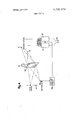
- FIG. 2 illustrates the diagram of a lock with a holographic key, which is an application of the identification system in accordance with the invention.
- This lock has a key 10 and a key seat 11 At one side of the plane of this seat there are arranged two light sources 6 and 7 and at the other side three photo-detectors 8, 9 and 13. The position of these sources and photo-detectors is defined with respect to the seat 11 in accordance with a predetermined code which means that to the source 6 there corresponds an image point at 8 and to the source 7 image points at 9 and 13.
- the light sources 6 and 7 are supplied through terminals 15 (connected for example to the mains) by a supply circuit 17 whose outputs and 171 respectively feed the sources 6 and 7 through the medium of respective circuits l8 and 19 for evaluating the supplied current or power, this depending upon the type of source used as will be explained in detail hereinafter.
- the circuit 17 also ensures the electrical supply to other parts of the lock (connections not shown).
- a contact-breaker controls a switch 16 which supplies the circuit 17, when a key 10 carrying a key hologram 1 is introduced into the key seat 11.
- the threshold level of the circuits 20, 21 and 22 is controlled respectively by signals coming from the circuits 18 and 19
- the logic circuit 23 comprises a first AND-circuit 230 connected to the threshold circuits 20 and 21 and a second AND-circuit 231, connected to the output of the first AND-circuit 230 and to the threshold circuit 22 and whose output is connected to the output 233 It is provided furthermore with an inverter circuit 232 connected to the output 233 its own output being connected to an alarm circuit 25 which can produce an alarm signal at the output 26.
- the circuit 25 also receives signals from a photo-detectors l4.
- the later will then supply a signal of an amplitude higher than the preset threshold of the circuit 20 the level of which is preset to a value which takes account of the normal light intensity of the source 6 and of the known efficiency of the key hologram, and varies an a function of the real luminous intensity supplied by the source 6 under the effect of the signals produced by the circuit 18 A signal will therefore be transmitted by the threshold circuit 20 to one of the inputs of the AND-circuit 230
- the key hologram 1 will produce two real images of the source 7 on the photo-detectors 9 and 13.
- the luminous intensity of the sources 6 and 7 can vary with time, for example as a consequence of variations in the mains voltage at the terminals or variations in the characteristics of the supply circuits. These variations in the luminous intensity of the sources 6 and 7 are translated into terms of proportional variations in the luminous intensities received respectively by the photo-detector 8 and the photodetectors 9 and 13 And the levels of the signals produced by these photo-detectors can drop to below the thresholds of the circuits or 21 and 22 which could inhibit the release of the lock even when the proper key is used.
- a feedback line is used which makes it possible to vary the thresholds of the circuits 20, and 21 and 22 as a function respectively of the luminous intensities produced by the sources 6 and 7
- the circuits l8 and 19 produce control signals, which cause the levels of the thresholds to vary around predetermined nominal values, for example as a function of the value of the supply current to the sources 6 and 7 if electroluminescent diodes are involved (in which case the luminous intensity emitted is substantially proportional to the current through the diode), or as a function of the square of the value of said current if electric bulbs are being used (the case which will be considered in more detail in the description of FIG. 5).
- the circuit 232 is a signal inverter and is well known per se. It is supplied with energy, once a key inserted in the key seat 11 has operated the contact-breaker 12 and it supplies a signal to the circuit 25 if it receives no signal from the circuit 231 the reverse being also true. Thus, if the circuit 232 supplies a signal to the circuit 25 this proves that a key, which is not the correct one, has been used in an attempt to release the lock, the circuit 25 then produces an alarm signal at the output 26 which signal can be employed to trigger any suitable alarm device or can be transmitted to a central supervisory panel.
- the photo-detector 14 can also trigger the circuit 25 if an incorrect key is used, under the effect of the diffused light which it receives in this case through the hologram, so that it duplicates the alarm circuit utilizing the circuit 232.
- variable thresholds of the circuits connected to the photo-detectors are controlled, in respect of each source, by a additional photo-detector.
- the key hologram MW produces an additional real image of the source 7 which image is formed on the photo-detector MP9.
- the signal furnished by the detector 109 controls a circuit H9 which generates signals which control the variable thresholds of the circuits 21 and 22 which are thus regulated as a function of the luminous intensity of the source 7 If the key hologram Wt) has been broken and if there remains only one or a few pieces of it left in position in the key It) it is merely necessary to close off the openings left in the key by the missing parts in order to prevent triggering of the alarm.
- the detector 109 will take into account the fact that the amount of light transmitted is lower than if the hologram had been whole, and will accordingly lower the thresholds of the circuits 21 and 22 thus enabling the lock to be opened.
- FIG. 5 there is shown a portion of a variant embodiment of the identification system in accordance with the invention.
- a key hologram operating by transmission has been employed.
- the same system is applicable to key holograms operating by reflection, these then producing real images which are situated at the same side as the light sources, in relation to the plane of the hologram.
- the key lltl has four key holograms lltlll, W2, W3 and llh ll operating by reflection, each corresponding to a given wavelength.
- FIG..6 illustrates a variant embodiment in which two keys are employed in series for releasing a lock.
- the first key 36 produces two real images 37 and 33 of the source 35, which act as light sources with respect to the key 39 the latter producing in turn images of these on the photo-detectors 40 and M and upon the photodetector 42.
- the system considered does not allow the use of a pass-key which is possible with conventional locks. However, it is nevertheless possible to conceive of a system of n locks which can all be opened by the same general key and each one separately by an individual key as well. For this purpose, it suffices that the pass key should carry the n key holograms corresponding to the n locks side-by-side in a predetermined order and to position in each individual key, the corresponding key hologram in the position so determined.
- a hologram identification system for identifying objects carrying at least one hologram key means storing a pattern of interference fringes constructed from light beams respectively emitted by m point reference sources and focused on n luminous object points; the locations of said point sources and said object points in relation to said hologram key means being characteristic of a predetermined correspondence code said identification system comprising: m point light sources and n point photo-detectors located in respective predetermined locations determined by said correspondence code, m and n being positive integers higher than one; means for positioning said hologram key means in a location where said hologram key means actually focuses said sources onto said photo-detectors logic circuit means connected to said photo-detectors and having an output for supplying a first control signal when, upon insertion of said hologram key means in said location, said n photo-detectors simultaneously supply respective signals and supply mans for supplying electrical energy to said sources and said logic circuit means.
- said logic circuit means comprise threshold circuits for said control signal to be supplied if said photo-detector signals have respective amplitudes simultaneously higher than respective predetermined thresholds.
- said logic circuit means comprise n variable threshold circuits connected respectively to said photo-detectors and having each a threshold level control input; m evaluating circuits, coupled respectively to said light sources and having outputs respectively connected to said control inputs of said threshold circuits which are connected to said photo-detectors corresponding re spectively to said sources, for evaluating the light intensities respectively supplied by said sources and for supplying threshold control signals; and coincidence circuit means having 11 inputs respectively connected to said threshold circuits and an output for supplying said first control signal.
- said inserting means comprise means for inserting a plurality of key holograms in series, at least the first of which operates by transmission, the real point images supplied by one of said holograms serving as point light sources for the next one of said holograms.
- said key hologram is an hologram operating by reflection
- said sources are white light sources
- said photodetectors are selected for being sensitive to the wavelengths of the light radiations reflected by said hologram.
- said evaluating circuits comprise each an auxiliary photodetector and said key hologram forms an extra real image of the corresponding light source on a predetermined location where said auxiliary photo-detector is located.
- said logic circuit means further comprise an alarm arrangement for signalling that the illumination of said photodetectors is different from the illumination according to said code.
- a system as claimed in claim 7 wherein said arrangement comprises an alarm circuit and an extra photo-detector connected to said alarm circuit.
Landscapes
- Physics & Mathematics (AREA)
- Engineering & Computer Science (AREA)
- General Physics & Mathematics (AREA)
- Multimedia (AREA)
- Theoretical Computer Science (AREA)
- Holo Graphy (AREA)
Applications Claiming Priority (1)
| Application Number | Priority Date | Filing Date | Title |
|---|---|---|---|
| FR6923274A FR2053562A5 (da) | 1969-07-09 | 1969-07-09 |
Publications (1)
| Publication Number | Publication Date |
|---|---|
| US3735374A true US3735374A (en) | 1973-05-22 |
Family
ID=9037183
Family Applications (1)
| Application Number | Title | Priority Date | Filing Date |
|---|---|---|---|
| US00049612A Expired - Lifetime US3735374A (en) | 1969-07-09 | 1970-06-25 | Hologram identification system |
Country Status (5)
| Country | Link |
|---|---|
| US (1) | US3735374A (da) |
| DE (1) | DE2033963A1 (da) |
| FR (1) | FR2053562A5 (da) |
| GB (1) | GB1310132A (da) |
| NL (1) | NL7010142A (da) |
Cited By (13)
| Publication number | Priority date | Publication date | Assignee | Title |
|---|---|---|---|---|
| US3940738A (en) * | 1974-07-10 | 1976-02-24 | Teeters Lloyd L | Electric lock |
| US4011435A (en) * | 1974-02-01 | 1977-03-08 | Ncr Corporation | Optical indicia marking and detection system |
| DE2546007A1 (de) * | 1975-10-14 | 1977-04-21 | Siemens Ag | Faelschungssichere ausweiskarte |
| US4084153A (en) * | 1976-03-15 | 1978-04-11 | Harris Corporation | Apparatus for reconstructing a binary bit pattern |
| US4094577A (en) * | 1971-04-13 | 1978-06-13 | Thomson-Csf | High-resolution, wide-field holographic lens |
| US4544266A (en) * | 1981-10-27 | 1985-10-01 | Lgz Landis & Gyr Zug Ag | Apparatus and a method for testing the authenticity of documents |
| US4641017A (en) * | 1983-12-15 | 1987-02-03 | Herman Lopata | Fraud resistant credit card system |
| US5078501A (en) * | 1986-10-17 | 1992-01-07 | E. I. Du Pont De Nemours And Company | Method and apparatus for optically evaluating the conformance of unknown objects to predetermined characteristics |
| US5159474A (en) * | 1986-10-17 | 1992-10-27 | E. I. Du Pont De Nemours And Company | Transform optical processing system |
| US5331443A (en) * | 1992-07-31 | 1994-07-19 | Crown Roll Leaf, Inc. | Laser engraved verification hologram and associated methods |
| US5442433A (en) * | 1989-08-11 | 1995-08-15 | Nhk Spring Co., Ltd. | Identification system for an article having individually attached patches |
| US20100085562A1 (en) * | 2008-10-08 | 2010-04-08 | International Business Machines Corporation | Prismatic Lock And Key Security |
| US11131121B2 (en) * | 2019-05-25 | 2021-09-28 | Konstantin KHLOPKOV | Highly secure optical key access control system |
Citations (10)
| Publication number | Priority date | Publication date | Assignee | Title |
|---|---|---|---|---|
| US2931916A (en) * | 1955-09-30 | 1960-04-05 | Rca Corp | Document transcriber |
| US3064519A (en) * | 1960-05-16 | 1962-11-20 | Ibm | Specimen identification apparatus and method |
| US3519322A (en) * | 1967-07-19 | 1970-07-07 | Trw Inc | Method for encoding and decoding information |
| US3532426A (en) * | 1967-11-08 | 1970-10-06 | Gen Electric | Holographic fingerprint identification |
| US3542448A (en) * | 1967-01-13 | 1970-11-24 | Ibm | Holographic recording and readout of digital information |
| US3543237A (en) * | 1966-07-29 | 1970-11-24 | Bell Telephone Labor Inc | Pattern recognition apparatus and method |
| US3553460A (en) * | 1968-06-12 | 1971-01-05 | Perkin Elmer Corp | Realization of combinatorial functions by utilizing optical holography and phase modulation by input information |
| US3599147A (en) * | 1967-09-12 | 1971-08-10 | Nat Res Dev | Character recognition systems and apparatus |
| US3600054A (en) * | 1965-08-13 | 1971-08-17 | Ibm | Holographic associative memory permitting conversion of a pattern to a machine-readable form |
| US3643216A (en) * | 1968-08-06 | 1972-02-15 | Rca Corp | Holographic identification system |
-
1969
- 1969-07-09 FR FR6923274A patent/FR2053562A5/fr not_active Expired
-
1970
- 1970-06-25 US US00049612A patent/US3735374A/en not_active Expired - Lifetime
- 1970-07-03 GB GB3248270A patent/GB1310132A/en not_active Expired
- 1970-07-08 DE DE19702033963 patent/DE2033963A1/de active Pending
- 1970-07-09 NL NL7010142A patent/NL7010142A/xx unknown
Patent Citations (10)
| Publication number | Priority date | Publication date | Assignee | Title |
|---|---|---|---|---|
| US2931916A (en) * | 1955-09-30 | 1960-04-05 | Rca Corp | Document transcriber |
| US3064519A (en) * | 1960-05-16 | 1962-11-20 | Ibm | Specimen identification apparatus and method |
| US3600054A (en) * | 1965-08-13 | 1971-08-17 | Ibm | Holographic associative memory permitting conversion of a pattern to a machine-readable form |
| US3543237A (en) * | 1966-07-29 | 1970-11-24 | Bell Telephone Labor Inc | Pattern recognition apparatus and method |
| US3542448A (en) * | 1967-01-13 | 1970-11-24 | Ibm | Holographic recording and readout of digital information |
| US3519322A (en) * | 1967-07-19 | 1970-07-07 | Trw Inc | Method for encoding and decoding information |
| US3599147A (en) * | 1967-09-12 | 1971-08-10 | Nat Res Dev | Character recognition systems and apparatus |
| US3532426A (en) * | 1967-11-08 | 1970-10-06 | Gen Electric | Holographic fingerprint identification |
| US3553460A (en) * | 1968-06-12 | 1971-01-05 | Perkin Elmer Corp | Realization of combinatorial functions by utilizing optical holography and phase modulation by input information |
| US3643216A (en) * | 1968-08-06 | 1972-02-15 | Rca Corp | Holographic identification system |
Cited By (15)
| Publication number | Priority date | Publication date | Assignee | Title |
|---|---|---|---|---|
| US4094577A (en) * | 1971-04-13 | 1978-06-13 | Thomson-Csf | High-resolution, wide-field holographic lens |
| US4011435A (en) * | 1974-02-01 | 1977-03-08 | Ncr Corporation | Optical indicia marking and detection system |
| US3940738A (en) * | 1974-07-10 | 1976-02-24 | Teeters Lloyd L | Electric lock |
| DE2546007A1 (de) * | 1975-10-14 | 1977-04-21 | Siemens Ag | Faelschungssichere ausweiskarte |
| US4084153A (en) * | 1976-03-15 | 1978-04-11 | Harris Corporation | Apparatus for reconstructing a binary bit pattern |
| US4544266A (en) * | 1981-10-27 | 1985-10-01 | Lgz Landis & Gyr Zug Ag | Apparatus and a method for testing the authenticity of documents |
| US4641017A (en) * | 1983-12-15 | 1987-02-03 | Herman Lopata | Fraud resistant credit card system |
| US5078501A (en) * | 1986-10-17 | 1992-01-07 | E. I. Du Pont De Nemours And Company | Method and apparatus for optically evaluating the conformance of unknown objects to predetermined characteristics |
| US5159474A (en) * | 1986-10-17 | 1992-10-27 | E. I. Du Pont De Nemours And Company | Transform optical processing system |
| US5442433A (en) * | 1989-08-11 | 1995-08-15 | Nhk Spring Co., Ltd. | Identification system for an article having individually attached patches |
| US5331443A (en) * | 1992-07-31 | 1994-07-19 | Crown Roll Leaf, Inc. | Laser engraved verification hologram and associated methods |
| US20100085562A1 (en) * | 2008-10-08 | 2010-04-08 | International Business Machines Corporation | Prismatic Lock And Key Security |
| US8462322B2 (en) | 2008-10-08 | 2013-06-11 | International Business Machines Corporation | Prismatic lock and key security |
| US9274508B2 (en) | 2008-10-08 | 2016-03-01 | Lenovo Enterprise Solutions (Singapore) Pte. Ltd. | Prismatic lock and key security |
| US11131121B2 (en) * | 2019-05-25 | 2021-09-28 | Konstantin KHLOPKOV | Highly secure optical key access control system |
Also Published As
| Publication number | Publication date |
|---|---|
| GB1310132A (en) | 1973-03-14 |
| NL7010142A (da) | 1971-01-12 |
| DE2033963A1 (de) | 1971-01-28 |
| FR2053562A5 (da) | 1971-04-16 |
Similar Documents
| Publication | Publication Date | Title |
|---|---|---|
| US3735374A (en) | Hologram identification system | |
| US4129382A (en) | Method and apparatus for storing and reading authenticating information | |
| US4645936A (en) | Multi-denomination currency validator employing a plural selectively-patterned reticle | |
| US4881268A (en) | Paper money discriminator | |
| US4400616A (en) | Document card containing information in holographic form | |
| CN101038689B (zh) | 图像读取装置和纸币读取方法 | |
| US3688269A (en) | Electronic key lock having data coded key | |
| US3769515A (en) | Electro-optical lock and method | |
| KR100274406B1 (ko) | 유가증권 식별장치 및 방법 | |
| US3542448A (en) | Holographic recording and readout of digital information | |
| US4405858A (en) | Light gate with controlled optical couplers | |
| US3609713A (en) | Data entry means | |
| ES2055793T3 (es) | Metodo para discriminar la autenticidad de un billete y un aparato para ello. | |
| US3776616A (en) | Coherent optical multichannel correlator | |
| US5341029A (en) | Method for supervising a switch | |
| US2953689A (en) | Actuating system | |
| US3769514A (en) | Coded radiation reflective lock | |
| GB1100820A (en) | Improvements in or relating to data processing arrangements | |
| US3750150A (en) | Photoelectric keyboard for data input devices or the like | |
| US3180491A (en) | Currency detectors | |
| GB1419134A (en) | Device for identification of pattern by use of coherent light | |
| US5377807A (en) | Coin validator with optical coupling | |
| US3792469A (en) | Multiplexed alarm transmission system having alarm storage circuits | |
| RU2085689C1 (ru) | Кодовое устройство | |
| US3457424A (en) | Perforated record system using light transmitting block |