US3699451A - Antenna selection and impedance matching apparatus - Google Patents
Antenna selection and impedance matching apparatus Download PDFInfo
- Publication number
- US3699451A US3699451A US774394A US3699451DA US3699451A US 3699451 A US3699451 A US 3699451A US 774394 A US774394 A US 774394A US 3699451D A US3699451D A US 3699451DA US 3699451 A US3699451 A US 3699451A
- Authority
- US
- United States
- Prior art keywords
- pushbutton
- converters
- switch
- converter
- cranks
- Prior art date
- Legal status (The legal status is an assumption and is not a legal conclusion. Google has not performed a legal analysis and makes no representation as to the accuracy of the status listed.)
- Expired - Lifetime
Links
Images


Classifications
-
- H—ELECTRICITY
- H03—ELECTRONIC CIRCUITRY
- H03J—TUNING RESONANT CIRCUITS; SELECTING RESONANT CIRCUITS
- H03J1/00—Details of adjusting, driving, indicating, or mechanical control arrangements for resonant circuits in general
- H03J1/06—Driving or adjusting arrangements; combined with other driving or adjusting arrangements, e.g. of gain control
- H03J1/08—Toothed-gear drive; Worm drive
-
- H—ELECTRICITY
- H03—ELECTRONIC CIRCUITRY
- H03J—TUNING RESONANT CIRCUITS; SELECTING RESONANT CIRCUITS
- H03J5/00—Discontinuous tuning; Selecting predetermined frequencies; Selecting frequency bands with or without continuous tuning in one or more of the bands, e.g. push-button tuning, turret tuner
- H03J5/02—Discontinuous tuning; Selecting predetermined frequencies; Selecting frequency bands with or without continuous tuning in one or more of the bands, e.g. push-button tuning, turret tuner with variable tuning element having a number of predetermined settings and adjustable to a desired one of these settings
- H03J5/04—Discontinuous tuning; Selecting predetermined frequencies; Selecting frequency bands with or without continuous tuning in one or more of the bands, e.g. push-button tuning, turret tuner with variable tuning element having a number of predetermined settings and adjustable to a desired one of these settings operated by hand
- H03J5/12—Settings determined by a number of separately-actuated driving means which adjust the tuning element directly to desired settings
Definitions
- a switch for switching in selectively one of a plurality of antennae a variable element for the impedance matching of an antenna circuit including a feeder, a switch for switching in selectively one of a plurality of converters, and a variable element for the tuning of a particular converter, all of which are arranged to be moved with their respective cranks.
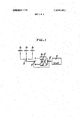
- FIG. 1 is a diagram of an electric circuit in accordance with the invention
- FIG. 2 is a top plan view of a pushbutton-type tuning apparatus, with a central portion omitted, according to the invention
- FIG. 3 is a top plan view, member used therein;
- FIG. 4 is a front view of a setting plate used in the tuning member of FIG. 3;
- FIG. 5 is a construction diagram of a variable element used in the apparatus of the invention.
- FIG. 6 is an operation mechanism diagram of a changeover switch employed in accordance with the invention.
- FIG. 7 is a side view of the tuning member of FIG. 3; and I FIG. 8 is a top plan view of the tuner of FIG. 3 with the setting plates locked in position.
- This invention relates to a tuning apparatus with which selection can be made of a plurality of antennae provided for a television receiver or the like whereby electric waves coming to a selected antenna may be selected according to respective bands and any desired frequency in a band can be freely selected. Additionally, this invention is directed to a tuning apparatus by which tuning can be effected by a single operation and impedance matching between an antenna circuit including a feeder and a receiving input circuit can be effected at the time of tuning.
- a selecting circuit when a plurality of antennae are provided for a single receiver and these antennae are selectively used, a selecting circuit must be constructed with due regard to the product of the number of antennae and the number of bands. Such a circuit becomes very complicated. Additionally, if a selecting operation thereof is effected at each time of tuning, the operation requires skill and is liable to be lacking in practicability.
- An object of the invention is to provide that the construction of the selecting circuit may be simplified, and that antenna switching, band switching and frequency tuning can be effected by a single operation and, in addition, that the input signal can be transmitted most rationally.
- FIG. 1 shows an electric circuit according to the invention.
- a A, and A are antennae corresponding to broadcasting stations differing in direction.
- S is a switch for selectively utilizing these antennae.
- C is a variable partly in section, of a tuning impeder such as a variable condensor connected to the switchS for impedance matching to an antenna circuit including a feeder.
- B and B are converters, each of which comprises an RF amplifier circuit, a local-oscillator circuit and a frequency-converter circuit, for respective bands such as VHF. UHF, etc., impedance matching being provided by the variable condensor C;
- S is a change-over switch connected between the converters B and B and the subsequent IF amplifier circuit D. Switch S is arranged to move with the rotatable shaft of the variable condensor C, as will be shown.
- variable condensor C The construction of the variable condensor C is shown in FIG. 5.
- a movable electrode C is mounted on a movable shaft X and a pair of stationary electrodes C,
- the change-over switch S is arranged to be operated by a cam E mounted on the shaft X of the variable condensor C. It is so operated by the cam E that, when the movable electrode C is rotated in the direction of stationary electrode C the switch S closes the circuit S, on the side of the converter B and, when the movable electrode C is rotated in the direction of the other stationary electrode C the circuit S on the side of the other converter B is closed.
- F F and F are cranks rotatably mounted on a frame G. These cranks have individual rotating adjustment mechanisms H H and H I is a tuning member having a setting plate for setting the rotation of the corresponding cranks. A plurality of tuning members corresponding to the number of tuning frequencies are mounted slidably on the frame G.
- variable condensor C and the change-over switch S are arranged to move individually with respective of the cranks F F and F
- a variable element C' C,' and C for tuning in the converter circuits
- each element C, and C preferably comprising an element for the RF amplifier circuit and an element for the local-oscillator circuit
- the switch S for antenna switching (as shown in FIG. 1) are arranged to move individually with respective of the cranks F F and F
- Element 1 is an arm whose frontend is in engagement with a supporting rod 2 projecting from the rear plate g of the frame. The rear end of the arm is in engagement with a groove or slot in the front plate 3'.
- This arm 1 is provided with a segment or semi-circular setting plate 4 rotatably attached thereto by a pin 3, a locking member 5 for locking the plate 4 in position, a wedge-shaped member 6 longitudinally slidable within a channel-shaped portion 1a provided on the arm 1 to actuate the locking member 5, and another segment or semi-circular setting plate 8 rotatably attached thereto by a pin 7 at a position spaced from the above-mentioned setting plate 4.
- Setting plate 8 has in its peripheral edge portion several slits 9 as shown in FIG.
- Element is an arm which forms a pair together with the arm 1 mentioned above. The front end thereof is in engagement with the supporting rod 2 and the rear end thereof has an inwardly bent engaging member 1 1.
- This arm 10 is connected through a pin 12 projecting from the wedge-shaped member 6 to the arm 1 and this pin 12 is slidable within a slot 13 in the arm 1. Additionally, this arm 10 has a tongue 14 engageable and disengageable with each of the slits 9 of the setting plate 8. This tongue 14 projects through a slot 15 in the arm 1.
- a first member 1 there is formed a first member 1,.
- Element 16 is an arm interposed between the first member I, and the second member I,, and the arm 16 is provided at its rear end with a pushbutton 18 having its front surface 17 formed as an are, a tiltable supplementary plate 19 which is to contact the rear end surfaces of the arms 10 and 10 while being pushed by the front surface 17, and an engaging opening 20 in engagement with both the engaging members 11 and 11', thus there being formed a third member 1,.
- These three members I,, I, and 1, constitute a single tuning member I, and those members are independently slidably mounted on the frame G, and the third member I, is tiltable at its engaging portion with the supporting rod 2.
- Elements 21 and resilient plate 5 keep the third member I between the first and second members I, and 1,.
- Elements 22 and 23 are return springs for the first and second members I, and I
- Elements 24 and 25 are stops for the first and second members I, and 1,.
- Each of the rotating adjustment mechanisms H, and H in FIG. 2 is so constructed that when a knob 26 is pushed against a spring 27, a bevel gear 29 provided at the end of a shaft 28 meshes with a bevel gear 30 provided on the crank side and, when the knob 26 is released, the shaft 28 returns under the action of the spring 27.
- the rotating adjustment mechanism H is so constructed that, upon rotation of a knob 31, a crown gear 34 meshes with a pinion 33 provided at the end of a shaft 32 and is rotated. This rotation is transmitted to the crank F, through a clutch portion 35. The clutch portion 35 is released through a lever rod 36 when the tuning member I is pushed.
- the rotating adjustment mechanisms are different in construction as described above so that the rotating adjustment mechanism H, has more precision in comparison with the other rotating adjustment mechanisms H, and H, so that the rotating angle of the crank F, can be adjusted precisely.
- the rotating angles of the cranks F,, F, and F are first adjusted for selection of a particular broadcasting station through respective rotating adjustment mechanisms H,, H, and H
- the crank F is rotated through the mechanism H, so that the switch S (for example, a rotary switch) may be operated for selecting a particular antenna.
- the crank F is rotated by the mechanism H, so that the variable condensor C and the switch 8' are adjusted for selecting a particular converter and, at the same time, for obtaining by the variable condensor an impedance matching between the input circuit of the selected converter and the selected antenna circuit including its feeder.
- the crank F is rotated by the mechanism H, to that the condensor C is adjusted for tuning in a predetermined broadcast frequency.
- the members 1,, I, and I are concomitantly advanced and their respective setting plates 4, 4 and 8 collide'with their corresponding cranks F,, F, and F, to follow the same until their advance is stopped. If then the pushbutton 18 is pushed further with force, the arms l6, l0 and 10' are advanced and in accordance therewith the wedge-shaped members 6 and 6 actuate the locking members 5 and 5' for locking the setting plates 4 and 4' on the arms 1 and 1, and at the same time the tongue 14 is inserted in one of the slits 9 of the setting plate 8 for locking this plate. If, at this point, the pushing force on the pushbutton 18 is released, the members I,, I, and I, are returned by the return springs 22 and 23 to their positions as shown in solid lines in FIG. 3.
- the tuning member I memorizes all the information necessary for tuning. If, accordingly, each tuning member is set to memorize all factors corresponding to its respective tuning frequency, then'any desired frequency can be easily selected by a single operation by simple pushing the corresponding tuning member from the position shown by solid lines in FIG. 3.
- the setting plates 4, 4', 8 each is in its free condition and is separated with a certain spacing from the corresponding cranks F F,, F,. From this condition, the cranks F,, F,, F, are set at certain angles of rotation by adjustment of the respective rotating adjustment mechanisms H,, H H Then the pushbutton 18 is pushed in the direction of the arrow whereby in a first step the arms 1, 10, 1', 10', 16 are advanced together and the setting plates 4, 4', 8 are rotated to the angles of the corresponding cranks F,, F F,.
- the arms 1, l' are stopped in advance and only the arms 10, 10', 16 are advanced, whereby the wedge-shaped member 6 enters between the locking member 5' and the arm 1', and the tongue 14 enters the selected groove 9 of the setting plate 8, and thus the setting plates 4, 4', 8 are locked and memorize the rotating angles of the corresponding rotating cranks F,, F F
- the pushbutton 18 is released the arms are returned by the action of the springs 22, 23 to the position where the stops 24, 25 strike against the machine frame g and the condition shown in dotted lines in FIG. 3 is assumed. If, from this condition, the pushbutton 18 is pushed in the arrow direction, the setting plates 4, 4, 8 strike against the corresponding cranks F,, F F and the rotating angles memorized by the setting plates are imposed on the cranks.
- any one of the antennas is selected through the switch S. If the rotating adjustment mechanism H, is operated, the capacitance of the variable impeder C is changed to select the convertor and at the same time the switch S' is changed to connect the selected convertor to the IF amplifier circuit D. If the rotating adjustment mechanism H, is operated the variable impeder C of the convertor is changed.
- a switch for antenna switching and a variable element for impedance matching of an antenna circuit including a feeder are connected between a plurality of antennae and converters, and a change-over switch movable with the variable element for impedance matching for selecting a particular converter is connected between the converters and the following circuit, as described above, so that the circuit construction for switching of the antennae and the converters is extremely simplified and an input signal obtained by an antenna can be effectively transmitted to the receiver.
- Apparatus for use in selectively coupling one of a plurality of antennas to a signal receiving circuit via one of a plurality of selectively operable converters, each converter being adjustable to a particular broadcast frequency
- said apparatus comprising first switch means for selectively coupling one of said antennas to said converters, second switch means for selectively coupling one of said converters to the selected antenna and the signal receiving circuit, a variable impedor connected in series with the first switch means for matching the impedance of the selected antenna to that of the selected converter, third means for coupling the variable impedor and the second switch means for simultaneous operation to provide impedance matching for the selected converter, fourth means for adjusting each converter to a particular broadcast frequency, tuning means selectively connectable with said first, second and fourth means to individually preset the same for the particular broadcast frequency and correlate a selected antenna and a selected associated converter while adjusting said converter to a pre-determined value, and pushbutton means for operating said first, second and fourth means after the latter have been pre-set by the tuning means and disconnected therefrom.
- a pushbutton type tuner in combination with a circuit including a plurality of antennas, a plurality of converters, a first switch connected between said antennas and said converters for selecting one of said antennas for connection with the converters, a variable impedor connected in series with the switch for impedance matching with the converters, a single IF circuit, a second switch connected between the converters and the IF circuit for connecting a selected converter to said circuit, said tuner comprising a first crank connected to said first switch, a second crank connected to both the variable impedor and thesecond switch, independent rotating adjustment mechanisms respectively coupled to said cranks to preset the positions thereof to a selected antenna and converter for a particular broadcast frequency, and a tuning means for memorizing the pre-set positions of the cranks and for reproducing same to bring the switches and impeder to said preset positions.
- a pushbutton type tuner as claimed in claim 2 comprising a third crank and independent rotating adjustment mechanism coupled thereto to pre-set the position of the third crank, each of the converters including a variable impedor, said tuning means being coupled to the third crank to memorize the pre-set position thereof and to reproduce the same to bring the rotating adjustment mechanism to said pre-determined position.
- a pushbutton type tuner as claimed in claim 3, comprising a pushbutton to operate said cranks, said tuning means including three setting plates for memorizing rotation angles of the three cranks, means to lock these plates when the pushbutton is pushed and to release the plates when the pushbutton is pulled.
- a pushbutton apparatus as claimed in claim 4 wherein said tuning means comprises three members the first member being provided with two setting plates and the second member being provided with the pushbutton.
- a pushbutton apparatus as claimed in claim 5 wherein the third member is mounted between the first and second members, and is arranged so that when the pushbutton is pushed or pulled either the setting plate on the first member or the setting plate on the second member may be locked or unlocked.
Landscapes
- Channel Selection Circuits, Automatic Tuning Circuits (AREA)
- Variable-Direction Aerials And Aerial Arrays (AREA)
Abstract
On a frame having three cranks independently adjustable by rotation, there are slidably mounted tuning members each having three setting plates corresponding to the three cranks and capable of being locked and released by a single pushbutton operation. Furthermore, there are provided a switch for switching in selectively one of a plurality of antennae, a variable element for the impedance matching of an antenna circuit including a feeder, a switch for switching in selectively one of a plurality of converters, and a variable element for the tuning of a particular converter, all of which are arranged to be moved with their respective cranks. As a result, antenna switching and band switching and frequency selection can be effected simultaneously by a single operation.
Description
United States Patent Ohaski ['54] ANTENNA SELECTION AND IMPEDANCE MATCHING APPARATUS 72 Inventor: Tamaki Ohaski, 162 9 Tanashi-shi,
Tokyo, Japan [22] Filed: Nov. 8, 1968 [21] Appl. No.: 774,394
[30] Foreign Application Priority Data Nov. 1,], 1967 Japan ..42/72253 [52] US. Cl. ..325/368, 325/370, 325/381, 325/387, 325/458 [51] Int. Cl. ..H04b 1/18 [58] Field of Search ..325/366, 268, 372, 370, 373, 325/381, 374, 378 334/7, 52, 55; 74/1033;
' [56] References Cited UNITED STATES PATENTS 2,179,298 11/1939 Mauke ..325/372 X 2,815,442 12/1957 Davis ..325/370 [4 1 Oct. 17, 1972 Attorney-Waters, Roditi, Schwartz & Nissen [57] ABSTRACT I On a frame having three cranks independently adjustable by rotation, there are slidably mounted tuning members each having three setting platescorresponding to the three cranks and capable of being locked and released by a single pushbutton operation. Furthermore, there are provided a switch for switching in selectively one of a plurality of antennae, a variable element for the impedance matching of an antenna circuit including a feeder, a switch for switching in selectively one of a plurality of converters, and a variable element for the tuning of a particular converter, all of which are arranged to be moved with their respective cranks. As a result, antenna switching and band switching and frequency selection can be effected simultaneously by a single operation.
6 Claims, 8 Drawing Figures LE AMP a PA'TE'NTEnnm 11 m2 3.699.451-
' sum 2 or 4 \NVENTOR ATTORNEY PATENTEDncT n ma 3.699.451
INVENTOR ATTORNEY ANTENNA SELECTION AND IMPEDANCE MATCHING APPARATUS DRAWING FIG. 1 is a diagram of an electric circuit in accordance with the invention;
FIG. 2 is a top plan view of a pushbutton-type tuning apparatus, with a central portion omitted, according to the invention;
. FIG. 3 is a top plan view, member used therein;
FIG. 4 is a front view of a setting plate used in the tuning member of FIG. 3;
FIG. 5 is a construction diagram of a variable element used in the apparatus of the invention;
FIG. 6 is an operation mechanism diagram of a changeover switch employed in accordance with the invention;
FIG. 7 is a side view of the tuning member of FIG. 3; and I FIG. 8 is a top plan view of the tuner of FIG. 3 with the setting plates locked in position.
DETAILED EXPLANATION OF THE INVENTION This invention relates to a tuning apparatus with which selection can be made of a plurality of antennae provided for a television receiver or the like whereby electric waves coming to a selected antenna may be selected according to respective bands and any desired frequency in a band can be freely selected. Additionally, this invention is directed to a tuning apparatus by which tuning can be effected by a single operation and impedance matching between an antenna circuit including a feeder and a receiving input circuit can be effected at the time of tuning.
It is well known that UHF is currently being used as a broadcast frequency for television and television receivers for both VHF and UHF are required. For these kinds of very high frequencies, however, it is difficult for a single antenna to receive various broadcast frequencies coming from various broadcasting stations efficiently, due to directivity and other problems. Accordingly, it is necessary for a single television receiver to provide a number of antennae which are different from each other with respect to incoming electric-wave direction.
However, when a plurality of antennae are provided for a single receiver and these antennae are selectively used, a selecting circuit must be constructed with due regard to the product of the number of antennae and the number of bands. Such a circuit becomes very complicated. Additionally, if a selecting operation thereof is effected at each time of tuning, the operation requires skill and is liable to be lacking in practicability.
An object of the invention is to provide that the construction of the selecting circuit may be simplified, and that antenna switching, band switching and frequency tuning can be effected by a single operation and, in addition, that the input signal can be transmitted most rationally.
The invention will next be explained in detail with reference to the accompanying drawings.
FIG. 1 shows an electric circuit according to the invention. A A, and A, are antennae corresponding to broadcasting stations differing in direction. S is a switch for selectively utilizing these antennae. C is a variable partly in section, of a tuning impeder such as a variable condensor connected to the switchS for impedance matching to an antenna circuit including a feeder. B and B are converters, each of which comprises an RF amplifier circuit, a local-oscillator circuit and a frequency-converter circuit, for respective bands such as VHF. UHF, etc., impedance matching being provided by the variable condensor C; S is a change-over switch connected between the converters B and B and the subsequent IF amplifier circuit D. Switch S is arranged to move with the rotatable shaft of the variable condensor C, as will be shown.
The construction of the variable condensor C is shown in FIG. 5. A movable electrode C is mounted on a movable shaft X and a pair of stationary electrodes C,
and C are disposed to the right and left of the movable electrode C When the shaft X is rotated to the position where the movable electrode C faces the stationary electrode C, on one side, there is formed a variable condensor for the impedance matching of the converter B on one side, and when the movable electrode C faces the stationary electrode C; on the other side, there is formed a variable condensor for impedance matching of the converter B on the other side.
As shown in FIG. 6, the change-over switch S is arranged to be operated by a cam E mounted on the shaft X of the variable condensor C. It is so operated by the cam E that, when the movable electrode C is rotated in the direction of stationary electrode C the switch S closes the circuit S, on the side of the converter B and, when the movable electrode C is rotated in the direction of the other stationary electrode C the circuit S on the side of the other converter B is closed.
The pushbutton-type tuning apparatus of the invention will next be explained in detail as follows:
F F and F (FIG. 2) are cranks rotatably mounted on a frame G. These cranks have individual rotating adjustment mechanisms H H and H I is a tuning member having a setting plate for setting the rotation of the corresponding cranks. A plurality of tuning members corresponding to the number of tuning frequencies are mounted slidably on the frame G.
The variable condensor C and the change-over switch S, a variable element C' (C,' and C for tuning in the converter circuits (each element C, and C, preferably comprising an element for the RF amplifier circuit and an element for the local-oscillator circuit), and the switch S for antenna switching (as shown in FIG. 1) are arranged to move individually with respective of the cranks F F and F Next the construction of the tuning member I will be explained in detail with reference to FIG. 3.
4. Element is an arm which forms a pair together with the arm 1 mentioned above. The front end thereof is in engagement with the supporting rod 2 and the rear end thereof has an inwardly bent engaging member 1 1. This arm 10 is connected through a pin 12 projecting from the wedge-shaped member 6 to the arm 1 and this pin 12 is slidable within a slot 13 in the arm 1. Additionally, this arm 10 has a tongue 14 engageable and disengageable with each of the slits 9 of the setting plate 8. This tongue 14 projects through a slot 15 in the arm 1. Thus, there is formed a first member 1,. I, is a second member which is equivalent in construction to the first member 1, except that the setting plate 8 and the tongue 14 are omitted and in that the position of the setting plate 4' in relation to plate 4 of the arm 1 is different. In the drawing the second member I, is distinguished from the first member I, in that corresponding reference numerals are primed. Element 16 is an arm interposed between the first member I, and the second member I,, and the arm 16 is provided at its rear end with a pushbutton 18 having its front surface 17 formed as an are, a tiltable supplementary plate 19 which is to contact the rear end surfaces of the arms 10 and 10 while being pushed by the front surface 17, and an engaging opening 20 in engagement with both the engaging members 11 and 11', thus there being formed a third member 1,. These three members I,, I, and 1,, constitute a single tuning member I, and those members are independently slidably mounted on the frame G, and the third member I, is tiltable at its engaging portion with the supporting rod 2.
Elements 21 and resilient plate 5 keep the third member I between the first and second members I, and 1,. Elements 22 and 23 are return springs for the first and second members I, and I Elements 24 and 25 are stops for the first and second members I, and 1,.
Each of the rotating adjustment mechanisms H, and H in FIG. 2 is so constructed that when a knob 26 is pushed against a spring 27, a bevel gear 29 provided at the end of a shaft 28 meshes with a bevel gear 30 provided on the crank side and, when the knob 26 is released, the shaft 28 returns under the action of the spring 27. The rotating adjustment mechanism H, is so constructed that, upon rotation of a knob 31, a crown gear 34 meshes with a pinion 33 provided at the end of a shaft 32 and is rotated. This rotation is transmitted to the crank F, through a clutch portion 35. The clutch portion 35 is released through a lever rod 36 when the tuning member I is pushed. The rotating adjustment mechanisms are different in construction as described above so that the rotating adjustment mechanism H, has more precision in comparison with the other rotating adjustment mechanisms H, and H, so that the rotating angle of the crank F, can be adjusted precisely.
In operation, the rotating angles of the cranks F,, F, and F are first adjusted for selection of a particular broadcasting station through respective rotating adjustment mechanisms H,, H, and H The crank F is rotated through the mechanism H, so that the switch S (for example, a rotary switch) may be operated for selecting a particular antenna. The crank F, is rotated by the mechanism H, so that the variable condensor C and the switch 8' are adjusted for selecting a particular converter and, at the same time, for obtaining by the variable condensor an impedance matching between the input circuit of the selected converter and the selected antenna circuit including its feeder. The crank F is rotated by the mechanism H, to that the condensor C is adjusted for tuning in a predetermined broadcast frequency.
If then the pushbutton 18 is pushed in the direction of the arrow, the members 1,, I, and I, are concomitantly advanced and their respective setting plates 4, 4 and 8 collide'with their corresponding cranks F,, F, and F, to follow the same until their advance is stopped. If then the pushbutton 18 is pushed further with force, the arms l6, l0 and 10' are advanced and in accordance therewith the wedge-shaped members 6 and 6 actuate the locking members 5 and 5' for locking the setting plates 4 and 4' on the arms 1 and 1, and at the same time the tongue 14 is inserted in one of the slits 9 of the setting plate 8 for locking this plate. If, at this point, the pushing force on the pushbutton 18 is released, the members I,, I, and I, are returned by the return springs 22 and 23 to their positions as shown in solid lines in FIG. 3.
Thus, the tuning member I memorizes all the information necessary for tuning. If, accordingly, each tuning member is set to memorize all factors corresponding to its respective tuning frequency, then'any desired frequency can be easily selected by a single operation by simple pushing the corresponding tuning member from the position shown by solid lines in FIG. 3.
As seen in FIG. 7, the setting plates 4, 4', 8 each is in its free condition and is separated with a certain spacing from the corresponding cranks F F,, F,. From this condition, the cranks F,, F,, F, are set at certain angles of rotation by adjustment of the respective rotating adjustment mechanisms H,, H H Then the pushbutton 18 is pushed in the direction of the arrow whereby in a first step the arms 1, 10, 1', 10', 16 are advanced together and the setting plates 4, 4', 8 are rotated to the angles of the corresponding cranks F,, F F,. If the pushbutton 18 is pushed further, the arms 1, l' are stopped in advance and only the arms 10, 10', 16 are advanced, whereby the wedge-shaped member 6 enters between the locking member 5' and the arm 1', and the tongue 14 enters the selected groove 9 of the setting plate 8, and thus the setting plates 4, 4', 8 are locked and memorize the rotating angles of the corresponding rotating cranks F,, F F If, then, the pushbutton 18 is released the arms are returned by the action of the springs 22, 23 to the position where the stops 24, 25 strike against the machine frame g and the condition shown in dotted lines in FIG. 3 is assumed. If, from this condition, the pushbutton 18 is pushed in the arrow direction, the setting plates 4, 4, 8 strike against the corresponding cranks F,, F F and the rotating angles memorized by the setting plates are imposed on the cranks.
If the rotating adjustment mechanism H, is operated, any one of the antennas is selected through the switch S. If the rotating adjustment mechanism H, is operated, the capacitance of the variable impeder C is changed to select the convertor and at the same time the switch S' is changed to connect the selected convertor to the IF amplifier circuit D. If the rotating adjustment mechanism H, is operated the variable impeder C of the convertor is changed.
If the pushbutton is pulled from the position shown by solid lines in FIG. 3 opposite to the direction of the arrow, all the setting plates 4, 4' and 8 will be released from their locking positions simultaneously. If it is desired to cause a tuning member to memorize another frequency of the same antenna and the same band, the pushbutton 18 is pulled while being inclined to the side of the second member 1 whereby the setting plate 4' alone is released from looking independently of the first member 1,. Accordingly, thereafter an adjustment only in the relation between the setting plate 4' and the crank F is needed.
it is well known that, in a television receiver or the like, it is required to transmit an input signal obtained by an antenna to the receiver at the highest possible efficiency and that an antenna circuit including a feeder and a receiver input circuit must be fully matched in impedance for removing any reflection at the connecting point. In conventional television (and similarly in a radio receiver), however, impedance matching within the receiver is usually provided on the basis of an antenna constant standardized on the manufacturing of the receiver. lf consideration is taken in an individual receiver because of the fact that the antenna constant is different depending on attaching manner, kinds, receiving frequencies or other conditions of the antenna, insufficiency in impedance matching cannot be avoided. This causes double images due to the reflecting phenomenon at the connecting point. There also exists the defect in color television that reappearance of color becomes difficult.
According to this invention, however, a switch for antenna switching and a variable element for impedance matching of an antenna circuit including a feeder are connected between a plurality of antennae and converters, and a change-over switch movable with the variable element for impedance matching for selecting a particular converter is connected between the converters and the following circuit, as described above, so that the circuit construction for switching of the antennae and the converters is extremely simplified and an input signal obtained by an antenna can be effectively transmitted to the receiver.
What is claimed is:
1. Apparatus for use in selectively coupling one of a plurality of antennas to a signal receiving circuit via one of a plurality of selectively operable converters, each converter being adjustable to a particular broadcast frequency, said apparatus comprising first switch means for selectively coupling one of said antennas to said converters, second switch means for selectively coupling one of said converters to the selected antenna and the signal receiving circuit, a variable impedor connected in series with the first switch means for matching the impedance of the selected antenna to that of the selected converter, third means for coupling the variable impedor and the second switch means for simultaneous operation to provide impedance matching for the selected converter, fourth means for adjusting each converter to a particular broadcast frequency, tuning means selectively connectable with said first, second and fourth means to individually preset the same for the particular broadcast frequency and correlate a selected antenna and a selected associated converter while adjusting said converter to a pre-determined value, and pushbutton means for operating said first, second and fourth means after the latter have been pre-set by the tuning means and disconnected therefrom.
2. A pushbutton type tuner in combination with a circuit including a plurality of antennas, a plurality of converters, a first switch connected between said antennas and said converters for selecting one of said antennas for connection with the converters, a variable impedor connected in series with the switch for impedance matching with the converters, a single IF circuit, a second switch connected between the converters and the IF circuit for connecting a selected converter to said circuit, said tuner comprising a first crank connected to said first switch, a second crank connected to both the variable impedor and thesecond switch, independent rotating adjustment mechanisms respectively coupled to said cranks to preset the positions thereof to a selected antenna and converter for a particular broadcast frequency, and a tuning means for memorizing the pre-set positions of the cranks and for reproducing same to bring the switches and impeder to said preset positions.
3. A pushbutton type tuner as claimed in claim 2 comprising a third crank and independent rotating adjustment mechanism coupled thereto to pre-set the position of the third crank, each of the converters including a variable impedor, said tuning means being coupled to the third crank to memorize the pre-set position thereof and to reproduce the same to bring the rotating adjustment mechanism to said pre-determined position. i
4. A pushbutton type tuner as claimed in claim 3, comprising a pushbutton to operate said cranks, said tuning means including three setting plates for memorizing rotation angles of the three cranks, means to lock these plates when the pushbutton is pushed and to release the plates when the pushbutton is pulled.
5. A pushbutton apparatus as claimed in claim 4 wherein said tuning means comprises three members the first member being provided with two setting plates and the second member being provided with the pushbutton.
6. A pushbutton apparatus as claimed in claim 5 wherein the third member is mounted between the first and second members, and is arranged so that when the pushbutton is pushed or pulled either the setting plate on the first member or the setting plate on the second member may be locked or unlocked.
UNITED STATES PATENT OFFICE (TER'IIFICAIIC ()F (IORREC'IION Patent NO; 3,699,451 V .Dated October 17, 1972' Inventor(s) Y'Iamaki Ohashi It is certified that error appears in the above-identified patent and that said Letters Patent are hereby corrected as shown below:
On 'the cover sheet [72] "Oha ski" should read Ohashi Also on the cover sheet [30] "42/72253" should read r- 67/72253 Signed and sealed-this 1st day of May 1973.
(SEAL) Attest:
EDWARD M.FLETCHER,JR. ROBERT GOTTSCHALK Attesting Officer Commissioner of Patents CBM PO-O50a10-E9 USCOMM-DC 6O376-P69 U.S. GOVERNMENT PRINTING OFFICE 1 I969 0-366- 34,
Claims (6)
1. Apparatus for use in selectively coupling one of a plurality of antennas to a signal receiving circuit via one of a plurality of selectively operable converters, each converter being adjustable to a particular broadcast frequency, said apparatus comprising first switch means for selectively coupling one of said antennas to said converters, second switch means for selectively coupling one of said converters to the selected antenna and the signal receiving circuit, a variable impedor connected in series with the first switch means for matching the impedance of the selected antenna to that of the selected converter, third means for coupling the variable impedor and the second switch means for simultaneous operation to provide impedance matching for the selected converter, fourth means for adjusting each converter to a particular broadcast frequency, tuning means selectively connectable with said first, second and fourth means to individually pre-set the same for the particular broadcast frequency and correlate a selected antenna and a selected associated converter while adjusting said converter to a pre-determined value, and pushbutton means for operating said first, second and fourth means after the latter have been pre-set by the tuning means and disconnected therefrom.
2. A pushbutton type tuner in combination with a circuit including a plurality of antennas, a plurality of converters, a first switch connected between said antennas and said converters for selecting one of said antennas for connection with the converters, a variable impedor connected in series with the switch for impedance matching with the converters, a single IF circuit, a second switch connected between the converters and the IF circuit for connecting a selected converter to said circuit, said tuner comprising a first crank connected to said first switch, a second crank connected to both the variable impedor and the second switch, independent rotating adjustment mechanisms respectively coupled to said cranks to pre-set the positiOns thereof to a selected antenna and converter for a particular broadcast frequency, and a tuning means for memorizing the pre-set positions of the cranks and for reproducing same to bring the switches and impeder to said pre-set positions.
3. A pushbutton type tuner as claimed in claim 2 comprising a third crank and independent rotating adjustment mechanism coupled thereto to pre-set the position of the third crank, each of the converters including a variable impedor, said tuning means being coupled to the third crank to memorize the pre-set position thereof and to reproduce the same to bring the rotating adjustment mechanism to said pre-determined position.
4. A pushbutton type tuner as claimed in claim 3, comprising a pushbutton to operate said cranks, said tuning means including three setting plates for memorizing rotation angles of the three cranks, means to lock these plates when the pushbutton is pushed and to release the plates when the pushbutton is pulled.
5. A pushbutton apparatus as claimed in claim 4 wherein said tuning means comprises three members the first member being provided with two setting plates and the second member being provided with the pushbutton.
6. A pushbutton apparatus as claimed in claim 5 wherein the third member is mounted between the first and second members, and is arranged so that when the pushbutton is pushed or pulled either the setting plate on the first member or the setting plate on the second member may be locked or unlocked.
Applications Claiming Priority (1)
| Application Number | Priority Date | Filing Date | Title |
|---|---|---|---|
| JP7225367 | 1967-11-11 |
Publications (1)
| Publication Number | Publication Date |
|---|---|
| US3699451A true US3699451A (en) | 1972-10-17 |
Family
ID=13483927
Family Applications (1)
| Application Number | Title | Priority Date | Filing Date |
|---|---|---|---|
| US774394A Expired - Lifetime US3699451A (en) | 1967-11-11 | 1968-11-08 | Antenna selection and impedance matching apparatus |
Country Status (3)
| Country | Link |
|---|---|
| US (1) | US3699451A (en) |
| FR (1) | FR1603247A (en) |
| GB (1) | GB1192119A (en) |
Cited By (4)
| Publication number | Priority date | Publication date | Assignee | Title |
|---|---|---|---|---|
| US5493718A (en) * | 1993-08-26 | 1996-02-20 | Anadigics, Inc. | Dual-channel low current low noise block downconverter |
| US6018651A (en) * | 1995-11-29 | 2000-01-25 | Motorola, Inc. | Radio subscriber unit having a switched antenna diversity apparatus and method therefor |
| GB2402265A (en) * | 2003-04-28 | 2004-12-01 | Itt Mfg Enterprises Inc | Tuneable antenna |
| US20150249479A1 (en) * | 2013-03-14 | 2015-09-03 | Peregrine Semiconductor Corporation | RF Switch with Integrated Tuning |
Citations (3)
| Publication number | Priority date | Publication date | Assignee | Title |
|---|---|---|---|---|
| US2179298A (en) * | 1938-06-02 | 1939-11-07 | Gen Electric | Signal system |
| US2815442A (en) * | 1955-06-23 | 1957-12-03 | Ross A Davis | Sequential coupler for radio frequency circuits or the like |
| US3503270A (en) * | 1967-04-20 | 1970-03-31 | Tamaki Ohashi | Pushbutton type tuning apparatus |
-
1968
- 1968-11-08 GB GB53160/68A patent/GB1192119A/en not_active Expired
- 1968-11-08 US US774394A patent/US3699451A/en not_active Expired - Lifetime
- 1968-11-08 FR FR1603247D patent/FR1603247A/fr not_active Expired
Patent Citations (3)
| Publication number | Priority date | Publication date | Assignee | Title |
|---|---|---|---|---|
| US2179298A (en) * | 1938-06-02 | 1939-11-07 | Gen Electric | Signal system |
| US2815442A (en) * | 1955-06-23 | 1957-12-03 | Ross A Davis | Sequential coupler for radio frequency circuits or the like |
| US3503270A (en) * | 1967-04-20 | 1970-03-31 | Tamaki Ohashi | Pushbutton type tuning apparatus |
Cited By (6)
| Publication number | Priority date | Publication date | Assignee | Title |
|---|---|---|---|---|
| US5493718A (en) * | 1993-08-26 | 1996-02-20 | Anadigics, Inc. | Dual-channel low current low noise block downconverter |
| US5659894A (en) * | 1993-08-26 | 1997-08-19 | Anadigics, Inc. | Dual-channel low current low noise block downconverter |
| US6018651A (en) * | 1995-11-29 | 2000-01-25 | Motorola, Inc. | Radio subscriber unit having a switched antenna diversity apparatus and method therefor |
| GB2402265A (en) * | 2003-04-28 | 2004-12-01 | Itt Mfg Enterprises Inc | Tuneable antenna |
| US20150249479A1 (en) * | 2013-03-14 | 2015-09-03 | Peregrine Semiconductor Corporation | RF Switch with Integrated Tuning |
| US10038409B2 (en) * | 2013-03-14 | 2018-07-31 | Psemi Corporation | RF switch with integrated tuning |
Also Published As
| Publication number | Publication date |
|---|---|
| GB1192119A (en) | 1970-05-20 |
| DE1807912B2 (en) | 1972-08-03 |
| DE1807912A1 (en) | 1969-07-03 |
| FR1603247A (en) | 1971-03-22 |
Similar Documents
| Publication | Publication Date | Title |
|---|---|---|
| US2839936A (en) | Uni-control tuning mechanism for multi-band signal receivers and the like | |
| US3247728A (en) | Tuner device | |
| US3699451A (en) | Antenna selection and impedance matching apparatus | |
| US2320124A (en) | Radio receiver for horizontally polarized waves | |
| US3593226A (en) | Combined vhf-uhf tuner | |
| US3942122A (en) | Multiband tuner control system | |
| US2873610A (en) | Tuner and control | |
| US3601703A (en) | Channel selecting device for voltage responsive tv tuner | |
| US3878466A (en) | Varactor tuning system | |
| US2956161A (en) | Automatic tuning system | |
| US3906506A (en) | Built-in television console antenna | |
| US2821624A (en) | Ultra-high frequency television converter with decade-tuning turret having unit-tuning vernier | |
| US3234490A (en) | Uhf-vhf tuner mechanism with single knob control | |
| US3270571A (en) | Television tuner | |
| US2210379A (en) | Band spread arrangement in superheterodyne receivers | |
| US2266525A (en) | Wave range switching mechanism | |
| US3912896A (en) | Switch and toner with universal shaft joint | |
| US3757227A (en) | Combined vhf uhf television tuner | |
| US2537944A (en) | Sequence and preselector signal seeking system | |
| US3412619A (en) | Radio receiver pushbutton tuner | |
| US2266630A (en) | Radio receiver with loop antennas | |
| USRE22087E (en) | Tuning control device for radio | |
| US3679980A (en) | Solid state television tuner with voltage variable capacitors | |
| US2313231A (en) | Directional radio receiver | |
| US3739307A (en) | Dual turret mechanism for generating a tuning voltage for a voltage tuned am-fm radio receiver |