US3698100A - Operator responsive programmed learning apparatus - Google Patents
Operator responsive programmed learning apparatus Download PDFInfo
- Publication number
- US3698100A US3698100A US109276A US3698100DA US3698100A US 3698100 A US3698100 A US 3698100A US 109276 A US109276 A US 109276A US 3698100D A US3698100D A US 3698100DA US 3698100 A US3698100 A US 3698100A
- Authority
- US
- United States
- Prior art keywords
- response
- photodetectors
- light
- media
- screen
- Prior art date
- Legal status (The legal status is an assumption and is not a legal conclusion. Google has not performed a legal analysis and makes no representation as to the accuracy of the status listed.)
- Expired - Lifetime
Links
- 230000004044 response Effects 0.000 claims abstract description 90
- 230000007246 mechanism Effects 0.000 claims description 18
- 238000000034 method Methods 0.000 claims description 6
- 230000003213 activating effect Effects 0.000 claims description 2
- 230000000875 corresponding effect Effects 0.000 description 8
- 239000000463 material Substances 0.000 description 8
- 239000003795 chemical substances by application Substances 0.000 description 5
- 238000010586 diagram Methods 0.000 description 4
- 238000004458 analytical method Methods 0.000 description 3
- 230000000246 remedial effect Effects 0.000 description 3
- 229920005479 Lucite® Polymers 0.000 description 2
- 230000008901 benefit Effects 0.000 description 2
- 230000001276 controlling effect Effects 0.000 description 2
- 239000011521 glass Substances 0.000 description 2
- 230000003287 optical effect Effects 0.000 description 2
- 239000004033 plastic Substances 0.000 description 2
- 229920003023 plastic Polymers 0.000 description 2
- 239000004926 polymethyl methacrylate Substances 0.000 description 2
- 230000000007 visual effect Effects 0.000 description 2
- 102100035593 POU domain, class 2, transcription factor 1 Human genes 0.000 description 1
- 101710084414 POU domain, class 2, transcription factor 1 Proteins 0.000 description 1
- 230000002596 correlated effect Effects 0.000 description 1
- 239000000835 fiber Substances 0.000 description 1
- 239000002184 metal Substances 0.000 description 1
- 238000012986 modification Methods 0.000 description 1
- 230000004048 modification Effects 0.000 description 1
- 230000011514 reflex Effects 0.000 description 1
- 239000011232 storage material Substances 0.000 description 1
- 230000001360 synchronised effect Effects 0.000 description 1
- 239000012780 transparent material Substances 0.000 description 1
- 239000002699 waste material Substances 0.000 description 1
Images


Classifications
-
- G—PHYSICS
- G09—EDUCATION; CRYPTOGRAPHY; DISPLAY; ADVERTISING; SEALS
- G09B—EDUCATIONAL OR DEMONSTRATION APPLIANCES; APPLIANCES FOR TEACHING, OR COMMUNICATING WITH, THE BLIND, DEAF OR MUTE; MODELS; PLANETARIA; GLOBES; MAPS; DIAGRAMS
- G09B7/00—Electrically-operated teaching apparatus or devices working with questions and answers
- G09B7/06—Electrically-operated teaching apparatus or devices working with questions and answers of the multiple-choice answer-type, i.e. where a given question is provided with a series of answers and a choice has to be made from the answers
- G09B7/08—Electrically-operated teaching apparatus or devices working with questions and answers of the multiple-choice answer-type, i.e. where a given question is provided with a series of answers and a choice has to be made from the answers characterised by modifying the teaching programme in response to a wrong answer, e.g. repeating the question, supplying further information
Definitions
- ABSTRACT In a rear projection viewer for showing a programmed viewing web having encoded frames thereon, light beams are directed across the face of a display screen onto photodetectors located about its periphery. A student can indicate a response to a projected answer coded scene, such as a question, by presenting a finger or other object at the face of the display screen at a selected answer point, thereby interrupting a light beam or beams.
- the photodetectors are connected to correlating circuitry which compares the student's response with information coded on the scenes frame. The next scene presented is program selected in accordance with what response the student registered.
- This invention relates to educational devices and more particularly to a programmed learning apparatus wherein in response to a projected frame, a student interrupts light paths crossing the viewing screen to sequence the device in accordance with the student response and the program.
- Yet another type of teaching machine is of the single unit student responsive programmed learning variety. This type is the predecessor of a preferred embodiment of the present invention.
- Such a device typically offers a viewing screen, programmed storage media; associated logic and a student response registering panel consisting of buttons, knobs or other type of selectors remote from the viewing screen.
- the student To operate the device, the student must read the projected scene, study the possible responses mentally, correlate a displayed multiple choice answer with a remotely located response mechanism, and push, pull or turn the response mechanism in order to register a response.
- the device projects another scene in accordance with the response registered by the student and the program on the storage media.
- the present invention overcomes many of the disadvantages of the prior art. It is reliable, simple and easy to use, even for a very young child for whom mentally correlating answers presented on a display screen with a remote answer registering device may pose a problem.
- the student can respond to a presentation by indicating a response directly on the face of the display screen. There is no need to mentally correlate the response the student wants to make as presented on a viewer with a remote set of buttons, knobs or dials. Instead, as soon as a response comes to the mind of the student, almost as a reflex action the student can indicate it by pointing to a chosen response where it is presented on the viewing screen. There is no sidetracking of the students mind since the sole attention of the student is on the displayed material to be learned. Particularly for a very young child, there is no response registering mechanism and procedure to be learned.
- Every student Since every student has a personal, complete pro grammed instructional console, every student can progress as fast or as slow over the various parts of the material as personal background dictates. Every student can learn each topic at optimum speed since students will not be bored with going over material already known or learn little of material too rapidly presented by a classroom instructor or instruction controlled teaching machine.
- Remedial subroutines may be programmed into the instructional material that may be presented only to those needing it. Branching may also be incorporated into the program. This technique presents a topic of learning material, and a multiple-choice question thereon. Depending on the correctness of the student's response, a new topic or a needed variety of remedial sequences or subroutines may be presented. After the student who needs it completes the remedial matter and is satisfactorily retested on the topic, the student proceeds back into the main instructional sequence.
- Straight forward timed or untimed testing can also be administered with the student answers being registered on a permanent or temporary record.
- Temporary or permanent response records can be made to provide the student and teacher with a report on the student's progress.
- Auxiliary reward and punishment features such as response indicating lights, bells and buzzers may be incorporated to retain the interest of young children.
- Time for responding can be controlled and coaching frames can be incorporated into routines which take into consideration both the time for a student to respond and whether or not the response is correct.
- instructional presentations alone can be used wherein the student response serves to advance the next frame or the frames can be automatically sequenced.
- the device can also be used for entertainexisting systems with minor changes or modifications thereto.
- Audio tracks to aid the visual instructions and questions can be incorporated into the storage medium or in a separate auxiliary system synchronized with the visual display. Too, audio comments can be programmed as replies to student registered responses.
- AND gates and OR gates in connection with the disclosed circuitry. It is understood that the output of an AND gate is true, or enabled, if and only if all inputs to said AND gates are true, and that the output of the AND gate is false if any one, or all, of the inputs to said AND gate are false. It is also to be understood that the output of an OR gate is true, or enabled, if any, or all, of the inputs to said OR gate are true, and that the output of the OR gate is false if, and only if, all of the inputs to said OR gate are false.
- a preferred embodiment of the present invention is used on a rear projection viewer with a programmed media such as a microfilm strip having encoded frames thereon.
- the programmed media is not limited to microfilm, but can be any photographic storage media, videotape, cards, paper, plastic or other storage material which can be optically or electrically projected or directly read.
- the encoding and programming need not be included on the display frames but should be associated therewith and can be on, for example, an auxiliary magnetic or punched paper tape.
- the frames can be location address encoded to facilitate the requirements of branching, subroutine, and routine rerun programming which calls for frame skipping and out-offrame sequence presentations in forward and reverse storage media running directions. For simplicity, effciency and economy,among other reasons, microfilm is used with a preferred embodiment of the invention to be discussed below.
- the viewing screen can be a television receiver tube face if a videotape or other televised programmed storage media is used. If a directly read storage media is used, an appropriate cabinet having a viewing window of transparent glass, plastic or merely an open or cut-out area can be used. A magnetic tape or other type programmed storage media can also be used with a cathode ray tube display screen and appropriate circuitry. Other well-known types of viewing screens suitable for use with the present invention will be apparent to those skilled in the art.
- mirrors Positioned around a portion of the periphery of the viewing screen of the preferred embodiment are mirrors that intercept some of the light from, preferably, a projection lamp. However, as is normal in such a viewer, most of the light from the lamp passes through the displayed portion of the encoded frame.
- the mirrors direct the light as beams onto corresponding light beam photodetectors also positioned around a portion of the periphery of the encoding screen. ,Thus, the light beams form a grid-like pattern across the face of the screen and impinge onto corresponding photodetectors.
- the light paths are interrupted by a finger, pencil or other object to point to a student selected response on the screen.
- One object of the invention is to provide a teaching device which is controlled by student response indicated on the viewing screen by the student viewer.
- Another object of this invention is to provide a teaching or testing device in which a response can be registered directly on the face of the viewing screen.
- Another object of this invention is to provide a teaching mechanism using indicator lights or grading counters that can be remote from the teaching device.
- Still another object of the invention is to provide a teaching or testing device wherein there are no moving parts used in the answer registration and comparison systems.
- Yet another object of the invention is to provide a teaching or testing device that is readily adaptable for use with many existing teaching systems.
- FIG. 1 is a simplified perspective view illustrating the apparatus of the present invention with a portion of the housing partially broken away;
- FIG. 2a is a simplified perspective view of a portion of the screen frame showing one photodetector
- FIG. 2b is a simplified perspective view of a portion of the screen frame wherein a mirror is mounted at approximately 45 to the screen;
- FIG. 3 is a planar-view of a typical storage media frame format for use with a preferred embodiment of the invention showing the relative positions of image and information encoded areas;
- FIG. 4 is a simplified schematic diagram of a logic circuit that can be used in practicing the invention.
- FIG. 5 is a simplified schematic diagram of another logiccircuit that can be used in practicing the inven-- tion;
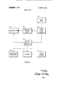
- FIG. 6 is a block diagram of a teaching machine incorporating the present invention.
- V FIG. 7 is a planabview of an altemative,storage' media frame format.
- a preferred embodiment of the teaching device of the present invention is generally referred to by the numeral 10. and is enclosed within a housing 12 on base 11.
- programmed media 13 which is preferably microfilm having encoded frames thereon.
- the front face 14 of housing 12 contains a rear projection viewing screen 16 that is preferably fabricated of a translucent material.
- a rectangular frame 18 having a recess 30 in which are mounted photodetector retainers 32 containing slideably mounted photodetectors 20-A through 20-F. Also mounted in the recess 30 of frame 18 are mirrors 22 as shown in FIG.
- FIG. 3 A preferred format for a frame of programmed storage media 13 is shown in FIG. 3.
- Programmed storage media 13 is positioned for movement through a scanning or reading station by a film gate 17.
- projection lens 26 Arranged between screen 16 and programmed media 13 is projection lens 26 which is mounted to housing 12 in optical alignment with the gate 17 and screen 16.
- Projection lamp 28 is connected to a suitable source of electrical potential (not shown) and emits light that passes through programmed media l3 and projection lens 26 to form an image on screen l6.
- a suitable source of electrical potential not shown
- the optical projection system selected is not part of the invention and alternative systems can be utilized by those skilled in the art.
- Correct and incorrect answer indicating lights 53, 55, 57 and 59 are shown preferably mounted on the base 11 but can be located in any area of the device viewable by the student.
- Removable modular printer 61 can be incorporated to provide a permanent printed record 63 of the student's performance. The printer need not be part of the teaching device but can be remotely positioned, such as at a teachers desk.
- FIG. 2a a simplified perspective view of a portion of the frame 18 in which photodetector retainers 32 are mounted is shown in the vicinity of photodetector 20-F.
- Frame 18 preferably has a rectangular recess or U-shaped channel 30 therein in which photodetector retainer 32 is slideably mounted.
- Photodetector retainer 32 has a cylindrical hole 34 therein at the bottom of which photodetector 20-F is located and is connected by wires (not shown) to associated logic circuitry. Examplary logic circuitry is discussed hereinbelow with reference to FIGS. 4 and 5.
- Cylindrical hole 34 acts as a light bafile for the light incident on photodetector 20-F, to insure that a selected light beam 29 from projection lamp 28 reflected from mirror 22 reaches photodetector 20-F, and that no appreciable ambient room light falls on photodetector 20-F.
- Photodetector retainer 32 can be made of black Lucite, metal, or other opaque material. The mounting of the remaining photodetectors is similar to that of photodetector 20-F which is used as an example.
- Frame 18 is preferably made of Lucite, glass or other transparent material.
- the portion of frame 18 holding the mirror can also be L-shaped and opaque although a transparent U-shaped recess 30 is shown. Too, the frame 18 need not be transparent if portions between the mirror and the light incident thereon from source 28 are cut out.
- the use of a transparent frame enables easy changing of mirror positions, adding mirrors or eliminating them.
- the mirrors need not be individually positionable and two sides of the screen can have continuous strip mirrors mounted there with photocells located on the other respective opposite two sides. Beam selection would then be by the retainers 32 with holes 34 containing the photocells.
- Other types of photodetectors and mirror mountings which can be substituted for those shown will be apparent to those skilled in the art.
- Prisms or other reflecting bodies can be substituted for the mirrors.
- a separate light source can be used to establish the beams or individual beam sources.
- Fiber optics can be used to provide beam sources.
- FIG. 3 a possible format for a frame of programmed media 13 is shown in which such media is a film 13 having an image area 36, encoded areas 38 and 39 and perforations 40. Encoded areas 38 and 39 correspond to photodetector positions on two sides of rectangular frame 18 seen in FIG. 1.
- Light rays A-F originate from projection lamp 28 and pass through programmed media 13 and projection lens 26 to reflect from the surface of mirrors 22 and impinge upon photodetectors 20-A through 20-F respectively.
- an electric circuit connected to the When an object such as a finger is placed in a position to interrupt the light paths to, preferably, at least two of the photodetectors, an electric circuit connected to the.
- photodetector is activated, as will be discussed hereinbelow with reference to FIG. 4.
- coded areas 38 and 39 of programmed media 13 seen in FIG. 3 one or more photodetectors can be blocked, reducing the number of intersecting beams under consideration for that particular frame of programmed media 13.
- Leads 4l-A through 4l-F of photodetectors 20-A through 20-F, respectively, are connected through resistors 44-A through 44-F, respectively, to the positive terminal of a DC voltage supply 42.
- Lead 43-A of, photodetector 20-A is connected to an input tenninal of AND gate 45, and to input terminal 66 of AND gate 49.
- Lead 43-3 of photodetector 20-8 is connected to input terminal 63 of AND gate 47 as well as to input terminal 69 of AND gate 51.
- Lead 43-E of photodetector 20-E is connected to input terminal 65 of AND gate 47 and to input terminal 62 of AND gate 45.
- Lead 43-F of photodetector 20-F is connected to input terminal 71 of AND gate SI and also to input terminal 68 of AND gate 49.
- the output leads from AND gates 45, 47, 49 and 51 are connected to the negative terminal of DC voltage supply 42 through individually associated lamps 53, 55 S7 and 59 respectively.
- the voltage drops across resistors 44-A and 44-D are therefore greater than the voltage drops across resistors 44-13, 44-C, 44-E and 44-F.
- the voltages at input terminals 61 and 62 of AND gate 45, input terminals 63, 64 and 65 of AND gate 41, input terminal, 68 O AN gate 49, and input terminals 69 and 71 of ANDgate 51 are higher than the voltages at input terminal 60 of AND gate 45;
- circuitry is shown that can be used with a teaching device incorporating the present invention utilizing 12 photodetectors 80-A through 80-L and yielding 32 possible light intersections.
- the negative lead of every photodetector 80-A through 80-L is connected to the negative terminal of DC voltage supply 82.
- the positive leads photodetectors 80-A through 80-L are connected through respective resistors 81-A through 81-L to the positive terminal of DC voltage supply 82.
- Positive leads from photodetectors 80-A are connected to input terminals 85, 97 and 99 of OR gates 120, 122 and 123 respectively.
- the positive terminal of photodetector 80-8 is connected to input terminals 86 and 98 of OR gates 120 and 122, respectively.
- Positive leads from photodetector 80-C are connected to input terminals 87 and 100 of OR gates 120 and 123, respectively.
- the positive terminal of photodetector 80-D is connected to input terminal 88 of OR gate 120.
- the positive terminal of photodetector 80-E is connected to input terminals 89, '101, 105 and 109 of OR gates 121, 124, 125 and 126, respectively.
- a positive lead from photodetector 80-F is connected to input terminal 90 of OR gate 125.
- the positive terminal of photodetector 80-G is connected to input terminals 91, 103 and 110 of OR gates 121, 124 and 126, respectively.
- the positive terminal of photodetector 80-I-l is connected to input terminal 92 of OR gate 121 and to input terminal 104 of OR gate 124.
- the positive terminal of photodetector 80-1 is connected to input terminals 93, 107 and 111 of OR gates 121, 125 and 126, respectively.
- the positive terminal of photodetector 80-.[ is connected to input terminal 94 of OR gate 121 and to input terminal 108 of OR gate 125.
- Positive leads from photodetector 80-K are connected to input terminal 95 of OR gate 121 and to input terminal 112 of OR gate 126.
- the positive terminal of photodetector 80-L is connected to input terminal 96 of OR gate 121. OR gates 120 and 121 input to AND gate 130 by lines 127 and 128, respectively.
- OR gate 120 The purpose of OR gate 120 is to detect if any vertical beam of light has been blocked, that is, if any one of photodetectors -A, 80-B, 80-C or 80-D has been darkened. Placing a finger on screen 16 so that no-light reaches photodetector 80-A makes the resistance of photodetector 80-A higher than the resistance of any of the photodetectors 80-8, 80-C or 80-D. The voltage drop across resistor 81-A is less than the voltage 1 drop across any of the resistors 81-B, 81-C or 81-D. Input terminal experiences a higher voltage than input terminals 86, 87, or 88 of OR gate 120.
- OR gate over line 127 is hence energized signifying that one of the vertical light beams has been interrupted. Analogous analyses can be made for when any of the photodetectors 80-B, 80-C or 80-D receive 81-1, 81-1, 81-K or 81-L, and hence the voltage appearing at input terminal 89 of OR gate 121 is higher than the voltage appearing at input terminals 90, 91, 92, 93, 94, 95 or 96 thereof.
- Line 128 is energized from OR gate 121 to signify that one horizontal light beam any one of the photodetectors 80-F, 80-G, 80-H, 80-l, 80-1, 80-K or 80-L receiving no light.
- AND gate 130 is has been interrupted. Similar analyses can be made for provided. Assuming line 127 is energized, signifying that any one of photoconductors 80-A through 80-D has been darkened, and also that line 128 is energized, signifying that any one of photoconductors 80-E through 80-L has been darkened, the output line 131 of AND gate 130 will be energized. Output 131 can be to an electric light such as 53, 55, 57 or 59as shown in FIG. 1 to indicate that an answer has been given.
- OR gate 122 is used to detect whether any beam of light on the left half of the screen has been blocked by determining whether either of photodetectors 80-A'or 80-B has been darkened. lf a finger is placed on screen 16 so that no light reaches photodetector 80-A, its resistance will be higher than the resistance of photodetector 80-B. The voltage drop across resistor 8l-A will be then less than the voltage drop across resistor 81-8, and hence the voltage at input terminal 97 will be higher than the voltage at input terminal 98 of OR gate 122. Therefore, OR gate [22 outputs over line 132, to
- OR gate 123 is provided.
- a finger placed on screen 16 so that no light reaches photodetector 80-A raises the resistance of photodetector 80-A so that it is higher than the resistance of photodetector 80-C.
- the voltage drop across resistor 8l-A is less than the voltage drop across resistor til-C, and hence the voltage at input terminal 99 of OR gate 123 is higher than the voltageappearing at input tenninal 100.
- OR gate 124 will determine whether any beam of light in the top half of screen 16 has been blocked, that is, if any one of photodetectors 80-E, 80-F, 80-6, or 80-H has been darkened. If a finger has been placed on screen l6 so that no light reaches photodetector 80-E, the resistance of photodetector 80-E is higher than the resistance of any of photodetectors 80-E, 80-6, or 80-l-l. The voltage drop across resistor 8l-E is therefore less than the voltage drop across any of the rethe voltage drop across any of the resistors 8l-F, 81-1 or 81-], and hence less than the voltage appearing at input terminal 106, 107. or 108 of OR gate 125.
- OR gate 125 over line 1-38 will signify that one of the light beams in the top half of either the top or bottom half of screen 16 has been interrupted.
- OR gate 126 is used. By placing a finger on screen so that no light reaches photodetector 80-E, the resistance of photodetector 80-E is raised to be higher than the resistance of any of the photodetectors 80-6, 80-1, or 80-K. The voltage drop across resistor 8l-E is now less than the voltage drop across any of the resistors 81-6, 81-], or Bl-K.
- the voltage at input terminal 109 is now higher than the voltage appearing at input terminals 110, 111, or 112, energizing OR gate 126 to output over line 140.
- the output of OR gate 124 over line 136 signifies that one of the light beams in the top half of screen 16 has been interrupted.
- Analogous analyses can be made for any one of the photoconductors 80-F, 80-6, or 80-H receiving no tors -E, 80-F, 80-l, or 80-J has been darkened. Assuming a finger has been placed on screen 16 so that no light reaches photodetector 80-E, the resistance of photoconductor 80-E will be higher than the resistance of any of the photodetectors 80-F, 80-1, or 80-J.
- the circuit shown in Fl6,. 5 is capable of indicating 32 intersections. It will be appreciated by one skilled in theart that the addition of eachadditional OR gate doubles the number of defined positions.
- the number of photodetectors required is equal to two times the square root of the desired number of intersections, for example, 32 photodetectors are needed to indicate 256 intersections.
- Photodetectors such as 20A-20F or 80A-80L are represented by block 150. Controlling inputs to the photodetectors is photodetector enabling lock 152 which can be that shown in FIGS. 4 or 5. esponse. correlating comparator 154 can also be that shown in FIGS. 4 and 5 or may be a program controlled logic as is well known by those skilled in the art. Comparator 154 compares the output of photodetectors and frame code reader 156 for reading coded frame 158 which can be of the format shown in FIG. 3. The coding on the frame displayed controls through enabling circuit 152 which photodetectors in block 150 are operatively connected to comparator 154. Comparator 154 can output to student responsecorrectness indicators such as lights 53, 55, 57 and 59, a response recorder 161 such as the printer 61 and a frame advancement mechanism 162.
- student responsecorrectness indicators such as lights 53, 55, 57 and 59
- a response recorder 161 such as the printer 61 and a frame advancement mechanism 16
- a storage medium 13 having perforations 40 and code format 150 which has several distinct answer columns or areas 152 rather than intersections can be used.
- a set of parallel light beams extending across the display screen between two opposite sides or, as is shown, from top to the bottom of frame 18 is provided. An interruption of one of the beams can be registered by a finger or other object. If one photodetector is enabled, when the light to it is cut off, a correct response is registered.
- An operator responsive device having a projection lamp and screen for displaying information from a response encoded programmed storage medium bearing encoding corresponding to the displayed information, said device comprising:
- photodetectors positioned to receive light from said light beams provided such light beams remain uninterrupted by an operator response
- circuit means operatively connected to the photodetectors and responsive to the encoded medium for comparing an operator response to the encoding which corresponds to the information displayed;
- circuit means operatively connected to said circuit means for producing signals representative of the result of comparisons made by said circuit means.
- said light beam forming and directing means comprises means for reflecting light beams adjacent to and transversing said display screen.
- a teaching machine having a projection lamp and screen for displaying information from a response encoded programmed media containing questions and encoded answers stored thereon, said machine comprismg:
- photodetectors positioned to receive light directed across the front of said display screen
- said light comprises a grid of light beams across and closely spaced from the front face of said display screen.
- a display device having a projection lamp, a media moving mechanism and a screen for displaying information from a response encoded programmed media, said device comprising:
- photodetectors positioned to receive said light having outputs in accordance with the amount of light impinging thereon;
- photodetectors having outputs corresponding to light impinging thereon
- third circuit means for indicating the correctness of a student response, such that when a student response is registered, said second circuit means enables both said first circuit means to move the media in accordance with the comparison results and said third circuit means to indicate the correctness of the student response.
- said third circuit means comprises means for indicating a correct response and means for indicating an incorrect response.
- said third circuit means comprises means for recording the correctness of a student response.
- An operator responsive device having a media moving mechanism, a projection lamp and a screen for displaying information from a response encoded programmed media, said device comprising:
- photodetectors positioned to receive light beams from the lamp directed transversely across and adjacent said screen;
- first circuit means for illuminating said photodetectors with light from said lamp;
- comparison means for comparing the outputs of said first and second circuit means and for actuating the media moving mechanism in accordance with the result. of the comparison, such that when information is displayed and a response is registered by an operator initiated interruption of at least one of said light beams, said media moving mechanism is actuated and said media is moved in accordance with the program and the operator response.
- the device of claim 9 further comprising means to said comparison means.
- the device of claim 9 further comprising means directing light beams from the lamp across the face for indicating an incorrect response operatively conofthe screen to selectively located photodetectors;
- the device of claim 9 further comprising means for recording the response.
- the method (if usmg a :eacnng mach ne havirt g a light beam interruption; and pro-lee amp an screen or aymg m moving the media in response to comparison of enfrom response encoded programmed media, said coding corresponding to the displayed information method comprising. d h 0d t t t t displaying response encoded information on the 10 an F 0t e so or Pu screen;
Landscapes
- Engineering & Computer Science (AREA)
- Theoretical Computer Science (AREA)
- Business, Economics & Management (AREA)
- Physics & Mathematics (AREA)
- Educational Administration (AREA)
- Educational Technology (AREA)
- General Physics & Mathematics (AREA)
- Electrically Operated Instructional Devices (AREA)
Applications Claiming Priority (1)
| Application Number | Priority Date | Filing Date | Title |
|---|---|---|---|
| US10927671A | 1971-01-25 | 1971-01-25 |
Publications (1)
| Publication Number | Publication Date |
|---|---|
| US3698100A true US3698100A (en) | 1972-10-17 |
Family
ID=22326796
Family Applications (1)
| Application Number | Title | Priority Date | Filing Date |
|---|---|---|---|
| US109276A Expired - Lifetime US3698100A (en) | 1971-01-25 | 1971-01-25 | Operator responsive programmed learning apparatus |
Country Status (4)
| Country | Link |
|---|---|
| US (1) | US3698100A (OSRAM) |
| AU (1) | AU464725B2 (OSRAM) |
| FR (1) | FR2124825A5 (OSRAM) |
| GB (1) | GB1373426A (OSRAM) |
Cited By (5)
| Publication number | Priority date | Publication date | Assignee | Title |
|---|---|---|---|---|
| US3837093A (en) * | 1972-05-25 | 1974-09-24 | Ceske Vysoke Uceni Tech | Apparatus for the determination of the quality of a pupil{40 s response |
| US4001948A (en) * | 1975-09-29 | 1977-01-11 | Stanley Wolfe | Light response teaching system |
| US4205462A (en) * | 1978-05-30 | 1980-06-03 | Training Associates, Inc. | Scheme training apparatus for teaching mail sorting and the like |
| US4351591A (en) * | 1979-12-03 | 1982-09-28 | Logicon, Inc. | Merchandising terminal |
| US4425099A (en) | 1981-10-13 | 1984-01-10 | Texas Instruments Incorporated | Educational aid for use with workbook |
Citations (4)
| Publication number | Priority date | Publication date | Assignee | Title |
|---|---|---|---|---|
| US3137948A (en) * | 1960-08-17 | 1964-06-23 | Teaching Machines Inc | Teaching machines |
| US3382588A (en) * | 1965-01-11 | 1968-05-14 | Educational Testing Service | Response expression apparatus for teaching machines |
| US3522664A (en) * | 1967-11-20 | 1970-08-04 | Westinghouse Electric Corp | Interface device and display system |
| US3596376A (en) * | 1968-05-02 | 1971-08-03 | Gaston Avedissian | Aptitude testing machine |
-
1971
- 1971-01-25 US US109276A patent/US3698100A/en not_active Expired - Lifetime
-
1972
- 1972-01-20 GB GB282172A patent/GB1373426A/en not_active Expired
- 1972-01-24 AU AU38237/72A patent/AU464725B2/en not_active Expired
- 1972-01-25 FR FR7202306A patent/FR2124825A5/fr not_active Expired
Patent Citations (4)
| Publication number | Priority date | Publication date | Assignee | Title |
|---|---|---|---|---|
| US3137948A (en) * | 1960-08-17 | 1964-06-23 | Teaching Machines Inc | Teaching machines |
| US3382588A (en) * | 1965-01-11 | 1968-05-14 | Educational Testing Service | Response expression apparatus for teaching machines |
| US3522664A (en) * | 1967-11-20 | 1970-08-04 | Westinghouse Electric Corp | Interface device and display system |
| US3596376A (en) * | 1968-05-02 | 1971-08-03 | Gaston Avedissian | Aptitude testing machine |
Cited By (5)
| Publication number | Priority date | Publication date | Assignee | Title |
|---|---|---|---|---|
| US3837093A (en) * | 1972-05-25 | 1974-09-24 | Ceske Vysoke Uceni Tech | Apparatus for the determination of the quality of a pupil{40 s response |
| US4001948A (en) * | 1975-09-29 | 1977-01-11 | Stanley Wolfe | Light response teaching system |
| US4205462A (en) * | 1978-05-30 | 1980-06-03 | Training Associates, Inc. | Scheme training apparatus for teaching mail sorting and the like |
| US4351591A (en) * | 1979-12-03 | 1982-09-28 | Logicon, Inc. | Merchandising terminal |
| US4425099A (en) | 1981-10-13 | 1984-01-10 | Texas Instruments Incorporated | Educational aid for use with workbook |
Also Published As
| Publication number | Publication date |
|---|---|
| AU3823772A (en) | 1973-07-26 |
| GB1373426A (en) | 1974-11-13 |
| AU464725B2 (en) | 1975-09-04 |
| DE2203202B2 (de) | 1976-03-11 |
| FR2124825A5 (OSRAM) | 1972-09-22 |
| DE2203202A1 (de) | 1972-08-10 |
Similar Documents
| Publication | Publication Date | Title |
|---|---|---|
| US3408749A (en) | Branching-instruction teaching device | |
| US4968255A (en) | Electronic instructional apparatus | |
| US3052041A (en) | Teaching machine | |
| US3501851A (en) | Method and apparatus for teaching | |
| US3838525A (en) | Visual teaching device | |
| US3932948A (en) | Audio-visual learning system | |
| US3665615A (en) | Teaching machine in which instruction items are projected by an image projector | |
| US3395464A (en) | Teaching machine systems | |
| US3121960A (en) | Educational device | |
| US3984923A (en) | System and process for preschool screening of children | |
| US2402162A (en) | Educational device | |
| US3520074A (en) | Instruction system providing permanent records | |
| US3698100A (en) | Operator responsive programmed learning apparatus | |
| US3724097A (en) | Programmed audio-visual presentation of information for instruction in the operation of keyboard controlled instruments | |
| US4378217A (en) | Terminal trainer keyboard and display apparatus for teaching keyboard operations and knowledge items | |
| US3992092A (en) | Microfilm instruction system | |
| US3775864A (en) | Response-evoking apparatus | |
| US3570146A (en) | System for automatically testing applicants | |
| US4205462A (en) | Scheme training apparatus for teaching mail sorting and the like | |
| US3538622A (en) | Teaching device | |
| US3137948A (en) | Teaching machines | |
| US3344534A (en) | Teaching apparatus | |
| GB1195092A (en) | Improvements in or relating to Educational Testing Apparatus. | |
| US3666872A (en) | Teaching machine | |
| US3810317A (en) | Display systems |