US3693604A - Resonant energy-conversion systems with fluid-energy inputs - Google Patents
Resonant energy-conversion systems with fluid-energy inputs Download PDFInfo
- Publication number
- US3693604A US3693604A US94063A US3693604DA US3693604A US 3693604 A US3693604 A US 3693604A US 94063 A US94063 A US 94063A US 3693604D A US3693604D A US 3693604DA US 3693604 A US3693604 A US 3693604A
- Authority
- US
- United States
- Prior art keywords
- converter
- chamber
- fluid
- energy
- piston
- Prior art date
- Legal status (The legal status is an assumption and is not a legal conclusion. Google has not performed a legal analysis and makes no representation as to the accuracy of the status listed.)
- Expired - Lifetime
Links
- 238000006243 chemical reaction Methods 0.000 title abstract description 8
- 239000012530 fluid Substances 0.000 claims abstract description 35
- 239000000203 mixture Substances 0.000 claims description 16
- 238000002485 combustion reaction Methods 0.000 claims description 15
- 230000006835 compression Effects 0.000 claims description 10
- 238000007906 compression Methods 0.000 claims description 10
- 238000002347 injection Methods 0.000 claims description 6
- 239000007924 injection Substances 0.000 claims description 6
- 238000005086 pumping Methods 0.000 claims description 6
- 230000000295 complement effect Effects 0.000 claims description 5
- 238000000605 extraction Methods 0.000 claims description 4
- 230000001105 regulatory effect Effects 0.000 claims description 2
- 235000014676 Phragmites communis Nutrition 0.000 description 20
- 239000007789 gas Substances 0.000 description 19
- 239000000446 fuel Substances 0.000 description 8
- 230000007246 mechanism Effects 0.000 description 7
- 230000003534 oscillatory effect Effects 0.000 description 6
- 238000003491 array Methods 0.000 description 5
- 230000008859 change Effects 0.000 description 5
- 238000013461 design Methods 0.000 description 5
- 238000012546 transfer Methods 0.000 description 5
- 125000004122 cyclic group Chemical group 0.000 description 4
- 230000001351 cycling effect Effects 0.000 description 4
- 230000000694 effects Effects 0.000 description 3
- 206010016256 fatigue Diseases 0.000 description 3
- 239000000314 lubricant Substances 0.000 description 3
- 239000000463 material Substances 0.000 description 3
- 230000000051 modifying effect Effects 0.000 description 3
- 230000010355 oscillation Effects 0.000 description 3
- XEEYBQQBJWHFJM-UHFFFAOYSA-N Iron Chemical compound [Fe] XEEYBQQBJWHFJM-UHFFFAOYSA-N 0.000 description 2
- 230000009471 action Effects 0.000 description 2
- 238000013459 approach Methods 0.000 description 2
- 230000001939 inductive effect Effects 0.000 description 2
- 239000002184 metal Substances 0.000 description 2
- 229910052751 metal Inorganic materials 0.000 description 2
- 238000000034 method Methods 0.000 description 2
- 239000007800 oxidant agent Substances 0.000 description 2
- 230000036316 preload Effects 0.000 description 2
- 230000004044 response Effects 0.000 description 2
- 230000000630 rising effect Effects 0.000 description 2
- 238000007789 sealing Methods 0.000 description 2
- 238000000926 separation method Methods 0.000 description 2
- RYGMFSIKBFXOCR-UHFFFAOYSA-N Copper Chemical compound [Cu] RYGMFSIKBFXOCR-UHFFFAOYSA-N 0.000 description 1
- 244000089486 Phragmites australis subsp australis Species 0.000 description 1
- 229910000831 Steel Inorganic materials 0.000 description 1
- RTAQQCXQSZGOHL-UHFFFAOYSA-N Titanium Chemical compound [Ti] RTAQQCXQSZGOHL-UHFFFAOYSA-N 0.000 description 1
- 238000005452 bending Methods 0.000 description 1
- 230000008901 benefit Effects 0.000 description 1
- 230000000903 blocking effect Effects 0.000 description 1
- 230000003197 catalytic effect Effects 0.000 description 1
- 239000000919 ceramic Substances 0.000 description 1
- 239000000567 combustion gas Substances 0.000 description 1
- 238000007596 consolidation process Methods 0.000 description 1
- 238000011109 contamination Methods 0.000 description 1
- 229910052802 copper Inorganic materials 0.000 description 1
- 239000010949 copper Substances 0.000 description 1
- 230000008878 coupling Effects 0.000 description 1
- 238000010168 coupling process Methods 0.000 description 1
- 238000005859 coupling reaction Methods 0.000 description 1
- 238000013016 damping Methods 0.000 description 1
- 230000001419 dependent effect Effects 0.000 description 1
- 238000007599 discharging Methods 0.000 description 1
- 238000006073 displacement reaction Methods 0.000 description 1
- 230000009977 dual effect Effects 0.000 description 1
- 230000005611 electricity Effects 0.000 description 1
- NBVXSUQYWXRMNV-UHFFFAOYSA-N fluoromethane Chemical compound FC NBVXSUQYWXRMNV-UHFFFAOYSA-N 0.000 description 1
- 210000004907 gland Anatomy 0.000 description 1
- 238000003306 harvesting Methods 0.000 description 1
- 229910052742 iron Inorganic materials 0.000 description 1
- HFGPZNIAWCZYJU-UHFFFAOYSA-N lead zirconate titanate Chemical compound [O-2].[O-2].[O-2].[O-2].[O-2].[Ti+4].[Zr+4].[Pb+2] HFGPZNIAWCZYJU-UHFFFAOYSA-N 0.000 description 1
- 230000000670 limiting effect Effects 0.000 description 1
- 238000012423 maintenance Methods 0.000 description 1
- 238000005272 metallurgy Methods 0.000 description 1
- 150000002739 metals Chemical class 0.000 description 1
- 230000001590 oxidative effect Effects 0.000 description 1
- 230000036961 partial effect Effects 0.000 description 1
- 238000005381 potential energy Methods 0.000 description 1
- 230000008569 process Effects 0.000 description 1
- 238000012545 processing Methods 0.000 description 1
- 230000002829 reductive effect Effects 0.000 description 1
- 230000029058 respiratory gaseous exchange Effects 0.000 description 1
- 230000000284 resting effect Effects 0.000 description 1
- 230000000452 restraining effect Effects 0.000 description 1
- 230000002000 scavenging effect Effects 0.000 description 1
- 230000003068 static effect Effects 0.000 description 1
- 239000010959 steel Substances 0.000 description 1
- 230000001360 synchronised effect Effects 0.000 description 1
- 239000002699 waste material Substances 0.000 description 1
- 238000003466 welding Methods 0.000 description 1
Images


Classifications
-
- F—MECHANICAL ENGINEERING; LIGHTING; HEATING; WEAPONS; BLASTING
- F01—MACHINES OR ENGINES IN GENERAL; ENGINE PLANTS IN GENERAL; STEAM ENGINES
- F01B—MACHINES OR ENGINES, IN GENERAL OR OF POSITIVE-DISPLACEMENT TYPE, e.g. STEAM ENGINES
- F01B7/00—Machines or engines with two or more pistons reciprocating within same cylinder or within essentially coaxial cylinders
- F01B7/20—Machines or engines with two or more pistons reciprocating within same cylinder or within essentially coaxial cylinders with two or more pistons reciprocating one within another, e.g. one piston forming cylinder of the other
-
- G—PHYSICS
- G10—MUSICAL INSTRUMENTS; ACOUSTICS
- G10K—SOUND-PRODUCING DEVICES; METHODS OR DEVICES FOR PROTECTING AGAINST, OR FOR DAMPING, NOISE OR OTHER ACOUSTIC WAVES IN GENERAL; ACOUSTICS NOT OTHERWISE PROVIDED FOR
- G10K5/00—Whistles
-
- H—ELECTRICITY
- H02—GENERATION; CONVERSION OR DISTRIBUTION OF ELECTRIC POWER
- H02N—ELECTRIC MACHINES NOT OTHERWISE PROVIDED FOR
- H02N11/00—Generators or motors not provided for elsewhere; Alleged perpetua mobilia obtained by electric or magnetic means
- H02N11/002—Generators
-
- F—MECHANICAL ENGINEERING; LIGHTING; HEATING; WEAPONS; BLASTING
- F02—COMBUSTION ENGINES; HOT-GAS OR COMBUSTION-PRODUCT ENGINE PLANTS
- F02B—INTERNAL-COMBUSTION PISTON ENGINES; COMBUSTION ENGINES IN GENERAL
- F02B75/00—Other engines
- F02B75/02—Engines characterised by their cycles, e.g. six-stroke
- F02B2075/022—Engines characterised by their cycles, e.g. six-stroke having less than six strokes per cycle
- F02B2075/025—Engines characterised by their cycles, e.g. six-stroke having less than six strokes per cycle two
-
- F—MECHANICAL ENGINEERING; LIGHTING; HEATING; WEAPONS; BLASTING
- F02—COMBUSTION ENGINES; HOT-GAS OR COMBUSTION-PRODUCT ENGINE PLANTS
- F02B—INTERNAL-COMBUSTION PISTON ENGINES; COMBUSTION ENGINES IN GENERAL
- F02B59/00—Internal-combustion aspects of other reciprocating-piston engines with movable, e.g. oscillating, cylinders
Definitions
- ABSTRACT ABSTRACT (g1. us/119F353 [SOs/[86$ Resonant energy conversionsystemsinvowing high), 58 Field of Search ..60/39.6;3l0/8.1,8.2, 8.3, mustanbfrequencymechamcalapparamsand ing for energy conversion from fluid sources to mechanical, hydraulic and electrical outputs.
- FIG. 2A is an illustration of the relationship of a blade-nozzle arrangement of the character of FIG. 2 to a representative converter drawn to a scale similar to that of FIG. 7.
- FIG. 3 is a drawing of a second version of an oscillatory blade-nozzle mechanism for injecting energy into a resonant energy converter.
- FIG. 3A is an illustration of the relationship of a blade-nozzle arrangement of the character of FIG. 3 to a representative converter drawn to a scale similar to that of FIGS. 2A and 7.
- FIG. 3B is a fragmentary view, perpendicular to the plane of FIG. 3A, of the mid-portion of the meridional member of the converter of FIG. 3A.
- FIG. 4 is a cross-sectional elevation of an expansionchamber/piston arrangement for converting energy contained'in gases into mechanical motion.
- FIG. 5 is a partly section view of the arrangement of FIG. 4 from the left.
- FIG. 6 is a cross section FIG. 4.
- FIG. 7 is an elevation that contrasts the size of the engine portion, seen in FIGS. 4-6, with the overall size perpendicular to the view of of the converter.
- FIG. 7A is a view of the converter of FIG. 7 taken from a plane at a right angle to the viewing plane of FIG. 7.
- FIG. 8 shows the piston FIG. 4 elastically displaced toward one end of the expansion chamber.
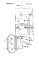
- FIG. 9 is a cross-sectional elevation of a two-strokecycle combination engine-pump in accordance with this invention.
- FIG. 10 is a fragmentary elevation of an engine similar to that of FIG. 9, except that is width is greater than one familiar with prior arts might infer from FIG. 9.
- FIG. 11 is a fragmentary elevation of still another kind of engine taken from an aspect comparable with that ofFIG. 10. k
- FIG. 1 there is outlined a resonantenergy converter of the character introduced in parent Application Ser. No. 654,569.
- Member 21, 22, 23 will be recognized as a pair of quarterwave mechanical transformer 21 and 23, joined at their small or low impedance end 22 into a continuous half-wave bar.
- Such a bar if compressed between its large high-impedance nodal' ends, can to energy fairly efficiently at its resonant frequency with a properly-designed compressing structure. If one or two electromechanical or electro-acoustic transducers 24, 25 are interposed between the ends of the member 21, 22, 23 and the externally compressing structure, the member can receive and transform energy from the transducer 24, 25, provided that the latter are energized a half wavelength apart at the frequency at which member 21, 22, 23 is resonant and provided that too much energy is not delivered to supporting structure. In such event, the excursion at midpoint 22 will be greater than the motion at either end by a factor approximately equal to the square root of the quotient of the large area at an end divided by the small area at midpoint 22.
- an outer resonant member 27, 28, 29, 30, 31, can be designed to straddle and balance in tension the compressive preload it imposes upon member 21, 22, 23 and to be resonant at the same frequency as that member.
- advantage may be taken of the fact that the velocity of sound is higher in certain materials.
- the outer member would ordinarily be constructed of material having the higher inherent velocity because of the somewhat greater physical length of the sound path in the tensile member. It can be configured as a pair of half-wave legs aligned side by side and separated by the member under compression but linked together by a heavy stiff nodal portion. Supporting structure for such an array is usually fastened to its close to one or both nodes as shown.
- the actual node may vary slightly in position from the predicted spot ormay be somewhat diffuse; but, ideally, it will be within the relatively. short transducers 24, 25, which have been interposed in FIG. 1.
- the array of half-wave members when so excited, the array of half-wave members will be found to resonate with the center portions of the outer legs of the balancing tensile member in phase with each other but out of phase with the compressed one by l80 that is to say, always moving in the opposite direction.
- a reciprocating tool may now be designed to be positioned and mechanically connected between the midpoint of the inner member and one or both midpoints of the outer one.
- a reciprocating engine may be designed for emplacement therebetween, with its stroke equal to the greatest interval between the cycling midpoints.
- transducers of the character of polarized led titanate zirconate preferably of the high-dynamic-strain type known as PZT-4, reversibly generate constantfrequency ac power. Cycling frequencies of such engines are likely to be much higher than the frequencies usually associated with engines that turn shafts.
- the transducers24, 25 are designed to have large spacing between their oppositely polarized electrodes, and if the engines and members are so designed as to match and be fully compatible therewith, the output will be high-voltage ac; and comparatively little copper and iron will be needed for the relatively high frequency electric motors that can be powered thereby. Thus, converters are likely to be found applicable to selfpowered vehicles.
- Transducers may be eliminated together when the function of the converter is not to yield electricity but only to operate directly a machine or mechanism such as a pump. It is, or course, also reasonable to design the engine and converter to power both a pump and a pair of transducers.
- FIG. 2 FIG. 44 in the parent application
- a device for putting a mechanicalenergy input into a resonant-energy converter only the midpoints of whose resonating members 34, 35 and 36, 37 show in FIG. 2.
- a fluid which reasonably may be air at a suitable elevated pressure, say 30 psig or more, is fed from flexible hose 40 to expansion nozzle 38 for discharge therefrom. Since the pressure differential is greater than that required for reaching nozzle velocities in the sonic region, slight variation in the input pressure will not cause serious fluctuations in the relatively constant nozzle flow.
- Nozzle 38 Under the influence of sonic flow, reed 39, which may be a relatively stiff device with a highnatural frequency, begins to resonate, soon putting the entire length (shown in FIG. 2A) of member 34, 35 into resonance and building up it amplitude of oscillatory motion quickly to the point at which it tends to reduce alternately the gaps 41, 42 on either of its sideswithin nozzle 38. Nozzle 38 likewise tends to oscillate as a consequence of the resultant cyclical pressure variations against its walls.
- the partial closures of the two competing passages intensify the cyclical pressure variations on the opposite tapered surfaces of the reed 39, and thus, the reed dances at increasingly higher amplitudes in consequence of the energy it continues to receive from the expanding jets that rush past it alternately on eight side, until it may even begin to rap alternately upon the opposite nozzle walls, with consequent risk of inducing early fatigue failure unless some of the energy is taken from it.
- the oscillatory dance of the reed and nozzle will put the members 34, 35 and 36, 37 into oppositely phased longitudinal resonance, causing the transducers at the nodes to feel cyclically compressive forces equal to, say, 10 or more times the force maxima occurring between the reed and nozzle (through the amplitudes at the transducers are correspondingly less).
- the area at the large end of the members is at least a hundred times the tapered-down members cross-sectional area immediately adjacent to the nozzle.
- the compressive yield of the transducer is one-four thousands or 0.00025 inch. Par of the energy of deformation may be drawn from the transducer by a resistive electrical load.
- the force change at member midlength will be 200 pounds, resulting in a cyclical stress change of 200/0.01
- the nozzle portion 38 is situated in the verymiddle of half-wave member 127, 36, 37, 129,-which represents a consolidation of the outer members of symbolic FIG. 1, in general accordance withthe more specific structure of FIGS. 16 and 17 of parent US. Pat. NO. 3,558,936
- Resonant reed or blade portion 39 is located at the loop of the meridional member 34, 35, which here opposes the outer members in the customary fashion. Additional pairs of nozzle and reed means may optionally be coupled at the respective midpoint areas of the outer member and the meridional member.
- the input of energy via resonant reciprocation between the reed and nozzle provides resonant compression of transducers represented by 24 and 25 of FIG. 1, here indicated as transducers 124 and 125, with resultant high-frequency, high-voltage electrical output therefrom.
- FIGS. 3A and 3B in connection with FIGS. 1 and 3, the converter here is of the flexurally resonant type.
- FIG. 1 again serves symbolically, as in parent U.S. Pat. No. 3,558,936,for all converters, regardless of the mode of resonance, whether longitudinal, flexural, or torsional.
- the flexural resonance of FIGS. 3, 3A, and 3B is of the character seen in FIGS. 37, 38, 39, and 45 of the parent.
- the principal structural distinction, aside from the distinctively lowfrequency resonance mode for which flexural converters are proportioned, is that the transducers are arrayed in pairs as in FIG.
- transducer combinations of FIGS. 37 and 38 of the parent were conceived for use in these flexural converters.
- the meridional member 45, 46 of FIG. 3A first flexes so that its midpoint moved left and then toward the right on each cycle.
- the right leg 48 is also coupled to the left one to form the opposite wall of the nozzle and keep the width thereofconstant, so it flexes in the same direction as does the left leg, first departing from and then approaching the meridional member.
- the meridional member carries the reed 105A
- the symmetrically arrayed halves 47, 48 of the outer member array provide the reciprocally oscillating walls of the nozzle, between which the reed 105A itself oscillates. It is the purpose of the array of reed-nozzle combinations used in any converter to accomplish their motion in resonance. As seen in FIG.
- a plurality of reeds 105A, 105B may be includedalong the width of the meridional member; and alternating ones may be fed with fluids from the opposite sides, through all will resonate in phase and will oppose phased-together nozzles carried by the outer member array.
- FIGS. 4, 5, 6, 7, and 8 the cross section in FIG. 4 reveals a piston plate 51 resting midway between he longitudinal end walls 52, 53 of the expansion chamber 55, such as is often termed as cylinder.
- the expansion chambers of this invention need not be conventional right circular cylinders like those required in most piston-equipped engines. Moreover, achieving power strokes in both directions is far more convenient here than in engines equipped with rotating crankshafts.
- a single-chamber engine of I this type can have more power strokes per unit time than does a multicylinder crankshaft engine. The uneven put-put character of ordinary single cylinder engines will not be observed.
- any reasonable form of chamber preferably one designed to provide a relatively uniform travel distance for most of the expanding gases may be used.
- a rectangular chamber; having inlet and exhaust port arrays extending fully length along the opposite long sides might be best from a theoretical standpoint except that the maintenance of seals at the corners of the piston might become difficult.
- the chamber shown is a compromise.
- the chamber wall outline 54 and piston 51 have greater projected dimensions in FIG. 5 than in FIG. 4.
- the actual cross-sectional shape of the expansion chamber is seen in FIG. 6 to be generally oblong with semicircular walls in place of the short sides.
- Dimension W in FIG. 6 may be increased virtually without limit if dimensions P and Q, be widths of the respective manifolds 64 and 65 containing the inlet and exhaust port arrays, are similarly increased so that the resulting flow is substantially from left to right in FIGS. 4, 6, and 8.
- piston 51 travels vertically upwardly while the walls 52, 53 and 54 of chamber 55 move down.
- Inlet manifold 64 in coupled by non-resonant 74 to nodes 66 and 71 of FIG. 7; so it remains fixed while piston 51 and chamber 55 oscillate between extremes of their excursrons.
- the inlet manifold 64 at the left of FIGS. 4, 6, and 8 is seen to have a pair of ports 78, 79 that register alternately with one of two ports 80, 81, located at either end of expansion chamber 55.
- Registry of chamber port 80 with valve port 78 alternates with registry of chamber port 81 next to valve port 79, as the chamber 55 oscillates between its two extreme positions.
- the piston 51 also reached the extreme position in its antiparallel motion, bringing it close to one or the other of the chamber end walls 52 and 53.
- the piston-end wall clearance becomes least when the respective valve port registers with the respective cylinder port just prior to the resulting expansion of that clearance that is enforced by the changing sign of the elastic wave transiting through the resonant structure and reenforced by introduction of the compressed gas mixture.
- FIG. -7 also shows the inlet manifold 64 silhouetted against the chamber wall 54.
- the half-wave transformer member 67, 68 swells in a bi-directional taper toward a pair of heavy nodal ends 66, 71, located, as seen in FIG. 7, equidistantly removed from the relatively small engine portion at midlength.
- the scale and position of the small engine portion of the very long resonant energy converter 63 may be inferred from FIG. 7, through the size ratio is actually even greater.
- the elongated shape of the overall converter assembly makes it evident that, in vehicular application, these converters will ordinarily be aligned longitudinally.
- the nodal ends 66, 71 of member 67,68 interface respectively with hidden transducers 69, 72, which, in turn, respectively interface also with the heavy ends 70, 73 of the inner member of the converter, also a half-wave transformer pair 70, 56, 51, 58, 57, 73.
- the outer half-wave pair has for its central junction the aforementioned expansion-chamber wall structure 52, 53, 54.
- the end walls 52, 53 have seals 76 to prevent fluid leakage along the multiple rod components 58 that permit'transverse gas flow between them while coupling reciprocating piston 51 to the mechanical transformers 56, 57.
- the expansion chamber 55 is of circular cross section, only one rod component 58 will ordinarily be used.
- the intake manifold 64 has a constant position, unaffected by the cycling motion of piston 51 and chamber 55, the position of the exhaust valve array 65 is here made to lag the chamber 55, upon whose motion it is generally dependent.
- the exhaust manifold 65 is supported on the wall 54 of chamber 55, being held there by a pair of gibs 59, seen in FIG. 6. It is maintained in a centered aspect when sidewall 54 is at rest by a pair of opposed springs 94, 94, located in dashpot 95, wherein the fluid tends to damp out any tendency toward instability of oscillation of manifold 65.
- inlet ports 79, 81 come into registry with each other directly across from exhaust port 91, and although inlet ports 78, next come into mutual registry opposite exhaust port 90, the gas does not flow directly across the chamber 55 to an opposite port because exhaust-valve outlets ports 92 and 93, respectively, will at such times be moved out of alignment with respective ports and 91 when gas (orvapor) is being admitted to the respective same side of piston 51.
- exhaust-valve outlets ports 92 and 93 respectively
- the motion of the mechanical transformers, and, therefore, of the piston 51 and chamber 55 is basically simple harmonic, modified by inertia effects and by non-uniformities of power input and load.
- One such modifying effect results from the manner in which exhaust manifold 65 is coupled to the chamber 55.
- exhaust ports 90 and 92 likewise come into registry, permitting all chamber contents above piston 51 to be discharged while the piston 51 is moving upwardly in response to gas admission and expansion from below.
- the entry of energy-laden fluid via registration of inlet-valve ports 78 and 80 above piston plate 51 is accompanied by the arrival of exhaust port '93 adjacent port 91, now in registry for expulsion of expanded gas below piston 51.
- valve timing can be adjusted for modifying performance and even for switching to other thermodynamic cycling patterns.
- piston 51 is located at the juncture of upper and lower inner transformers, or at the mid-point of the meridional member of the converter.
- Piston 51 and its sealing piston rods 58 are situated between upper transformer 56 and lower transformer 57, the entire piston-rod-and-transformer array 51, 58, 56, 57 comprising the meridional member, which is hidden in FIG. 7 but appears in FIG. 7A, an elevation viewed from the right.
- the expansion chamber 55 in which piston 51 reciprocates, has a wall portion 54 that is limited by longitudinal end walls 52, 53. Chamber 52, 53, 54, 5 5 reciprocates with an oscillatory motion that is antiparallel to that of piston 51. Like the piston-rod combination 51, 58, chamber 52, 53, 54, 55 is supported between its own upper 67 and lower 68 transformers that enclose the piston transformers 56 and 57.
- Structure 71 upon which the converter is supported, is preferably fastened to the ends of the outer members of the converter, endwise of the nodes, where the amplitude of resonance is least.
- care is required when the support point are close to the brittle transducers, lest they be unevenly stressed and thus subjected to bending fracture.
- the inlet manifold 64 terminates the supply pipe 61, carrying the hot gas or steam from the stationary combustor or steam generator 60.
- piston rod 58,- 58 and transformer leg 57 seen below the combustion chamber end wall 53 in FIG. is the mirror image of the hidden junction of the same rods 58, 58 with the upper transformer leg 56.
- These rods 58 and the piston '51 together form the relatively small mechanical junction at the loop of resonating half-wave transformer pair 56, 57 whose ends 70, 73 terminate the meridional member thus constituted andabutthe transducers 69, 72.
- the mechanical transformers may be called on to perform valving and other tasks, which asks may draw considerable energy perhaps for short intervals, causing the delivery of complex forms to the transducers, locally overstressing some part of the mechanism, or inducing fatigue at a critical section.
- the high resonant frequency of the converters contributes to the criticality of stress build-up, as does the fact that the presence to the engine at the midpoint of the converter itself results in abrupt changes of section at the very point where the transformers are most slender.
- the converters are inherently constant-frequency devices, variable amplitudes reflecting changes in power levels or changes in the'magnitude of energy transfer, say to or from the transducers 69, 72, for example. Cdnverters are started from rest and will begin oscillating at constant frequency almost immediately.
- One way of starting the engine is to jack the transformers mechanically apart in whatever direction they have been designed to oscillate, while feeding the compressed fluids or the appropriate combinations of fuels and oxidants as the jacking force in unlatched and before the amplitudes of transformer'oscillation become degraded to a low value. It is also possible to feed fuel (or vapor, of compressed gas) in such a manner that the transformers will being to resonate at small amplitude from the rest position and increase to higher amplitudeat constant frequency. This may require that special valving arrangements be employed during starting and'th'at a shift be made to the continuous-duty valving as the stored energy builds up.
- the piston-travel speeds in the converters can be quiet great, the number of cycles or strokes per second being limited by flame propagation or gas-expansion velocities within the chamber rather than by the inertia forces that are developed in pistons, bearings, and valve trains of old style engines.
- the velocity of sound propagation in the metal of the transformers actually limits the cyclic rate; but this is hardly a drastic limitation.
- the cyclic rate will depend on the resonant frequency, which varies inversely with the length of the half-wave dipoles. As the design length of a converter is made to increase, the natural frequency of oscillation drops; but the excursion distance increases accordingly; so the average piston speed will not be greatly affected. Because it is relatively easy to provide for expansion on both sides of the piston, the number of power strikes is twice the natural frequency of the 360 circuit.
- piston 51 can be extremely light and short, and it needs no skirt.
- the low-frequency damping required by conventional engines is not needed because of the high cyclic rate developed.
- the frequency of resonance will need to be tuned or trapped out if the design length brings it into the audio range.
- a single piston will generally suffi'ce, even for high power values, because the high operating frequency affords many times more power per cubic inch of displacement.
- Even such powerful engines as those designed for rail cars and massive trucktrailers will need no more than one chamber because, as shown above, the single chamber can be as wide as needed to process all of the fluid required to pass through it.
- the operating temperatures may stimulate advances in metallurgy and the metallo-ceramic arts.
- FIG. 9 there is seen a converter that demonstrates the compatibility of the constantfrequency resonant mechanism with the design principles of the two-stroke-cycle intemal-combustion engine. This engine is comparable with those shown in FIGS. 46 and 47 of the parent application Ser. No.
- the carburetor 151 is of a conventional type that blends air and fuel into .a combustible mixture in response to he suction of an engine.
- the mixture is drawn from carburetor 151 in the direction of the arrow at the lower rignt by engine suction in chamber 191 acting via ports 190 upon the antechamber 152, 193.
- the engine 153 is built into the narrow-waisted midlength of a pair of longitudinally oscillating halfwavelength mechanical-transformer members 161, 162 and 163, 164, both of which are actually many times longer than is the entire engine and thus appear only as fragmental portions.
- the inner member 163, 164 carries tow pistons 168, 169, of which the upper 168 is the one which develops half the power when a combustible mixture contained thereabove within chamber 170 is ignited by spark-ignition device of spark plug 172 set into the upper wall 173. The remaining half of the power is delivered to the converter by the upper wall, which drives member 161, 162.
- Neither the chamber wall 177 not the matching piston should be presumed to require a circular cross section, though such a cross section can be used.
- Elliptical or oblong cross sections are useful when the engine needs a large chamber area to burn large amounts of fuel in high-powered applications.
- piston 168 and of chamber wall 177 situated as they are at the midlength antinodes of halfwave mechanical-transformer members 163, 164 and 161, 162 respectively, is basically simple harmonic, though it will not be perfectly smooth owing to the effects of injections of power and of the proximity of structural discontinuities and asymmetries.
- piston 168 approaches the lower end of dual chamber 170, 171, it is decelerated to a halt by the rising tensile and compressive force, respectively, in upper half 163 and lower half 164 of member 163, 164, as, simultaneously, the chamber wall 177 stops under the reactive forces in member 161, 162.
- Sleeve valve 182 is biased downwardly, by a bellows-shaped spring 186, whose restraining force is temporarily overridden during deceleration of the chamber structure to a halt, by the combined inertia of sleeve valve 182 and spring 186. This permits the burned gases to exit from the top of chamber while the chamber is being replenished from below with fresh combustible mixture via transfer ports 176. The nicely timed upward surge of fresh gases aids in scavenging the products or prior combustion.
- the exhaust chamber does not reciprocate with the piston and chamber structure. It is secured to the stationary support structure that links the nodes of the converter in the manner taught in general terms in the parent application and in FIG. 7 hereinbefore.
- the support member can offer a handy, non-oscillating reference structure upon which to anchor biasing or camming devices or mechanisms having excursions that are no necessarily in phase with the transformer members.
- Valve 182 is enabled to close relatively earlier in the cycle of this engine than the valves in two-stroke-cycle engines of the prior art because its closure does not perforcedly have the same magnitude of angular offset from bottom center as does its opening, since it is spring closed.
- the piston 168 and upper chamber wall 173 accelerate toward each other to commence a new cycle with compression of the injected gas mixture.
- the second piston 169 also carried on member 163, 164, serves as a pump between chambers 191 and 171. lts valve 188 and portl89 arrangement is similar to the features seen 179, 180 at the bottom of chamber 171,
- valve 188 is preferably lighter in weight and stiffness and the ports 189 are larger in area than are their upper counterparts.
- the ports 190 between the annular chamber 152, 193 and inner chamber 191 below piston 169 do not need valves because there develops a fairly steady flow of mixture from carburetor 151 via these ports into chamber 191, owing to the described pumping action of the two reciprocating valve-port arrays thereabove. It will be remembered that in the old art the port arrays on the crankcase wall merely stand still and the conventional reed arrays respond only passively to the pressures created by the movement of the power piston; so it is seen that the active pumping above described is unique in two-strokecycle engines.
- the ports 190 may be relocated into the floor 194 of chamber 191 to develop axial flow from a manifold located thereunder.
- the unusually good breathing that characterizes the unidirectional flow of combustible mix within the engine can be still further enhanced.
- Reciprocating wall structure 177 carries pumping plate 197, shown fitted with check plate 198, which has port openings 199 out of line with the port openings 200 in pumping plate 197.
- This arrangement permits pumping plate 197 and check plate 198, acting together, to lift fluid 202 through line 203 and past check valve 204 whenever structure 177 is rising; but little resistance is offered by the fluid to plates 197, 198
- the structure that carries the fluid 202 remains fixed to the non-oscillating support structure.
- the fluid 202 flows aroundwall structure 177 after passing above plates 197, 198, drawing off heat generated by the operation of the engine. On each such upstroke, the pressurized fluid forces open'upper check valve207 and passes therethrough upwardly and away from the converter in the direction of the vertical arrow in fluid line 208.
- the useful heat energy imparted by engine walls 177 and the kinetic and potential energies applied by plates 197 and 198 may now be utilized in the operation of equipment designed to harvest the energy so imparted.
- FIG. 10 the fragmentary view of a portion of the combustion chamber head 173A and exhaust valve region 182A is taken from the right side within the exhaust chamber 185A of an engine that is similar to and can be represented also by the preceding FIG. 9, which is again referred to.
- therelative width of the combustion chamber wall 177A and exhaust valve 182A of this engine as seen in the plane at a right angle to FIG. 9 would not ordinarily be inferred from FIG. 9.
- the combustion-chamber wall 177A is seen in FIG. 10 tohave a relative width much greater than he projection in the plane of FIG. 9.
- the number of ignition points or spark plugs 172 is increased to promote even rates of flame-front advance across the chamber, as seen in FIG. 10, where they have been identified with the symbol 172A. These igniters will normally be synchronized to fire at the same instant.
- FIG. 11 a fragmentary view of a portion of the combustion-chamber head 173B and exhaust-valve 182B region of still another engine is seen.
- the view is taken from the aspect similar to that of FIG. 10.
- This engine differs from the spark-ignition engines of FIGS. 9 and 10 in that it utilizes compression-induced combustion and needs no spark igniters. Ignition is via the forcible injection of fuel into a combustion chamber in which the oxidant, air, has been so highly compressed that it will spontaneously ignite such fuel. Rotating engines using this principle are known as diesel engines.
- the combustion chambers of large-capacity resonant-energy converters employing compression ignition will have plural fuel injectors 210 distributed over the plan area of the combustion chamber, enabling combustion flame fronts to uniformity of combustion pressure across the entire chamber area. This was first shown in FIG. 46 of the parent case. Since the injectors 210 are of conventional type, details showing the manner of achieving pressurization of the fuel itself have been omitted for simplicity.
- the carburetor would be dispensed with in favor of an air intake, preferably, though not necessarily, precompressed to facilitate the achievement of high pressure in the combustion chamber.
- One method of gaining pressure is to employ a series of check-valve arrangement such as those seen at 179, and 188, 189 in FIG. 9.
- a resonant energy converter comprising:
- a balancing member array including at least one elongated balancing member
- said array having acoustic terminations complementary to and exerting bearing force toward the terminations of said first member
- said members being tapered from large cross-sectional areas at said terminations to smaller crosssectional areas at respective primary antinode regions therealong, said first member and said balancing member together being in total effective longitudinal span approximately an integral multiple of the acoustic wavelength in them at a resonant frequency of said converter,
- the complementary terminations of said first member and said array being phased substantially together at one end and out of phase at said one end with the terminations at the other end by about a half wave, the said respective antinode region of said first member being out of phase with the said respective region of the balancing member by about a half wave and at quadrature to said terminations;
- said extraction means including a wall adapted to yield responsive to said expansion
- said wall being coupled to at least one of said members for cyclical replenishment of energy to said converter.
- said wall being a reciprocating element of a fluid-expansion chamber.
- a converter as in claim 2 said chamber having a second reciprocating element adapted to yield responsive to said expansion
- said second element being coupled to another of said members for cyclical replenishment of energy in said converter.
- said second element having a motion opposite to that of said first-mentioned element.
- said wall being a resonantly reciprocating element of a fluid-discharge nozzle means.
- said nozzle means having also a second wall coupled to another of the members for cyclical replenishment of energy in said converter.
- said second wall having a motion opposite to that of the first wall.
- a converter as in claim 8 having a second electromechanical transducer intervened in compression between the terminations at the other end thereof.
- said igniting means comprising at least one high-voltage discharge device.
- said igniting means comprising at least one high-pressure fuel-injection nozzle.
- said expansion chamber being non-circular.
- said igniting means comprising a plurality of highvoltage discharge devices distributed in said chamber in a manner to reduce the time required for flame-front advance therein.
- said igniting means comprising aplurality of high pressure fuel-injection nozzles distributed in said chamberin a manner to reduce the time required for flame-front advance therein.
- said chamber having valve means for admission of energy-bearing fluid thereinto and valve means for exhausting therefrom the depleted fluid after its expansion.
- said reciprocating element having an auxiliary fluidpumping means supported thereon for delivering energy to a second fluid.
Landscapes
- Engineering & Computer Science (AREA)
- Physics & Mathematics (AREA)
- Acoustics & Sound (AREA)
- Multimedia (AREA)
- Mechanical Engineering (AREA)
- General Engineering & Computer Science (AREA)
- Fuel-Injection Apparatus (AREA)
Abstract
Resonant energy-conversion systems involving high-Q, constantfrequency, mechanical apparatus and providing for energy conversion from fluid sources to mechanical, hydraulic and electrical outputs.
Description
United States Patent Horan [451 Sept. 26, 1972 [54] RESONANT ENERGY-CONVERSION [56] References Cited SYSTEMS WITH FLUID-ENERGY N. lNPUTS UNITED STATES PATENTS [72] Inventor: John J. Horan, 420 Q i l A 2,543,758 3/1951 Bodine ..60/39.6 X Willow Grove, Pa. 19090 2,549,464 4/1951 Hartley ..60/39.6 X [22] Filed: Dec. 1, 1970 y Primary Examiner-Carlton R. Croyle [21] Appl' Q4363 Assistant Examiner-Robert E. Garrett [63] Continuation-impart of Ser. No. 654,569, I
v. llZ.. ?..a. Y: 3558936- 1 ABSTRACT (g1. us/119F353 [SOs/[86$ Resonant energy conversionsystemsinvowing high), 58 Field of Search ..60/39.6;3l0/8.1,8.2, 8.3, mustanbfrequencymechamcalapparamsand ing for energy conversion from fluid sources to mechanical, hydraulic and electrical outputs.
20 Claims, Drawing Figures I 1B4 l 82 153- J -A- 168\--- e. 177 l7 1.51 9 1 l 180 l 199 4 1 19 H 193 1&1 l/ 1 204 g? I 20 194 195v J RESONANT ENERGY-CONVERSION SYSTEMS WITH FLUID-ENERGY INPUTS RELATED APPLICATIONS This application is a continuation-in-part of Application Ser. No. 654,569, for Resonant Energy-Conversion System, filed July 19, 1967, issued on Jan. 26, 1971, as U.S. Pat. No."3,558,936.
BACKGROUND OF THE INVENTION The prior electro-mechano-acoustic arts included machines in which mechanical transformers performed work such as ultrasonic welding at their loop ends when vibrated at their nodes by high-frequency electromechanical transducers. Both quarter-wave and half-wave systems were known; but it had not been suspected that closed, 360 -resonant mechanical circuits could exist, let alone what form'they might take.
' The parent application, above identified, departed from the prior arts by introducing a high-impedance, high-frequency, 360, closed'circuit, mechanical transformer network for energy exchange among resonating mechanical, fluid, and electrical-energy systems. The networks were mechanical analogies of the well known tank circuits commonly employed in electronic design. They made it possibleto inject or withdraw mechanical energy in various phase and impedance relationships from a vibrating or oscillatory mechanical system in an efficient manner and optionally made it possible to interchange mechanical energy with hydraulic or fluid energy, with electrical energy, etc., and proved adaptable also as new forms of engines.
DESCRIPTION OF THE PRIOR ART The arts are replete with resonant or oscillating devices involving mechanical springs and masses and with vibratory fluid-passing devices, resonant cavities, etc. Many uses have been found for the quarter-wave mechanical mechanical transformer since it was introduced by Mason a generation ago. It has been doubled into half-wave devices and the use of plural halfwave devices is known. However, except for this application and its parent, the full-wave oscillatory closedcircuit, converters and fluid-energyconverters have not been known.
SUMMARY OF THE INVENTION While the resonant-energy systems of the parent application deal more generally with exchanges of energy, this application will be devoted to systems that extract energy from fluids, where the fluid are situated at the low-impedance regions, sometimes identified as loops or antinodes.
BRIEF DESCRIPTION OF THE DRAWINGS FIG. 2A is an illustration of the relationship of a blade-nozzle arrangement of the character of FIG. 2 to a representative converter drawn to a scale similar to that of FIG. 7.
FIG. 3 is a drawing of a second version of an oscillatory blade-nozzle mechanism for injecting energy into a resonant energy converter.
FIG. 3A is an illustration of the relationship of a blade-nozzle arrangement of the character of FIG. 3 to a representative converter drawn to a scale similar to that of FIGS. 2A and 7.
FIG. 3B is a fragmentary view, perpendicular to the plane of FIG. 3A, of the mid-portion of the meridional member of the converter of FIG. 3A.
FIG. 4 is a cross-sectional elevation of an expansionchamber/piston arrangement for converting energy contained'in gases into mechanical motion.
FIG. 5 is a partly section view of the arrangement of FIG. 4 from the left.
FIG. 6 is a cross section FIG. 4.
FIG. 7 is an elevation that contrasts the size of the engine portion, seen in FIGS. 4-6, with the overall size perpendicular to the view of of the converter.
FIG. 7A is a view of the converter of FIG. 7 taken from a plane at a right angle to the viewing plane of FIG. 7.
FIG. 8 shows the piston FIG. 4 elastically displaced toward one end of the expansion chamber.
FIG. 9 is a cross-sectional elevation of a two-strokecycle combination engine-pump in accordance with this invention. I
FIG. 10 is a fragmentary elevation of an engine similar to that of FIG. 9, except that is width is greater than one familiar with prior arts might infer from FIG. 9.
FIG. 11 is a fragmentary elevation of still another kind of engine taken from an aspect comparable with that ofFIG. 10. k
' Referring now to FIG. 1, there is outlined a resonantenergy converter of the character introduced in parent Application Ser. No. 654,569. Member 21, 22, 23 will be recognized as a pair of quarterwave mechanical transformer 21 and 23, joined at their small or low impedance end 22 into a continuous half-wave bar.
Such a bar, if compressed between its large high-impedance nodal' ends, can to energy fairly efficiently at its resonant frequency with a properly-designed compressing structure. If one or two electromechanical or electro-acoustic transducers 24, 25 are interposed between the ends of the member 21, 22, 23 and the externally compressing structure, the member can receive and transform energy from the transducer 24, 25, provided that the latter are energized a half wavelength apart at the frequency at which member 21, 22, 23 is resonant and provided that too much energy is not delivered to supporting structure. In such event, the excursion at midpoint 22 will be greater than the motion at either end by a factor approximately equal to the square root of the quotient of the large area at an end divided by the small area at midpoint 22.
Much of the energy that is supplied is, however, wasted in the very heavy, stiff, somewhat amorphous machine masses, with their multiplicities of surfaces that reflect energy in wasteful phase relationships, that are used to provide the preload and squeezing force upon mechanical transformers.
Instead of the orthodox machine mass, an outer resonant member 27, 28, 29, 30, 31, can be designed to straddle and balance in tension the compressive preload it imposes upon member 21, 22, 23 and to be resonant at the same frequency as that member. In this respect, advantage may be taken of the fact that the velocity of sound is higher in certain materials. The outer member would ordinarily be constructed of material having the higher inherent velocity because of the somewhat greater physical length of the sound path in the tensile member. It can be configured as a pair of half-wave legs aligned side by side and separated by the member under compression but linked together by a heavy stiff nodal portion. Supporting structure for such an array is usually fastened to its close to one or both nodes as shown.
Assuming that the inner member 21, 22, 23 and the outer member 27, 28, 29, 30, and 31 are separately resonant at frequency values that are quite close to each other and that they are excited at an intermediate frequency when so assembled, the actual node may vary slightly in position from the predicted spot ormay be somewhat diffuse; but, ideally, it will be within the relatively. short transducers 24, 25, which have been interposed in FIG. 1.
when so excited, the array of half-wave members will be found to resonate with the center portions of the outer legs of the balancing tensile member in phase with each other but out of phase with the compressed one by l80 that is to say, always moving in the opposite direction.
A reciprocating tool may now be designed to be positioned and mechanically connected between the midpoint of the inner member and one or both midpoints of the outer one. Or, if desired, a reciprocating engine may be designed for emplacement therebetween, with its stroke equal to the greatest interval between the cycling midpoints. When the engine is run them, transducers of the character of polarized led titanate zirconate, preferably of the high-dynamic-strain type known as PZT-4, reversibly generate constantfrequency ac power. Cycling frequencies of such engines are likely to be much higher than the frequencies usually associated with engines that turn shafts.
If the transducers24, 25 are designed to have large spacing between their oppositely polarized electrodes, and if the engines and members are so designed as to match and be fully compatible therewith, the output will be high-voltage ac; and comparatively little copper and iron will be needed for the relatively high frequency electric motors that can be powered thereby. Thus, converters are likely to be found applicable to selfpowered vehicles.
Transducers may be eliminated together when the function of the converter is not to yield electricity but only to operate directly a machine or mechanism such as a pump. It is, or course, also reasonable to design the engine and converter to power both a pump and a pair of transducers.
Referring now to FIG. 2 (FIG. 44 in the parent application), there is seen a device for putting a mechanicalenergy input into a resonant-energy converter, only the midpoints of whose resonating members 34, 35 and 36, 37 show in FIG. 2. Any two differently moving members of such a resonator, selected from among the inner and outer members and/or the support structure that carries theresonant energy converter by differential motion by As shown in FIG. 2, the outer and inner mechanical transformers 34, 35 and 36, 37, respectively, may be coupled at their midpoints via a pneumatic expansion nozzle 38 acting against a resonant-reed tongue portion 39, arranged in the manner shown. A fluid, which reasonably may be air at a suitable elevated pressure, say 30 psig or more, is fed from flexible hose 40 to expansion nozzle 38 for discharge therefrom. Since the pressure differential is greater than that required for reaching nozzle velocities in the sonic region, slight variation in the input pressure will not cause serious fluctuations in the relatively constant nozzle flow.
Under the influence of sonic flow, reed 39, which may be a relatively stiff device with a highnatural frequency, begins to resonate, soon putting the entire length (shown in FIG. 2A) of member 34, 35 into resonance and building up it amplitude of oscillatory motion quickly to the point at which it tends to reduce alternately the gaps 41, 42 on either of its sideswithin nozzle 38. Nozzle 38 likewise tends to oscillate as a consequence of the resultant cyclical pressure variations against its walls. The partial closures of the two competing passages intensify the cyclical pressure variations on the opposite tapered surfaces of the reed 39, and thus, the reed dances at increasingly higher amplitudes in consequence of the energy it continues to receive from the expanding jets that rush past it alternately on eight side, until it may even begin to rap alternately upon the opposite nozzle walls, with consequent risk of inducing early fatigue failure unless some of the energy is taken from it. If the resonant frequency of the reed is, say, 5 Kl-Iz, a regime that maybe established with a properly shaped metallic reed less than 2 inches long and less than half inch thick, and if the resonant frequency for differential longitudinal motion between members 34, 35 and 36, 37 has been matched to that of the reed, resulting in a halfwavelength spacing between the nodes that may be on the order of 18-20 inches apart in appropriate metals, the oscillatory dance of the reed and nozzle will put the members 34, 35 and 36, 37 into oppositely phased longitudinal resonance, causing the transducers at the nodes to feel cyclically compressive forces equal to, say, 10 or more times the force maxima occurring between the reed and nozzle (through the amplitudes at the transducers are correspondingly less). This assumes that the area at the large end of the members is at least a hundred times the tapered-down members cross-sectional area immediately adjacent to the nozzle.
If we assume a one-square inch area and the same thickness for the transducer, and if the compressive force imparted to each of the transducers at the large ends of the members is to vary cyclically a total of 2,000 psi, the transducer deformation change that occurs is measured approximately as follows: 2000 =2 8,000,000 e, from the well known relationships E e, as applied to lead titanate zirconate. The compressive yield of the transducer is one-four thousands or 0.00025 inch. Par of the energy of deformation may be drawn from the transducer by a resistive electrical load.
The force change at member midlength will be 200 pounds, resulting in a cyclical stress change of 200/0.01
' cyclically or 20,000 psi. the maximum elongation produced by this stress change at the midpoint in steel would be 20,000/ 30,000,000 or 0.00067 inch/inch length.
The effective elongation over a -inch interval from node to loop in one memberwould be only half that ratio; but, since two side-by-side oppositely loaded members move in differential motion, one quarterwave horn elongating while the other is foreshortening, the value is doubled back to 0.00067 inch/inch, acting over the IO-inch interval for a total relative movement of 0.0067 inch.
This total movement is divided into excursions of 0.0033 inch on either side of the static position of the reed. With the horns, as a consequence, dancing longitudinally in matching excursions that are 180 mutually out of phase, the relative action will be shared equally by'the reed and the nozzle, each performing the full excursion.
Noting FIG. 2A in connection with FIG. 2, the nozzle portion 38 is situated in the verymiddle of half- wave member 127, 36, 37, 129,-which represents a consolidation of the outer members of symbolic FIG. 1, in general accordance withthe more specific structure of FIGS. 16 and 17 of parent US. Pat. NO. 3,558,936 Resonant reed or blade portion 39 is located at the loop of the meridional member 34, 35, which here opposes the outer members in the customary fashion. Additional pairs of nozzle and reed means may optionally be coupled at the respective midpoint areas of the outer member and the meridional member.
In accordance with the principles of these resonant energy converters, as developed at considerable length in the parent Patent, the input of energy via resonant reciprocation between the reed and nozzle provides resonant compression of transducers represented by 24 and 25 of FIG. 1, here indicated as transducers 124 and 125, with resultant high-frequency, high-voltage electrical output therefrom.
With referenceto FIG. 3, which appeared as FIG. 45
in the parent application, it becomes apparent that the scale of corresponding parts will change significantly if the same general type of converter input previously seen in FIG. 2 is now employed between a pair of flexurally oscillating members 45, 46 and 47, 48 of the type described in connection with FIG. 39 of the parent application. The flexural excursions will be of much greater amplitude relative to member length than were the longitudinal excursions previously investigated. Lesser frequencies also generally characterize the greater excursions and softer behavior of the corresponding members.
Referring to FIGS. 3A and 3B in connection with FIGS. 1 and 3, the converter here is of the flexurally resonant type. FIG. 1 again serves symbolically, as in parent U.S. Pat. No. 3,558,936,for all converters, regardless of the mode of resonance, whether longitudinal, flexural, or torsional. The flexural resonance of FIGS. 3, 3A, and 3B is of the character seen in FIGS. 37, 38, 39, and 45 of the parent. The principal structural distinction, aside from the distinctively lowfrequency resonance mode for which flexural converters are proportioned, is that the transducers are arrayed in pairs as in FIG. 39 of the parent, with transducers 7NA and 7NB at the upper node and a second pair, SNA and SNB, at the lower node in place of the single transducers in FIG. 2A. The transducer combinations of FIGS. 37 and 38 of the parent were conceived for use in these flexural converters. In this flexural mode, with the reed oscillating laterally in the nozzle, the meridional member 45, 46 of FIG. 3A first flexes so that its midpoint moved left and then toward the right on each cycle. The midpoint of one of the outer legs, say he left one 47, correspondingly moves first toward and then away from the midpoint of the meridional member. The right leg 48 is also coupled to the left one to form the opposite wall of the nozzle and keep the width thereofconstant, so it flexes in the same direction as does the left leg, first departing from and then approaching the meridional member. Thus, the meridional member carries the reed 105A, and the symmetrically arrayed halves 47, 48 of the outer member array provide the reciprocally oscillating walls of the nozzle, between which the reed 105A itself oscillates. It is the purpose of the array of reed-nozzle combinations used in any converter to accomplish their motion in resonance. As seen in FIG. 3B, a plurality of reeds 105A, 105B may be includedalong the width of the meridional member; and alternating ones may be fed with fluids from the opposite sides, through all will resonate in phase and will oppose phased-together nozzles carried by the outer member array.
Referring now to FIGS. 4, 5, 6, 7, and 8, the cross section in FIG. 4 reveals a piston plate 51 resting midway between he longitudinal end walls 52, 53 of the expansion chamber 55, such as is often termed as cylinder. The expansion chambers of this invention need not be conventional right circular cylinders like those required in most piston-equipped engines. Moreover, achieving power strokes in both directions is far more convenient here than in engines equipped with rotating crankshafts. A single-chamber engine of I this type can have more power strokes per unit time than does a multicylinder crankshaft engine. The uneven put-put character of ordinary single cylinder engines will not be observed.
Any reasonable form of chamber, preferably one designed to provide a relatively uniform travel distance for most of the expanding gases may be used. Perhaps a rectangular chamber; having inlet and exhaust port arrays extending fully length along the opposite long sides might be best from a theoretical standpoint except that the maintenance of seals at the corners of the piston might become difficult. The chamber shown is a compromise. The chamber wall outline 54 and piston 51 have greater projected dimensions in FIG. 5 than in FIG. 4. The actual cross-sectional shape of the expansion chamber is seen in FIG. 6 to be generally oblong with semicircular walls in place of the short sides.
Dimension W in FIG. 6 may be increased virtually without limit if dimensions P and Q, be widths of the respective manifolds 64 and 65 containing the inlet and exhaust port arrays, are similarly increased so that the resulting flow is substantially from left to right in FIGS. 4, 6, and 8.
Since, in the fashion of the resonant energy converters in the parent case, the loops or midportions of the inner and outer half-wave mechanical transformers are oscillating out of phase with each other, piston 51 travels vertically upwardly while the walls 52, 53 and 54 of chamber 55 move down. Inlet manifold 64 in coupled by non-resonant 74 to nodes 66 and 71 of FIG. 7; so it remains fixed while piston 51 and chamber 55 oscillate between extremes of their excursrons.
The inlet manifold 64 at the left of FIGS. 4, 6, and 8 is seen to have a pair of ports 78, 79 that register alternately with one of two ports 80, 81, located at either end of expansion chamber 55. Registry of chamber port 80 with valve port 78 alternates with registry of chamber port 81 next to valve port 79, as the chamber 55 oscillates between its two extreme positions. At the instant of each such registry, the piston 51 also reached the extreme position in its antiparallel motion, bringing it close to one or the other of the chamber end walls 52 and 53. Thus, the piston-end wall clearance becomes least when the respective valve port registers with the respective cylinder port just prior to the resulting expansion of that clearance that is enforced by the changing sign of the elastic wave transiting through the resonant structure and reenforced by introduction of the compressed gas mixture.
When the valve port 79 registers with he chamber port 81 to admit gas for expansion, the piston 51 has travelled downwardly to the position seen in FIG. 8,
leaving a greatly foreshortened lower chamber space 86 between piston 51 and end wall 53. The entry of compressed gases into this space vie ports 79 and 81, the latter having moved in its turn into registry, permits the gas to force the piston 51 and the chamber end wall 53 apart; and they will continue to move through and beyond their respective rest positions, seen in FIG. 4, until the piston 51 next closely approaches wall 52, whereupon chamber port 80 will have dropped into a position of registry with port 78 to initiate the second half of the full-wave engine cycle.
The several piston-rod members 58 extend vertically in both directions to complete the inner member 56, 58, 57, hidden behind the longtransformer legs of outer member 67, 68 in FIG. 7. FIG. -7 also shows the inlet manifold 64 silhouetted against the chamber wall 54. The half- wave transformer member 67, 68 swells in a bi-directional taper toward a pair of heavy nodal ends 66, 71, located, as seen in FIG. 7, equidistantly removed from the relatively small engine portion at midlength.
The scale and position of the small engine portion of the very long resonant energy converter 63 may be inferred from FIG. 7, through the size ratio is actually even greater. The elongated shape of the overall converter assembly makes it evident that, in vehicular application, these converters will ordinarily be aligned longitudinally. The nodal ends 66, 71 of member 67,68 interface respectively with hidden transducers 69, 72, which, in turn, respectively interface also with the heavy ends 70, 73 of the inner member of the converter, also a half- wave transformer pair 70, 56, 51, 58, 57, 73. The outer half-wave pair has for its central junction the aforementioned expansion- chamber wall structure 52, 53, 54. The end walls 52, 53 have seals 76 to prevent fluid leakage along the multiple rod components 58 that permit'transverse gas flow between them while coupling reciprocating piston 51 to the mechanical transformers 56, 57. When the expansion chamber 55 is of circular cross section, only one rod component 58 will ordinarily be used.
Whereas the intake manifold 64 has a constant position, unaffected by the cycling motion of piston 51 and chamber 55, the position of the exhaust valve array 65 is here made to lag the chamber 55, upon whose motion it is generally dependent. The exhaust manifold 65 is supported on the wall 54 of chamber 55, being held there by a pair of gibs 59, seen in FIG. 6. It is maintained in a centered aspect when sidewall 54 is at rest by a pair of opposed springs 94, 94, located in dashpot 95, wherein the fluid tends to damp out any tendency toward instability of oscillation of manifold 65.
Although inlet ports 79, 81 come into registry with each other directly across from exhaust port 91, and although inlet ports 78, next come into mutual registry opposite exhaust port 90, the gas does not flow directly across the chamber 55 to an opposite port because exhaust- valve outlets ports 92 and 93, respectively, will at such times be moved out of alignment with respective ports and 91 when gas (orvapor) is being admitted to the respective same side of piston 51. As the chamber 55 structure is being accelerated, it will lead the motion of the exhaust manifold 65, which catches up and overshoots the chamber 55 motion when the latter is decelerated' toward the end of each half cycle. e
The motion of the mechanical transformers, and, therefore, of the piston 51 and chamber 55 is basically simple harmonic, modified by inertia effects and by non-uniformities of power input and load. One such modifying effect results from the manner in which exhaust manifold 65 is coupled to the chamber 55.
When lower inlet ports 79 and 81 become aligned, as in FIG. 8, exhaust ports 90 and 92 likewise come into registry, permitting all chamber contents above piston 51 to be discharged while the piston 51 is moving upwardly in response to gas admission and expansion from below. Likewise, the entry of energy-laden fluid via registration of inlet-valve ports 78 and 80 above piston plate 51 is accompanied by the arrival of exhaust port '93 adjacent port 91, now in registry for expulsion of expanded gas below piston 51.
Obviously, by varying the positions of the inlet and outlet ports, by modifying the mounting relationships among the nodal structure, one or both manifolds and their valves, the reciprocating piston 51 and the chamber 55, or other such expedients, valve timing can be adjusted for modifying performance and even for switching to other thermodynamic cycling patterns.
Relating the prior-described figures to FIG. 7A, it was seen that piston 51 is located at the juncture of upper and lower inner transformers, or at the mid-point of the meridional member of the converter. Piston 51 and its sealing piston rods 58 are situated between upper transformer 56 and lower transformer 57, the entire piston-rod-and- transformer array 51, 58, 56, 57 comprising the meridional member, which is hidden in FIG. 7 but appears in FIG. 7A, an elevation viewed from the right.
The expansion chamber 55, in which piston 51 reciprocates, has a wall portion 54 that is limited by longitudinal end walls 52, 53. Chamber 52, 53, 54, 5 5 reciprocates with an oscillatory motion that is antiparallel to that of piston 51. Like the piston- rod combination 51, 58, chamber 52, 53, 54, 55 is supported between its own upper 67 and lower 68 transformers that enclose the piston transformers 56 and 57.
Structure 71, upon which the converter is supported, is preferably fastened to the ends of the outer members of the converter, endwise of the nodes, where the amplitude of resonance is least. However, care is required when the support point are close to the brittle transducers, lest they be unevenly stressed and thus subjected to bending fracture. At the midpoint, the inlet manifold 64 terminates the supply pipe 61, carrying the hot gas or steam from the stationary combustor or steam generator 60. The conventionalized, un-numbered seals shown where the upper and lower edges of inlet manifold 64 abut the wall of chamber 54, would probably represent a gas or fluid bearing means in practice, and would thereby serve both as a sealing medium and a means of support against the lateral forces originating in this loop zone from the reaction to flow through the expansion chamber between the two manifolds.
The junction between piston rod 58,- 58 and transformer leg 57, seen below the combustion chamber end wall 53 in FIG. is the mirror image of the hidden junction of the same rods 58, 58 with the upper transformer leg 56. These rods 58 and the piston '51 together form the relatively small mechanical junction at the loop of resonating half- wave transformer pair 56, 57 whose ends 70, 73 terminate the meridional member thus constituted andabutthe transducers 69, 72.
The mechanical transformers may be called on to perform valving and other tasks, which asks may draw considerable energy perhaps for short intervals, causing the delivery of complex forms to the transducers, locally overstressing some part of the mechanism, or inducing fatigue at a critical section. The high resonant frequency of the converters contributes to the criticality of stress build-up, as does the fact that the presence to the engine at the midpoint of the converter itself results in abrupt changes of section at the very point where the transformers are most slender.
Unlike ordinary fixed-stroke, variable-frequency engines, the converters are inherently constant-frequency devices, variable amplitudes reflecting changes in power levels or changes in the'magnitude of energy transfer, say to or from the transducers 69, 72, for example. Cdnverters are started from rest and will begin oscillating at constant frequency almost immediately.
One way of starting the engine is to jack the transformers mechanically apart in whatever direction they have been designed to oscillate, while feeding the compressed fluids or the appropriate combinations of fuels and oxidants as the jacking force in unlatched and before the amplitudes of transformer'oscillation become degraded to a low value. It is also possible to feed fuel (or vapor, of compressed gas) in such a manner that the transformers will being to resonate at small amplitude from the rest position and increase to higher amplitudeat constant frequency. This may require that special valving arrangements be employed during starting and'th'at a shift be made to the continuous-duty valving as the stored energy builds up.
Unlike engines that rotate shafts, the piston-travel speeds in the converters can be quiet great, the number of cycles or strokes per second being limited by flame propagation or gas-expansion velocities within the chamber rather than by the inertia forces that are developed in pistons, bearings, and valve trains of old style engines. I
10 The velocity of sound propagation in the metal of the transformers actually limits the cyclic rate; but this is hardly a drastic limitation. The cyclic rate will depend on the resonant frequency, which varies inversely with the length of the half-wave dipoles. As the design length of a converter is made to increase, the natural frequency of oscillation drops; but the excursion distance increases accordingly; so the average piston speed will not be greatly affected. Because it is relatively easy to provide for expansion on both sides of the piston, the number of power strikes is twice the natural frequency of the 360 circuit.
Because there is no crank mechanism, the sideways forces that ordinarily wear engine cylinders out of round and waste in friction so much of the power developed in the operation fluids, do not arise. Because the engine does not impose there forces upon the piston, and because the piston is double acting, with its rod or rods 58 guided without significant transverse force in glands 76, piston 51 can be extremely light and short, and it needs no skirt.
The transit of piston 51 and rods 58, like that of the chamber 55 itself,is close to pure harmonic motion, with near-perfect utilization of the forces developed by gas expansion and stored elastically in the members and transducers,-or deliverable to the loads they carry. Minimization of friction in the reciprocating motion reduces drastically the ordinary consumption of and contamination of lubricants. For engines operating on steam expansion, dry-lubricant wear surfaces of the fluorocarbon type may suffice; and, even for converters powered by combustion gases, the lubricant usage will minimal.
The low-frequency damping required by conventional engines is not needed because of the high cyclic rate developed. The frequency of resonance will need to be tuned or trapped out if the design length brings it into the audio range. A single piston will generally suffi'ce, even for high power values, because the high operating frequency affords many times more power per cubic inch of displacement. Even such powerful engines as those designed for rail cars and massive trucktrailers will need no more than one chamber because, as shown above, the single chamber can be as wide as needed to process all of the fluid required to pass through it. As with conventional turbines, the operating temperatures may stimulate advances in metallurgy and the metallo-ceramic arts.
There is no need for conventionally intricate manifolding, complex poppet-valve machinery, rank mechanisms, etc. As implied in FIG. 7, the small, simple, yet powerful engine will consume very little room in a vehicle, the wheels and the passenger compartment being jointed to the converter at the nodes. The gyro effect of the oscillating converter mass stabilizes motion of the vehicle. Since the converter exhaust systems are simple, post-combustion or catalytic processing of exhausts can be performed while the gases are still very hot.
Referring not to FIG. 9, there is seen a converter that demonstrates the compatibility of the constantfrequency resonant mechanism with the design principles of the two-stroke-cycle intemal-combustion engine. This engine is comparable with those shown in FIGS. 46 and 47 of the parent application Ser. No.
The carburetor 151 is of a conventional type that blends air and fuel into .a combustible mixture in response to he suction of an engine. The mixture is drawn from carburetor 151 in the direction of the arrow at the lower rignt by engine suction in chamber 191 acting via ports 190 upon the antechamber 152, 193.
The engine 153 is built into the narrow-waisted midlength of a pair of longitudinally oscillating halfwavelength mechanical- transformer members 161, 162 and 163, 164, both of which are actually many times longer than is the entire engine and thus appear only as fragmental portions. The inner member 163, 164 carries tow pistons 168, 169, of which the upper 168 is the one which develops half the power when a combustible mixture contained thereabove within chamber 170 is ignited by spark-ignition device of spark plug 172 set into the upper wall 173. The remaining half of the power is delivered to the converter by the upper wall, which drives member 161, 162.
The expansion of'the mixture between piston 168 and wall 173 forces them apart, delivering a compressionwave into the upper .portion 161 of member 161, 162 and into the lower portion 164 of member 163, 164. Tension wave proceed in the opposite directions. Forcible separation continues, the piston 168 passing downwardly with respect the the complementary chamber halves 170, 171, until it passes spaced transfer ports 176, 176, preferably grooved into the chamber wall at uniform intervals therearound.
Neither the chamber wall 177 not the matching piston should be presumed to require a circular cross section, though such a cross section can be used. Elliptical or oblong cross sections are useful when the engine needs a large chamber area to burn large amounts of fuel in high-powered applications.
When piston 168 moved downwardly, the chamber wall 177, oppositely phased, travels upwardly, and the fresh, unburned gas mixture below piston 168 is compressed in the lower portion 171 of the chamber, between the piston 168 and the multi-petalled reed valve 179 that responds to pressure increase by closing vertical ports 180, 180, with some help from its own inertia, since structure 177 has started to move upwardly.
By the time piston 168 passes below the upper lips of the transfer ports 176, 176, the pressure in the upper half 170 of the chamber array has begun to diminish; and the then-pressurized fresh mixture in chamber half 171 below is injected forcefully upward via transfer ports 176, 176.
The motion of piston 168 and of chamber wall 177, situated as they are at the midlength antinodes of halfwave mechanical- transformer members 163, 164 and 161, 162 respectively, is basically simple harmonic, though it will not be perfectly smooth owing to the effects of injections of power and of the proximity of structural discontinuities and asymmetries. Thus, as piston 168 approaches the lower end of dual chamber 170, 171, it is decelerated to a halt by the rising tensile and compressive force, respectively, in upper half 163 and lower half 164 of member 163, 164, as, simultaneously, the chamber wall 177 stops under the reactive forces in member 161, 162.
As piston 168 now halts close to reed valve 179, the upward travel of chamber wall 177 is also arrested. At the upper end of the chamber is a sleeve valve 182,
blocking crossed transverse ports 183 and 184 from discharging into exhaust chamber 185. Sleeve valve 182 is biased downwardly, by a bellows-shaped spring 186, whose restraining force is temporarily overridden during deceleration of the chamber structure to a halt, by the combined inertia of sleeve valve 182 and spring 186. This permits the burned gases to exit from the top of chamber while the chamber is being replenished from below with fresh combustible mixture via transfer ports 176. The nicely timed upward surge of fresh gases aids in scavenging the products or prior combustion.
- Like carburetor 151 and intake manifold 152, 193, the exhaust chamber does not reciprocate with the piston and chamber structure. It is secured to the stationary support structure that links the nodes of the converter in the manner taught in general terms in the parent application and in FIG. 7 hereinbefore. When engines or other complex devices are employed as converter inputs, the support member can offer a handy, non-oscillating reference structure upon which to anchor biasing or camming devices or mechanisms having excursions that are no necessarily in phase with the transformer members.
The piston 168 and upper chamber wall 173 accelerate toward each other to commence a new cycle with compression of the injected gas mixture. The second piston 169, also carried on member 163, 164, serves as a pump between chambers 191 and 171. lts valve 188 and portl89 arrangement is similar to the features seen 179, 180 at the bottom of chamber 171,
except that valve 188 is preferably lighter in weight and stiffness and the ports 189 are larger in area than are their upper counterparts. The ports 190 between the annular chamber 152, 193 and inner chamber 191 below piston 169 do not need valves because there develops a fairly steady flow of mixture from carburetor 151 via these ports into chamber 191, owing to the described pumping action of the two reciprocating valve-port arrays thereabove. It will be remembered that in the old art the port arrays on the crankcase wall merely stand still and the conventional reed arrays respond only passively to the pressures created by the movement of the power piston; so it is seen that the active pumping above described is unique in two-strokecycle engines.
Alternatively, as shown by dotted lines 195, the ports 190 may be relocated into the floor 194 of chamber 191 to develop axial flow from a manifold located thereunder. Thus, the unusually good breathing that characterizes the unidirectional flow of combustible mix within the engine can be still further enhanced.
Reciprocating wall structure 177 carries pumping plate 197, shown fitted with check plate 198, which has port openings 199 out of line with the port openings 200 in pumping plate 197. This arrangement permits pumping plate 197 and check plate 198, acting together, to lift fluid 202 through line 203 and past check valve 204 whenever structure 177 is rising; but little resistance is offered by the fluid to plates 197, 198
on the downstroke when their separation opens their ports. In this embodiment the structure that carries the fluid 202 remains fixed to the non-oscillating support structure.
.The fluid 202flows aroundwall structure 177 after passing above plates 197, 198, drawing off heat generated by the operation of the engine. On each such upstroke, the pressurized fluid forces open'upper check valve207 and passes therethrough upwardly and away from the converter in the direction of the vertical arrow in fluid line 208. The useful heat energy imparted by engine walls 177 and the kinetic and potential energies applied by plates 197 and 198 may now be utilized in the operation of equipment designed to harvest the energy so imparted.
With no swinging connecting rods, no rotating bearings, and no crankshafts involved, friction losses are greatly reduced. Moreover, the high compression ratios and high chamber pressures and forces generated in diesel-engine cycles are less troublesome because of the same lack of bearings and points-of mechanical friction. The limiting influences on speed revert to such basic parameters as the stress and fatigue limits of materials and the flame-front velocities in the combustion chamber. Since chamber volume is expanded in twoopposite directions, the effective length of flame travel is only half of what it would ordinarily be, thus permitting the cyclic rateto be nearly twice the rate that would govern if only the piston moved.
Referring now to FIG. 10, the fragmentary view of a portion of the combustion chamber head 173A and exhaust valve region 182A is taken from the right side within the exhaust chamber 185A of an engine that is similar to and can be represented also by the preceding FIG. 9, which is again referred to. However, therelative width of the combustion chamber wall 177A and exhaust valve 182A of this engine as seen in the plane at a right angle to FIG. 9 would not ordinarily be inferred from FIG. 9. The combustion-chamber wall 177A is seen in FIG. 10 tohave a relative width much greater than he projection in the plane of FIG. 9.
Whenever one dimension of the chamber plan is appreciably greaterthan its perpendicular, the number of ignition points or spark plugs 172 is increased to promote even rates of flame-front advance across the chamber, as seen in FIG. 10, where they have been identified with the symbol 172A. These igniters will normally be synchronized to fire at the same instant.
Referring now to FIG. 11, a fragmentary view of a portion of the combustion-chamber head 173B and exhaust-valve 182B region of still another engine is seen. The view is taken from the aspect similar to that of FIG. 10. This engine differs from the spark-ignition engines of FIGS. 9 and 10 in that it utilizes compression-induced combustion and needs no spark igniters. Ignition is via the forcible injection of fuel into a combustion chamber in which the oxidant, air, has been so highly compressed that it will spontaneously ignite such fuel. Rotating engines using this principle are known as diesel engines.
In place of plural spark plugs, the combustion chambers of large-capacity resonant-energy converters employing compression ignition will have plural fuel injectors 210 distributed over the plan area of the combustion chamber, enabling combustion flame fronts to uniformity of combustion pressure across the entire chamber area. This was first shown in FIG. 46 of the parent case. Since the injectors 210 are of conventional type, details showing the manner of achieving pressurization of the fuel itself have been omitted for simplicity. The carburetor would be dispensed with in favor of an air intake, preferably, though not necessarily, precompressed to facilitate the achievement of high pressure in the combustion chamber. One method of gaining pressure is to employ a series of check-valve arrangement such as those seen at 179, and 188, 189 in FIG. 9.
Obviously now, certain features of one embodiment may be combined variously with others and with certain segments of the old art; and these disclosures will stimulate'imitation in configurations differing in unessential detail from representative showings herein without departing from these teachings. My invention is not to be limited to the specific forms disclosed. All of the equivalent approached to the structure, objects, and functions inferrable by one skilled in the applicable arts are intended to be covered by the claims.
Therefore, I claim:
1. A resonant energy converter comprising:
an elongated first member having an acoustic termination at each end thereof;
a balancing member array including at least one elongated balancing member,
said array having acoustic terminations complementary to and exerting bearing force toward the terminations of said first member,
said members being tapered from large cross-sectional areas at said terminations to smaller crosssectional areas at respective primary antinode regions therealong, said first member and said balancing member together being in total effective longitudinal span approximately an integral multiple of the acoustic wavelength in them at a resonant frequency of said converter,
the complementary terminations of said first member and said array being phased substantially together at one end and out of phase at said one end with the terminations at the other end by about a half wave, the said respective antinode region of said first member being out of phase with the said respective region of the balancing member by about a half wave and at quadrature to said terminations;
and an extraction means for drawing energy from the expansion of a fluid,
the flow of said fluid being responsive to regulatory intervention by at least one of said members,
said extraction means including a wall adapted to yield responsive to said expansion,
said wall being coupled to at least one of said members for cyclical replenishment of energy to said converter.
2. A converter as in claim 1,
said wall being a reciprocating element of a fluid-expansion chamber.
3. A converter as in claim 2 said chamber having a second reciprocating element adapted to yield responsive to said expansion,
said second element being coupled to another of said members for cyclical replenishment of energy in said converter.
4. A converter as in claim 3,
said second element having a motion opposite to that of said first-mentioned element.
5. A converter as in claim 1,
said wall being a resonantly reciprocating element of a fluid-discharge nozzle means.
6. A converter as in claim 5,
said nozzle means having also a second wall coupled to another of the members for cyclical replenishment of energy in said converter.
7. A converter as in claim 6,
said second wall having a motion opposite to that of the first wall.
8. A converter as in claim 1,
having also an electromechanical transducer intervened in compression between the terminations at one end thereof.
9. A converter as in claim 8 having a second electromechanical transducer intervened in compression between the terminations at the other end thereof.
10. A converter as in claim 2,
including means for injecting a combustible mixture into said expansion chamber, and means for cyclically igniting said combustible mixtures in said expansion chamber.
11. A converter as in claim 10,
said igniting means comprising at least one high-voltage discharge device.
- 12. A converter as in claim 10,
said igniting means comprising at least one high-pressure fuel-injection nozzle.
13. A converter as in claim 10,
said expansion chamber being non-circular.
14. A converter as in claim 13,
said igniting means comprising a plurality of highvoltage discharge devices distributed in said chamber in a manner to reduce the time required for flame-front advance therein.
15. A converter as in claim 13,
said igniting means comprising aplurality of high pressure fuel-injection nozzles distributed in said chamberin a manner to reduce the time required for flame-front advance therein.
16. A converter as in claim 2,
said chamber having valve means for admission of energy-bearing fluid thereinto and valve means for exhausting therefrom the depleted fluid after its expansion.
17. A converter as in claim 16 said admission valve means being supported on relatively non-resonant structure.
18. A converter as in claim 2,
including fluid-valving means resiliently so supported on said reciprocating element as to derive an outof-phase motion therefrom, V
the said motion affording cyclically timely valve-port alignment for the passage of fluid.
19. A converter as in claim 2,
said reciprocating element having an auxiliary fluidpumping means supported thereon for delivering energy to a second fluid.
20. A converter as in claim 4,
Claims (20)
1. A resonant energy converter comprising: an elongated first member having an acoustic termination at each end thereof; a balancing member array including at least one elongated balancing member, said array having acoustic terminations complementary to and exerting bearing force toward the terminations of said first member, said members being tapered from large cross-sectional areas at said terminations to smaller cross-sectional areas at respective primary antinode regions therealong, said first member and said balancing member together being in total effective longitudinal span approximately an integral multiple of the acoustic wavelength in them at a resonant frequency of said converter, the complementary terminations of said first member and said array being phased substantially together at one end and out of phase at said one end with the terminations at the other end by about a half wave, the said respective antinode region of said first member being out of phase with the said respective region of the balancing member by about a half wave and at quadrature to said terminations; and an extraction means for drawing energy from the expansion of a fluid, the flow of said fluid being responsive to regulatory intervention by at least one of said members, said extraction means including a wall adapted to yield responsive to said expansion, said wall being coupled to at least one of said members for cyclical replenishment of energy to said converter.
2. A converter as in claim 1, said wall being a reciprocating element of a fluid-expansion chamber.
3. A converter as in claim 2 said chamber having a second reciprocating element adapted to yield responsive to said expansion, said second element being coupled to another of said members for cyclical replenishment of energy in said converter.
4. A converter as in claim 3, said second element having a motion opposite to that of said first-mentioned element.
5. A converter as in claim 1, said wall being a resonantly reciprocating element of a fluid-discharge nozzle means.
6. A converter as in claim 5, said nozzle means having also a second wall coupled to another of the members for cyclical replenishment of energy in said converter.
7. A converter as in claim 6, said second wall having a motion opposite to that of the first wall.
8. A converter as in claim 1, having also an electromechanical transducer intervened in compression between the terminations at one end thereof.
9. A converter as in claim 8 having a second electromechanical transducer intervened in compression between the terminations at the other end thereof.
10. A converter as in claim 2, including means For injecting a combustible mixture into said expansion chamber, and means for cyclically igniting said combustible mixtures in said expansion chamber.
11. A converter as in claim 10, said igniting means comprising at least one high-voltage discharge device.
12. A converter as in claim 10, said igniting means comprising at least one high-pressure fuel-injection nozzle.
13. A converter as in claim 10, said expansion chamber being non-circular.
14. A converter as in claim 13, said igniting means comprising a plurality of high-voltage discharge devices distributed in said chamber in a manner to reduce the time required for flame-front advance therein.
15. A converter as in claim 13, said igniting means comprising a plurality of high-pressure fuel-injection nozzles distributed in said chamber in a manner to reduce the time required for flame-front advance therein.
16. A converter as in claim 2, said chamber having valve means for admission of energy-bearing fluid thereinto and valve means for exhausting therefrom the depleted fluid after its expansion.
17. A converter as in claim 16 said admission valve means being supported on relatively non-resonant structure.
18. A converter as in claim 2, including fluid-valving means resiliently so supported on said reciprocating element as to derive an out-of-phase motion therefrom, the said motion affording cyclically timely valve-port alignment for the passage of fluid.
19. A converter as in claim 2, said reciprocating element having an auxiliary fluid-pumping means supported thereon for delivering energy to a second fluid.
20. A converter as in claim 4, said first reciprocating element being a piston supported on one of said members, a second piston, axially displace from the first piston, also being supported thereon, said second piston having check-valve means thereon, said second reciprocating element having check-valve means coordinated with said first check-valve means, whereby a fluid may be cyclically pre-compressed before admission to said chamber, said chamber having port means for cyclical admission of said pre-compressed fluid thereinto, and means for cyclical ignition of combustion therein.
Applications Claiming Priority (1)
| Application Number | Priority Date | Filing Date | Title |
|---|---|---|---|
| US9406370A | 1970-12-01 | 1970-12-01 |
Publications (1)
| Publication Number | Publication Date |
|---|---|
| US3693604A true US3693604A (en) | 1972-09-26 |
Family
ID=22242642
Family Applications (1)
| Application Number | Title | Priority Date | Filing Date |
|---|---|---|---|
| US94063A Expired - Lifetime US3693604A (en) | 1970-12-01 | 1970-12-01 | Resonant energy-conversion systems with fluid-energy inputs |
Country Status (1)
| Country | Link |
|---|---|
| US (1) | US3693604A (en) |
Cited By (3)
| Publication number | Priority date | Publication date | Assignee | Title |
|---|---|---|---|---|
| US4595856A (en) * | 1985-08-16 | 1986-06-17 | United Technologies Corporation | Piezoelectric fluidic power supply |
| US5782302A (en) * | 1997-02-18 | 1998-07-21 | Ringgenberg; Paul D. | Apparatus and method for loading fluid into subterranean formations |
| US6199519B1 (en) | 1998-06-25 | 2001-03-13 | Sandia Corporation | Free-piston engine |
Citations (2)
| Publication number | Priority date | Publication date | Assignee | Title |
|---|---|---|---|---|
| US2543758A (en) * | 1947-06-13 | 1951-03-06 | Jr Albert G Bodine | Standing wave heat engine with means for supplying auxiliary air |
| US2549464A (en) * | 1947-10-29 | 1951-04-17 | Bell Telephone Labor Inc | Electric power source |
-
1970
- 1970-12-01 US US94063A patent/US3693604A/en not_active Expired - Lifetime
Patent Citations (2)
| Publication number | Priority date | Publication date | Assignee | Title |
|---|---|---|---|---|
| US2543758A (en) * | 1947-06-13 | 1951-03-06 | Jr Albert G Bodine | Standing wave heat engine with means for supplying auxiliary air |
| US2549464A (en) * | 1947-10-29 | 1951-04-17 | Bell Telephone Labor Inc | Electric power source |
Cited By (3)
| Publication number | Priority date | Publication date | Assignee | Title |
|---|---|---|---|---|
| US4595856A (en) * | 1985-08-16 | 1986-06-17 | United Technologies Corporation | Piezoelectric fluidic power supply |
| US5782302A (en) * | 1997-02-18 | 1998-07-21 | Ringgenberg; Paul D. | Apparatus and method for loading fluid into subterranean formations |
| US6199519B1 (en) | 1998-06-25 | 2001-03-13 | Sandia Corporation | Free-piston engine |
Similar Documents
| Publication | Publication Date | Title |
|---|---|---|
| US6484674B2 (en) | Free-piston internal combustion engine | |
| US8033265B2 (en) | Rotary piston internal combustion engine | |
| US2546965A (en) | Pulse jet standing wave engine with movable wave reflecting means | |
| US3835824A (en) | Free piston engine | |
| US4450685A (en) | Dynamically balanced, hydraulically driven compressor/pump apparatus for resonant free piston Stirling engines | |
| CN103511079A (en) | Internal combustion engines | |
| KR20000070169A (en) | Resonant macrosonic synthesis(RMS) energy conversion | |
| US2546966A (en) | Multicircuit quarter wave pulse jet engine | |
| US3895620A (en) | Engine and gas generator | |
| US3693604A (en) | Resonant energy-conversion systems with fluid-energy inputs | |
| US7827901B2 (en) | Free swinging piston heat machine | |
| US3188805A (en) | Internal combustion engine | |
| US2983098A (en) | Gas lubricated free piston engines with supercharging arrangements | |
| CN111206989B (en) | A free-piston linear power generation system coupled with a thermoacoustic engine | |
| US4403511A (en) | Hydraulic vibration tester | |
| US3932989A (en) | Resonant gas-expansion engine with hydraulic energy conversion | |
| US3283752A (en) | Free piston machine | |
| US10724428B2 (en) | Variable volume chamber device | |
| US3848415A (en) | Resonant gas-expansion engine with hydraulic energy conversion | |
| SU1650953A1 (en) | Hydraulic pump | |
| JP7166685B2 (en) | Opposing free piston engine generator | |
| RU2537324C1 (en) | Method of compressed air generation by free-piston power module with common external combustion chamber | |
| RU97100180A (en) | LINEAR ELECTRIC POWER GENERATOR | |
| RU2844224C1 (en) | Engine-generator | |
| US20040178702A1 (en) | Free piston piezoelectric generator |