US3680906A - Removable eye bolt for lifting heavy objects - Google Patents
Removable eye bolt for lifting heavy objects Download PDFInfo
- Publication number
- US3680906A US3680906A US79731A US3680906DA US3680906A US 3680906 A US3680906 A US 3680906A US 79731 A US79731 A US 79731A US 3680906D A US3680906D A US 3680906DA US 3680906 A US3680906 A US 3680906A
- Authority
- US
- United States
- Prior art keywords
- housing
- opening
- lifting member
- locking
- specified
- Prior art date
- Legal status (The legal status is an assumption and is not a legal conclusion. Google has not performed a legal analysis and makes no representation as to the accuracy of the status listed.)
- Expired - Lifetime
Links
Images

Classifications
-
- B—PERFORMING OPERATIONS; TRANSPORTING
- B66—HOISTING; LIFTING; HAULING
- B66C—CRANES; LOAD-ENGAGING ELEMENTS OR DEVICES FOR CRANES, CAPSTANS, WINCHES, OR TACKLES
- B66C1/00—Load-engaging elements or devices attached to lifting or lowering gear of cranes or adapted for connection therewith for transmitting lifting forces to articles or groups of articles
- B66C1/10—Load-engaging elements or devices attached to lifting or lowering gear of cranes or adapted for connection therewith for transmitting lifting forces to articles or groups of articles by mechanical means
- B66C1/62—Load-engaging elements or devices attached to lifting or lowering gear of cranes or adapted for connection therewith for transmitting lifting forces to articles or groups of articles by mechanical means comprising article-engaging members of a shape complementary to that of the articles to be handled
- B66C1/66—Load-engaging elements or devices attached to lifting or lowering gear of cranes or adapted for connection therewith for transmitting lifting forces to articles or groups of articles by mechanical means comprising article-engaging members of a shape complementary to that of the articles to be handled for engaging holes, recesses, or abutments on articles specially provided for facilitating handling thereof
Definitions
- ABSTRACT A removable eye bolt assembly for lifting heavy objects and in particular large liner sections for rotating ball or roller mills, wherein the eye bolts must be removed when the liners are in use, and must be inserted very securely when used so that they dont come out.
- the liner sections being lifted are extremely heavy.
- the liners are usually cast and the present structure shows a connecting device that is safe and secure even though the mounting openings for the device may be cast in place.
- the present invention relates to a support bolt assembly that can be removed and replaced into the object to which it is attached.
- the present device relates to a lift stud or bolt member that can be placed into a cast opening in large objects such as mill liner handlers or the like and which has radially moving balls that fit into receptacles in the object to be lifted.
- the actuating means in the present device is a crew actuated cam that can be threaded to expand the balls radially outwardly without placing bending loads on the cam and which is securely tightened in place so that the lift stud cannot be removed and will not work loose after it is tightened into place.
- the unit has a square shankhousing to prevent rotation of the device as the screw cam is being tightened.
- the screw cam locksagainst a surface of the cam housing so that the device can be securely frictionally locked.
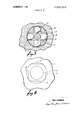
- FIG. 1 is a top plan view of a mill liner section showing an eye bolt assembly made according to the present I invention and installed therein.
- a removable locking and lifting bolt assembly shown generally at is mounted in a mill liner section 11, or some similar heavy object.
- the mill liners are mounted on the interior of heavy ball and roller mills, such as those used for grinding Taconite, and have to be replaced from time to time.
- One of the problems of course is getting secure fastening on the liner and still have a fastener that is removable so that it can be removed when the liner is in use in the mill.
- the bolt is used with a mill liner handler, such as that shown in U.S. Pat. application Ser. No. 69,529 filed Sept. 4, 1970 which is known to this applicant.
- the lifting device is described as an eye bolt herein, but it could be a stud or hook is desired.
- the locking bolt assembly as shown is fitted within an opening 12 that is formed in the mill liner section 11, when the liner section is cast, and the opening, as shown perhaps best in FIG. 4 is partial square, with rounded corners, with an interior annular ring or groove 13 located spaced down from the upper surface of the mill liner section.
- the corners of the square (rectilinear) opening are rounded as shown to the same size as the annular groove 13. Its maximum diagonal direction is defined by the diameter of the annular groove 13. This forms four groove portions 13, one aligned with each surface of the parallel sides of the rectilinear opening.
- the eye bolt assembly 10 comprises an outer housing 14 that as shown is the same cross sectional shape as the main opening 12 in the mill liner 11, and is a part square shanked housing having rounded corners to fit within the opening.
- the parallel sides of the housing are of size to slide within the parallel sides of the opening 12, and the maximum diagonal dimension is just slightly smaller thAn the diameter of the annular groove 13.
- the housing 14, as shown, has cross bores comprising openings 15 that are bored along axes at right angles to the parallel faces of the housing, and
- suitable lock balls 16 are mounted in these openings 15 so that there are four lock balls mounted in the housing.
- Small shoulder 17 are formed in each of the opening 15 to keep the balls from going inwardly beyond a certain position, and similar shoulders, or stop members may be used on the outer edge of opening 15 to keep the balls retained in the opening.
- the housing has a central axial bore or opening 19.
- the upper end of the housing is internally threaded as at 18, and the bore 19 extends downwardly and opens to the openings 15 for the balls 16.
- the balls 16 will project partially into bore 19 when the balls are back against shoulder 17.
- a lock bolt 21 has a threaded shank 22, and an axially extending pin portion 23 with a cam end 24.
- the bolt 21 is threadably mounted in the threads 18 and can be moved in and out between a solid line position as shown in FIG. 2 wherein the balls 16 are forced outwardly beyond the periphery of the housing 14, by the cam and pin to its dotted line position as shown in FIG. 2 wherein the balls can move inwardly along the cam portion 24 (which is an annular frusto-conical surface) partially retracted into the bore 19 so that the housing can be slid in and out of the opening 12.
- the device is made so that when the eye bolt assembly is to be removed from the millliner 11, the locking pin 21 is threaded outwardly to itS dotted line position so that the balls 16 can be moved inwardly, and then the outer periphery of the balls will clear the inner edges of the opening 12 and the housing and eye bolt assembly can be pulled outwardly easily.
- the housing When it is to be replaced, the housing is slid into place, and because of the square opening 12 and the matching configuration of the housing, the bolt can be screwed tightly without turning the housing to force the balls 16 outwardly into the groove portions 13 (there are four groove portions shown in FIG. 3) so that the balls are lockedpositively out by the pin portion 23 of the bolt.
- the bolt has an eye at its outer end, but this could be replaced by a hook, stud or the like.
- the housing 14 is of length so that it extends above the upper surface of the mill liner section when it is fully seated, and the under surface 25 of the eye bolt head will tighten down against the upper surface of the housing as the bolt is screwed tightly so that tight lock is obtained, and the locking or tightening is not dependent upon compression against the object to be lifted such as the mill liner section 11. This means that large levers can be used for tightening the locking device down securely so that it cannot come loose even through heavy loads may be utilized.
- annular groove portion 13 can be made with a fair amount of tolerance to it so that the opening in the mill liner can be cast in place without having expensive drilling or machining operations.
- the annular cam 24 operates about a center axis so that the load is transferred directly without putting a tensile load or bending load on the tapered cam portion 24.
- the cam can thus be made of a very hard material without regard to brittleness and it can be replaceable if desired.
- the entire cam pin can be replaced from the shank of the eye bolt.
- the device has a positive threaded lock that gives a good tight lock to prevent it from jiggling loose, working loose, or failing under load.
- the device is easy to manufacture and relatively low in cost while giving positive high load bearing capabilities.
- An attachable assembly used for lifting heavy objects comprising a heavy object, an opening defined in said object, said opening opening up to a first surface of said object, internal receptacle means defined in said object and extending to the interior surface defining said opening, said receptacle means being spaced from the outer surface of said object, a locking assembly fitting within said opening, said locking assembly comprising a housing, said housing having an axial passageway and a plurality of lock passageways, said lock passageways opening to the axial passageway and extending to the outer periphery of said housing and positioned to align with said receptacle means in said heavy object when said housing is seated therein, locking means movable in said lock passageways in said housing to a first position to partially enter said receptacle means and movable to a second position to clear said receptacle means, and a lifting member threadably mounted directly to said housing for threadable movement axially along said axial passageway including cam means positioned in said axial passageway to move said locking means outwardly
- said locking means comprises balls movable in said locking passageways into partial engagement with said receptacle eans, ands 'd lifti g memb r carg mean comprisesa rusto-conic cam ormmgt een o sai lifting member co-axial with the axis of said housing, acting on said balls to force said balls outwardly as said lifting member is threaded axially inward.
- said opening in said object comprises surfaces defining said opening which are oriented to have at least one surface portion positioned at a different radial distance from the axis of the opening than other surface portions.
Landscapes
- Engineering & Computer Science (AREA)
- Mechanical Engineering (AREA)
- Clamps And Clips (AREA)
- Load-Engaging Elements For Cranes (AREA)
Applications Claiming Priority (1)
| Application Number | Priority Date | Filing Date | Title |
|---|---|---|---|
| US7973170A | 1970-10-12 | 1970-10-12 |
Publications (1)
| Publication Number | Publication Date |
|---|---|
| US3680906A true US3680906A (en) | 1972-08-01 |
Family
ID=22152435
Family Applications (1)
| Application Number | Title | Priority Date | Filing Date |
|---|---|---|---|
| US79731A Expired - Lifetime US3680906A (en) | 1970-10-12 | 1970-10-12 | Removable eye bolt for lifting heavy objects |
Country Status (7)
| Country | Link |
|---|---|
| US (1) | US3680906A (show.php) |
| AU (1) | AU466228B2 (show.php) |
| CA (1) | CA958522A (show.php) |
| FR (1) | FR2110367B3 (show.php) |
| GB (1) | GB1358282A (show.php) |
| IT (1) | IT939521B (show.php) |
| SE (1) | SE376279B (show.php) |
Cited By (13)
| Publication number | Priority date | Publication date | Assignee | Title |
|---|---|---|---|---|
| US4204711A (en) * | 1978-07-20 | 1980-05-27 | Brown Company | Coupling for lift system for concrete slabs |
| US4699410A (en) * | 1986-08-28 | 1987-10-13 | Seidel Richard E | Swivel connector for hoists and the like |
| US4863205A (en) * | 1987-09-04 | 1989-09-05 | Jergens, Incorporated | Load ring assembly |
| US5775751A (en) * | 1997-08-29 | 1998-07-07 | Nelson; Ryan L. | Ball retrieval, storage and discharge device |
| US6478350B2 (en) | 2000-06-15 | 2002-11-12 | Shbl S.A. | Pivoting lifting ring |
| WO2008068365A1 (es) * | 2006-12-01 | 2008-06-12 | Habidite, S.A. | Útil de elevación para módulos prefabricados de viviendas |
| WO2009111835A1 (en) * | 2008-03-14 | 2009-09-17 | Brian Investments Pty Ltd | A device for lifting |
| US20140090206A1 (en) * | 2011-03-18 | 2014-04-03 | Commerical Industrial Maquinaria Carton Ondulado, S.L. | Handle for Handling Dies Rapidly and Safely |
| US10968509B2 (en) * | 2018-09-27 | 2021-04-06 | Shenzhen China Star Optoelectronics Semiconductor Display Technology Co., Ltd. | Picking assembly, crucible picking device, and method for picking crucible |
| US11097926B2 (en) * | 2013-07-10 | 2021-08-24 | Esco Group Llc | Connector to facilitate lifting of wear parts |
| US11111112B2 (en) * | 2016-09-15 | 2021-09-07 | Balltec Limited | Lifting assembly and method |
| NO20200353A1 (no) * | 2020-03-25 | 2021-09-27 | Hylestad Solutions As | Sjakkelboltlås og sjakkel omfattende sjakkelboltlåsen |
| DE202022105643U1 (de) | 2021-10-21 | 2022-11-04 | Industrias Piqueras Sa | Abnehmbarer Fixierungsbolzen |
Families Citing this family (2)
| Publication number | Priority date | Publication date | Assignee | Title |
|---|---|---|---|---|
| GB2551716B (en) | 2016-06-27 | 2019-02-06 | Balltec Ltd | A connector with locking elements releasable under load |
| CN111099498A (zh) * | 2019-12-09 | 2020-05-05 | 北京航星机器制造有限公司 | 一种3d打印砂芯的吊挂结构及吊挂方法 |
Citations (2)
| Publication number | Priority date | Publication date | Assignee | Title |
|---|---|---|---|---|
| FR999389A (show.php) * | 1952-01-31 | |||
| US3242666A (en) * | 1963-12-26 | 1966-03-29 | Carl R Peterson | Safe parachute pack opener with indicator |
-
1970
- 1970-10-12 US US79731A patent/US3680906A/en not_active Expired - Lifetime
-
1971
- 1971-10-01 AU AU34112/71A patent/AU466228B2/en not_active Expired
- 1971-10-01 GB GB4573871A patent/GB1358282A/en not_active Expired
- 1971-10-04 CA CA124,343A patent/CA958522A/en not_active Expired
- 1971-10-08 IT IT53360/71A patent/IT939521B/it active
- 1971-10-11 SE SE7112875A patent/SE376279B/xx unknown
- 1971-10-11 FR FR7136523A patent/FR2110367B3/fr not_active Expired
Patent Citations (2)
| Publication number | Priority date | Publication date | Assignee | Title |
|---|---|---|---|---|
| FR999389A (show.php) * | 1952-01-31 | |||
| US3242666A (en) * | 1963-12-26 | 1966-03-29 | Carl R Peterson | Safe parachute pack opener with indicator |
Cited By (16)
| Publication number | Priority date | Publication date | Assignee | Title |
|---|---|---|---|---|
| US4204711A (en) * | 1978-07-20 | 1980-05-27 | Brown Company | Coupling for lift system for concrete slabs |
| US4699410A (en) * | 1986-08-28 | 1987-10-13 | Seidel Richard E | Swivel connector for hoists and the like |
| US4863205A (en) * | 1987-09-04 | 1989-09-05 | Jergens, Incorporated | Load ring assembly |
| US5775751A (en) * | 1997-08-29 | 1998-07-07 | Nelson; Ryan L. | Ball retrieval, storage and discharge device |
| US6478350B2 (en) | 2000-06-15 | 2002-11-12 | Shbl S.A. | Pivoting lifting ring |
| WO2008068365A1 (es) * | 2006-12-01 | 2008-06-12 | Habidite, S.A. | Útil de elevación para módulos prefabricados de viviendas |
| US20100181790A1 (en) * | 2006-12-01 | 2010-07-22 | Habidite, S.A. | Lifting tool for prefabricated dwelling modules |
| WO2009111835A1 (en) * | 2008-03-14 | 2009-09-17 | Brian Investments Pty Ltd | A device for lifting |
| US20140090206A1 (en) * | 2011-03-18 | 2014-04-03 | Commerical Industrial Maquinaria Carton Ondulado, S.L. | Handle for Handling Dies Rapidly and Safely |
| US11097926B2 (en) * | 2013-07-10 | 2021-08-24 | Esco Group Llc | Connector to facilitate lifting of wear parts |
| US11111112B2 (en) * | 2016-09-15 | 2021-09-07 | Balltec Limited | Lifting assembly and method |
| US10968509B2 (en) * | 2018-09-27 | 2021-04-06 | Shenzhen China Star Optoelectronics Semiconductor Display Technology Co., Ltd. | Picking assembly, crucible picking device, and method for picking crucible |
| NO20200353A1 (no) * | 2020-03-25 | 2021-09-27 | Hylestad Solutions As | Sjakkelboltlås og sjakkel omfattende sjakkelboltlåsen |
| NO347055B1 (no) * | 2020-03-25 | 2023-05-02 | Hylestad Solutions As | Sjakkelboltlås og sjakkel omfattende sjakkelboltlåsen |
| US12215758B2 (en) | 2020-03-25 | 2025-02-04 | Hylestad Solutions As | Shackle lock and shackle comprising said shackle lock |
| DE202022105643U1 (de) | 2021-10-21 | 2022-11-04 | Industrias Piqueras Sa | Abnehmbarer Fixierungsbolzen |
Also Published As
| Publication number | Publication date |
|---|---|
| FR2110367B3 (show.php) | 1974-06-07 |
| SE376279B (show.php) | 1975-05-12 |
| AU3411271A (en) | 1973-04-05 |
| AU466228B2 (en) | 1975-10-23 |
| GB1358282A (en) | 1974-07-03 |
| CA958522A (en) | 1974-12-03 |
| IT939521B (it) | 1973-02-10 |
| FR2110367A3 (show.php) | 1972-06-02 |
Similar Documents
| Publication | Publication Date | Title |
|---|---|---|
| US3680906A (en) | Removable eye bolt for lifting heavy objects | |
| US4889458A (en) | Lock nut assemblies | |
| US3561516A (en) | Safety bolt | |
| US3765465A (en) | Retractable captive fastener | |
| US3042094A (en) | Locking screw with expanding means at each end | |
| US4079983A (en) | Weight lifting eye and socket | |
| US3726533A (en) | Spring biased coupling for tool and chuck | |
| US3817146A (en) | Bolt hole aligner and inserting tool | |
| US2571641A (en) | Quick release locking type shear load bearing fastener | |
| US2376089A (en) | Fastening device | |
| US4507034A (en) | Expandable bushing and lock fastener | |
| US9004833B1 (en) | Toggle bolt device | |
| US4969627A (en) | Rod locking device | |
| CN103241648B (zh) | 活塞销垂直起吊工装 | |
| EP0243463A1 (en) | LOCKING NUT AND METHOD FOR THEIR PRODUCTION. | |
| US4671718A (en) | Expanding latch captive bolt fastener | |
| US3267792A (en) | Torque limited hex nut | |
| DE3146991C2 (de) | Verschluß eines unter Druck stehenden Rohrquerschnitts | |
| US3425705A (en) | Collet chuck and the like | |
| US2892376A (en) | Split bolt radially expandable to size and locked by means of tapered core pin | |
| US2181103A (en) | Fastening means | |
| US3219371A (en) | Die post construction | |
| DE1138520B (de) | Stopfen fuer ein Giessgefaess mit Bodenauslassoeffnung | |
| US2448902A (en) | Nut lock construction | |
| US3023035A (en) | Hub mounting means |
Legal Events
| Date | Code | Title | Description |
|---|---|---|---|
| AS | Assignment |
Owner name: BANK OF NEW ENGLAND N.A. (AS AGENT) Free format text: SECURITY INTEREST;ASSIGNOR:GCA CORPORATION, A DE CORP;REEL/FRAME:004730/0239 Effective date: 19860228 |
|
| AS | Assignment |
Owner name: CIMCORP GCA CORPORATION'S, ILLINOIS Free format text: ASSIGNMENT OF ASSIGNORS INTEREST;ASSIGNOR:GCA CORPORATION, A DE. CORP.;REEL/FRAME:004643/0219 Effective date: 19860929 Owner name: CIMCORP GCA CORPORATION'S, 615 NORTH ENTERPRISE AV Free format text: ASSIGNMENT OF ASSIGNORS INTEREST.;ASSIGNOR:GCA CORPORATION, A DE. CORP.;REEL/FRAME:004643/0219 Effective date: 19860929 |