US3675111A - Automatic dc voltage regulating system - Google Patents
Automatic dc voltage regulating system Download PDFInfo
- Publication number
- US3675111A US3675111A US152049A US3675111DA US3675111A US 3675111 A US3675111 A US 3675111A US 152049 A US152049 A US 152049A US 3675111D A US3675111D A US 3675111DA US 3675111 A US3675111 A US 3675111A
- Authority
- US
- United States
- Prior art keywords
- voltage
- automatic
- voltage regulating
- output
- regulating system
- Prior art date
- Legal status (The legal status is an assumption and is not a legal conclusion. Google has not performed a legal analysis and makes no representation as to the accuracy of the status listed.)
- Expired - Lifetime
Links
- 230000001105 regulatory effect Effects 0.000 title claims abstract description 57
- 238000004804 winding Methods 0.000 claims abstract description 41
- 239000003990 capacitor Substances 0.000 claims abstract description 30
- 230000001939 inductive effect Effects 0.000 claims abstract description 5
- 238000009499 grossing Methods 0.000 claims description 12
- XEEYBQQBJWHFJM-UHFFFAOYSA-N Iron Chemical group [Fe] XEEYBQQBJWHFJM-UHFFFAOYSA-N 0.000 claims description 11
- 230000005279 excitation period Effects 0.000 claims description 8
- 230000008859 change Effects 0.000 claims description 5
- 230000001276 controlling effect Effects 0.000 abstract description 3
- 238000010586 diagram Methods 0.000 description 11
- 229920006395 saturated elastomer Polymers 0.000 description 10
- 230000008901 benefit Effects 0.000 description 4
- 230000007423 decrease Effects 0.000 description 3
- 230000005284 excitation Effects 0.000 description 3
- 230000010363 phase shift Effects 0.000 description 3
- 230000007547 defect Effects 0.000 description 2
- 230000004907 flux Effects 0.000 description 2
- 241001315609 Pittosporum crassifolium Species 0.000 description 1
- 230000033228 biological regulation Effects 0.000 description 1
- 238000005352 clarification Methods 0.000 description 1
- 230000003247 decreasing effect Effects 0.000 description 1
- 230000000694 effects Effects 0.000 description 1
- 238000002474 experimental method Methods 0.000 description 1
- 230000004048 modification Effects 0.000 description 1
- 238000012986 modification Methods 0.000 description 1
- 230000010349 pulsation Effects 0.000 description 1
- QHGVXILFMXYDRS-UHFFFAOYSA-N pyraclofos Chemical compound C1=C(OP(=O)(OCC)SCCC)C=NN1C1=CC=C(Cl)C=C1 QHGVXILFMXYDRS-UHFFFAOYSA-N 0.000 description 1
- 230000009467 reduction Effects 0.000 description 1
- 230000004044 response Effects 0.000 description 1
- 238000006467 substitution reaction Methods 0.000 description 1
Images


Classifications
-
- H—ELECTRICITY
- H02—GENERATION; CONVERSION OR DISTRIBUTION OF ELECTRIC POWER
- H02M—APPARATUS FOR CONVERSION BETWEEN AC AND AC, BETWEEN AC AND DC, OR BETWEEN DC AND DC, AND FOR USE WITH MAINS OR SIMILAR POWER SUPPLY SYSTEMS; CONVERSION OF DC OR AC INPUT POWER INTO SURGE OUTPUT POWER; CONTROL OR REGULATION THEREOF
- H02M7/00—Conversion of AC power input into DC power output; Conversion of DC power input into AC power output
- H02M7/02—Conversion of AC power input into DC power output without possibility of reversal
- H02M7/04—Conversion of AC power input into DC power output without possibility of reversal by static converters
- H02M7/12—Conversion of AC power input into DC power output without possibility of reversal by static converters using discharge tubes with control electrode or semiconductor devices with control electrode
- H02M7/145—Conversion of AC power input into DC power output without possibility of reversal by static converters using discharge tubes with control electrode or semiconductor devices with control electrode using devices of a thyratron or thyristor type requiring extinguishing means
- H02M7/155—Conversion of AC power input into DC power output without possibility of reversal by static converters using discharge tubes with control electrode or semiconductor devices with control electrode using devices of a thyratron or thyristor type requiring extinguishing means using semiconductor devices only
- H02M7/1555—Conversion of AC power input into DC power output without possibility of reversal by static converters using discharge tubes with control electrode or semiconductor devices with control electrode using devices of a thyratron or thyristor type requiring extinguishing means using semiconductor devices only with control circuit
- H02M7/1557—Conversion of AC power input into DC power output without possibility of reversal by static converters using discharge tubes with control electrode or semiconductor devices with control electrode using devices of a thyratron or thyristor type requiring extinguishing means using semiconductor devices only with control circuit with automatic control of the output voltage or current
Definitions
- An automatic DC voltage regulating system includes an automatic AC voltage regulator whose output impedance is inductive. Voltages respectively in phase with the voltages of an input and an output winding of this AC voltage regulator are combined by means of a pair of additional windings magnetically connected with the input and output windings and themselves interconnected in series.
- a series circuit of a resistance and a capacitor for example, is connected to the aforesaid additional windings so as to cause a desired phase lag to the above obtained resultant of the input and output voltages of the AC voltage regulator.
- the output voltage of this resistance-capacitor series circuit is applied via a transformer to a rectifier connected in tandem with the AC voltage regulator,
- This invention relates generally to voltage regulating systems, and in particular to improved automatic DC voltage regulating systems of a type where the output of an automatic AC voltage regulator is rectified for the provision of DC power.
- the above scheme (1) permits easy and precise voltage regulation, making possible to produce DC voltage with a minimized degree of fluctuations, but has a drawback in that it necessitates highly involved circuit configurations.
- the operation of the systems based upon this scheme is not reliable enough under unfavorable atmospheric conditions such as high temperature and humidity.
- the scheme (2) may be well suited for large-capacity DC power supply, a smoothing circuit employed for the removal of fluctuations in the DC output tends to cause the socalled hunting and may retard the response speed of the system.
- the scheme (3) has its inherent drawback, too, in that the DC voltage obtained is subject to fluctuations along with load fluctuations. This hitherto unremedied defect nearly offsets its greatest advantage, i.e. a simple and high-reliability voltage regulating system realized thereby.
- the present invention has it as a primary object to provide a new and better automatic DC voltage regulating system of simple circuit configuration, whereby constant DC power is obtainable from AC sources under varying load conditions.
- Another object of the invention is to provide an automatic DC voltage regulating system wherein the variations of a phase difference between the input and output voltages of an automatic AC voltage regulator in use are utilized for the supply of greatly stabilized DC voltage.
- Still another object of the invention is to provide an automatic DC voltage regulating system wherein a rectifier is connected so as to be capable of automatically compensating for voltage drop that may be caused by the internal resistance of a DC output circuit and by a capacitor used in a smoothing circuit.
- Yet another object of the invention is to provide an automatic DC voltage regulating system wherein a phase shift circuit is provided to cause some phase lag to the resultant of the input and output voltages of an automatic AC voltage regulator in use, a phase difference between these input and output voltages being subject to change in proportion to the value of the load current of the automatic AC voltage regulator, and the output voltage of the aforesaid phase shift circuit with its phase lag is applied as a gate signal to a rectifier (connected in tandem with the automatic AC voltage regulator) for voltage control in accordance with load fluctuations.
- FIG. 1 is a connection diagram of a prior automatic DC voltage regulating system
- FIGS. 2(a) and (b) are vector diagrams given by way of explanation of the operation of the prior automatic DC voltage regulating system of FIG. 1;
- FIG. 3(a) is a connection diagram of an embodiment of the present invention making use of a constant voltage regulator, FIG. 3(b) being a connection diagram showing a modified example of the circuit portion of FIG. 3(a) surrounded by the dotted lines;
- FIG. 4 is an equivalent circuit diagram of the automatic DC voltage regulating system of FIG. 3(a);
- FIG. 5 is a vector diagram given by way of explanation of the operation of the automatic DC voltage regulating system of FIGS. 3 and 4;
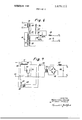
- FIG. 6 is a connection diagram of another embodiment of the present invention.
- FIG. 7 is a connection diagram of still another embodiment of the present invention.
- FIG. 1 of the appended drawings schematically illustrates the circuit configuration of the prior automatic DC voltage regulating system
- FIGS. 2(a) and (b) are vectorial representations of the voltages indicated during the operation of this prior system.
- the reference character F generally designates an automatic AC voltage regulator, equipped with a ferroresonant circuit comprising a heavily saturated reactor 1 and a capacitor 2 connected in parallel therewith. This ferroresonant circuit is connected to AC power supply terminals T, and T, via an unsaturated reactor 3.
- An output winding 4 is wound on the heavily saturated reactor 1, while being insulated therefrom, and its alternating output voltage is to be converted into DC voltage by means of a full-wave rectifier 5 with its four diodes D interconnected in the form of a bridge circuit.
- This DC voltage is to be obtained from DC output terminals T and T, upon removal of its fluctuations by means of a smoothing circuit 8 comprising a choke 6 and a capacitor 7.
- E be the AC voltage applied to the terminals T, and T,', and E, be the terminal voltage of the heavily saturated reactor 1.
- the terminal voltage E, of the unsaturated reactor 3 will be detemtined by load current due to the output winding 4 and, if this load current is due to resistance, the voltage E, will be in rectangular phase relationship with the voltage E, as illustrated in FIG. 2(a). Since E, E, E,, this input voltage E, may be vectorially represented by the line connecting the base 0 of the vector E, and the arrow-headed end of the vector E as in FIG. 2(a).
- FIG. 3(a) schematically illustrates an exemplary configuration of an automatic DC voltage regulating system in accordance with the present invention
- the reference numeral generally designates an automatic ferroresonant voltage regulator with a single iron core, or the socalled constant voltage transfonner (hereinafter referred to by this latter term).
- the iron core provided to this constant voltage transformer 10 includes a portion 11 for a path of leakage flux.
- a ferroresonance winding 15 which is parallel connected with a capacitor 14. Further on this secondary side iron core portion 12b there is wound an output winding 16 which is magnetically connected with the aforesaid ferroresonance winding 15. The both ends of this output winding 16 are connected to a pair of the junctions of a full-wave rectifier 17 in which are connected two diodes D, and D and two thyristors SCR, and SCR, in the form of a bridge circuit.
- the other pair of the junctions of this full-wave rectifier 17 are connected to a smoothing circuit comprising a choke l8 and a capacitor 19, thereby to remove fluctuations in the DC output voltage of the full-wave rectifier l7 and to produce the desired constant DC voltage from output terminals T and T
- Additional windings 20 and 21 coiled on the aforesaid primary and secondary side portions 124 and 12b, respectively, of the iron core are interconnected in series so that their voltages may be added together.
- the functions of the constant voltage transformer 10 are substantially as described already with respect to the automatic AC voltage regulator of FIG. 1.
- the iron core portion including the ferroresonance winding 15 is heavily saturated, and this winding 15 in combination with the capacitor 14 causes the ferroresonant phenomenon.
- the portion 11 as a path of leakage flux functions the same as the unsaturated reactor of FIG. 1.
- FIG. 4 is an equivalent representation of the overall circuit of FIG. 3(a).
- this equivalently converted circuit of FIG. 4 if the thyristors SCR, and SCR, of the fullwave rectifier 17 are kept excited with the aforesaid gate control signals from the transformer 24, this rectifier will function the same as an ordinary rectifier. Consequently this circuit operates in a manner corresponding to the operation of the above described circuit of FIG. 1, producing constant DC voltage regardless of fluctuations in AC voltage supplied.
- the terminal voltage E 23 of the capacitor 23 has a phase lag equal to ⁇ II, determined by the capacitor 23 itself and the resistance 22, with respect to the aforesaid resultant voltage 5,, B Hence the phase angle between E, and E is: n11 I This angle is to decrease along with increase in the angle 0 between the input voltage vector E, and the AC output voltage vector E, due to increase in the value of the load current, and vice versa.
- the values of the resistance 22 and the capacitor 23 are so determined that the vector E at full load may approximate the vector E, in phase. Accordingly, when the value of the load current increases, the voltage impressed to the respective gates of the thyristors SCR, and SCR, approximates the voltage E, in phase, thus resulting in increased DC output voltage, whereas, when the value of the load current decreases, the excitation periods of the thyristors SCR, and SCR, are retarded, which results in decreased DC output voltage. It is also proposed herewith that, by adequate selection of the ratio between E, and B a tendency of DC output fluctuations due to load fluctuations and a tendency of voltage fluctuations due to the rectifier, the smoothing circuit, etc. in use are directed opposite to each other and hence are counterbalanced. The fluctuations in the DC output voltage due to load fluctuations are thus remarkably reduced. A superior DC power supply is hereby materialized whose output does not fluctuate to any appreciable degree regardless of variations not only of the input voltage but of the load current, too. I
- the value of 15, may be made large compared to that of E, to reduce variations of 1 when the internal resistance of the full-wave rectifier and the smoothing circuit in use are small.
- the value of E may be reduced or it may be opposite phased as desired, thereby to increase the variations of I
- the transformer 24 is used in order to obtain opposite-phased voltages for the excitation of the two thyristors SCR, and SCR, in this particular embodiment, will be understood that the portion of the circuit of FIG. 3(a) surrounded by the dotted lines may be rearranged as in FIG.
- constant voltage transformer 10 mentioned as an automatic AC voltage regulator in the same embodiment is not of a lirnitative nature; indeed, it may be replaced by any other automatic AC voltage regulator only if its output impedance is inductive, such that the phase of its output voltage increases in the lagging direction with respect to the input voltage when the load current increases.
- FIG. 6 The circuit configuration of another embodiment of the present invention is schematically illustrated in FIG. 6, where circuit elements used likewise in FIG. 3(a) or 4 are indicated by like reference characters.
- a center-tapped output winding is for single-phase full-wave rectification, thyristors SCR and SCR being connected to the terminals of this output winding 25.
- thyristors SCR and SCR are also connected to windings 20 and 21, respectively, which are adapted to obtain voltages in phase with the voltages of a primary 13 and a secondary 15.
- phase shift circuit As a phase shift circuit (or a fixed phase lag circuit, to be more specific) connected in series with these windings 20 and 21, there is provided a series circuit of an inductance 26, a resistance 27 and another resistance 28.
- the terminal voltage of these resistances 27 and 28 is to be impressed to the respective gates of the aforesaid thyristors SCR, and SCR
- the phase of the voltage obtained from the terminals of the resistances 27 and 28 comes near to the phase of the AC output voltage of the constant voltage transformer 10 when the load current is comparatively large, and lags the phase of the AC output voltage when the load current is comparatively small, thus controlling the excitation periods of the thyristors SCR and SCR and accordingly modifying the fluctuations in the DC output voltage obtained.
- the aforesaid inductance 26 of this circuit may be replaced by a saturable reactor, thereby to render variable the value of the fixed phase lag by adjustment of its direct exciting current.
- This alternative has the advantage of permitting the fine adjustment of the DC output voltage, either automatically or manually.
- FIG. 7 schematically illustrates the circuit configuration of still another embodiment of the present invention, wherein an automatic AC voltage regulator F is of popular ferroresonance type, comprising an inductance 29, a saturated reactor 30 and a capacitor 31.
- the reference numeral 32 indicates a thyristor for altemating current, 33 a transformer for the supply of AC voltage to a rectifier 34, and 35 a choke which in combination with a capacitor 36 constitutes a smoothing circuit.
- a resistance 37 and a capacitor 38 are designed to cause the above explained fixed phase lag, while an insulating transformer 39 is provided for applying the lagging voltage obtained to the gate of the aforesaid thyristor 32.
- the voltage obtained from between a tap 40 provided to the inductance 29 and an input terminal 41 is in such phase relationship with the AC output voltage of the automatic AC voltage regulator F as explained already, so that the DC output voltage obtained similarly increases along with increase in the value of the load current.
- the above voltage is supplied to the gate of the thyristor 32 via a phase shifl circuit (consisting of the resistance 37 and the capacitor 38) and the insulating transformer 39. Also as explained already, the excitation periods of the thyristor 32 are then caused to quicken upon increase in the value of the load current, so that the AC voltage applied to the transformer 33 increases. When the value of the load current decreases, the excitation periods of the thyristor 32 tend to retard. It is accordingly possible to ing s tem.
- An automatic DC voltage regulating system comprising, in combination:
- a rectifying means connected in tandem with said automatic AC voltage regulating means and comprising a plurality of rectifying elements at least one of which is a thyristor;
- a voltage combining means for obtaining the resultant of the input voltage and output voltage of said automatic AC voltage regulating means, a phase lag of said output volt age with respect to said input voltage being subject to change along with variation in the value of the load current of said automatic AC voltage regulating means;
- phase shifting means connected between said voltage combining means and said rectifying means, said phase shifting means causing such a phase lag to the output voltage of said voltage combining means that said output voltage of said voltage combining means becomes substantially in phase with said output voltage of said automatic AC voltage regulating means only at full load;
- phase shifting means is formed by a series circuit of a resistance and a capacitor.
- phase shifting means is formed by a series circuit of a resistance and two capacitors.
- phase shifting means is formed by a series circuit of an inductance and two resistances.
- phase shifting means comprises a resistive element and a capacitor
- an insulating transformer is connected between said phase shifting means and the gate of said at least one thyristor included in said rectifying means.
- said voltage combining means comprises a pair of windings coiled on an iron core of said automatic AC voltage regulating means so as to be respectively magnetically connected with an input winding and output winding thereof, said pair of windings being interconnected in series so as to provide the resultant of voltages respectively in phase with the compensate for the fluctuations that may otherwise be present mlmges of Said input windmg and said Output winding in the DC output voltage of this automatic DC voltage regulat-
Landscapes
- Engineering & Computer Science (AREA)
- Power Engineering (AREA)
- Control Of Electrical Variables (AREA)
- Rectifiers (AREA)
Applications Claiming Priority (1)
| Application Number | Priority Date | Filing Date | Title |
|---|---|---|---|
| JP45055721A JPS5029131B1 (ja) | 1970-06-25 | 1970-06-25 |
Publications (1)
| Publication Number | Publication Date |
|---|---|
| US3675111A true US3675111A (en) | 1972-07-04 |
Family
ID=13006716
Family Applications (1)
| Application Number | Title | Priority Date | Filing Date |
|---|---|---|---|
| US152049A Expired - Lifetime US3675111A (en) | 1970-06-25 | 1971-06-11 | Automatic dc voltage regulating system |
Country Status (2)
| Country | Link |
|---|---|
| US (1) | US3675111A (ja) |
| JP (1) | JPS5029131B1 (ja) |
Cited By (2)
| Publication number | Priority date | Publication date | Assignee | Title |
|---|---|---|---|---|
| US3772586A (en) * | 1972-10-12 | 1973-11-13 | Zyrotron Ind Inc | Firing circuit and transformer |
| US6549438B2 (en) | 2001-04-30 | 2003-04-15 | Precision Automation, Inc. | AC-to-DC converter circuit utilizing IGBT's for improved efficiency |
Citations (4)
| Publication number | Priority date | Publication date | Assignee | Title |
|---|---|---|---|---|
| US3129383A (en) * | 1959-11-14 | 1964-04-14 | Karo David | Voltage stabilizing electrical transformers |
| US3205425A (en) * | 1962-01-08 | 1965-09-07 | Eltra Corp | Voltage stabilized converter devices |
| US3223922A (en) * | 1960-08-29 | 1965-12-14 | Borg Warner | Voltage regulator circuit |
| US3358210A (en) * | 1964-06-25 | 1967-12-12 | Gen Electric | Voltage regulator |
-
1970
- 1970-06-25 JP JP45055721A patent/JPS5029131B1/ja active Pending
-
1971
- 1971-06-11 US US152049A patent/US3675111A/en not_active Expired - Lifetime
Patent Citations (4)
| Publication number | Priority date | Publication date | Assignee | Title |
|---|---|---|---|---|
| US3129383A (en) * | 1959-11-14 | 1964-04-14 | Karo David | Voltage stabilizing electrical transformers |
| US3223922A (en) * | 1960-08-29 | 1965-12-14 | Borg Warner | Voltage regulator circuit |
| US3205425A (en) * | 1962-01-08 | 1965-09-07 | Eltra Corp | Voltage stabilized converter devices |
| US3358210A (en) * | 1964-06-25 | 1967-12-12 | Gen Electric | Voltage regulator |
Cited By (2)
| Publication number | Priority date | Publication date | Assignee | Title |
|---|---|---|---|---|
| US3772586A (en) * | 1972-10-12 | 1973-11-13 | Zyrotron Ind Inc | Firing circuit and transformer |
| US6549438B2 (en) | 2001-04-30 | 2003-04-15 | Precision Automation, Inc. | AC-to-DC converter circuit utilizing IGBT's for improved efficiency |
Also Published As
| Publication number | Publication date |
|---|---|
| JPS5029131B1 (ja) | 1975-09-20 |
Similar Documents
| Publication | Publication Date | Title |
|---|---|---|
| US2306998A (en) | Automatic voltage and current regulating device | |
| US2278151A (en) | Regulating apparatus | |
| US2723372A (en) | System utilizing current limit device providing line drop compensation | |
| US3253212A (en) | Ferro-resonant control elements and variable voltage power source incorporating same | |
| US2399185A (en) | Regulating apparatus | |
| US3042848A (en) | Voltage regulator | |
| US2710938A (en) | Regulated rectifier power supply system | |
| US2547615A (en) | Saturable core reactor | |
| US2911586A (en) | Electric control signal deriving system | |
| US3675111A (en) | Automatic dc voltage regulating system | |
| US2722654A (en) | Regulating system utilizing a saturable reactor having negative feedback | |
| US2057490A (en) | Regulating system | |
| US3233165A (en) | Voltage regulator with rectifier and phase controlled scr inverter | |
| US2040684A (en) | Electric circuit control means | |
| US2802166A (en) | Regulators | |
| US2992379A (en) | Power supply having an extended regulation range | |
| US3045170A (en) | Regulated rectifier | |
| US3614595A (en) | Ac voltage control apparatus | |
| US2092859A (en) | Electrical regulating apparatus for rectifiers | |
| US2916685A (en) | Direct current motor speed control system | |
| US2724797A (en) | Stabilizing circuit for alternating current generator | |
| US3037160A (en) | Magnetically regulated power supply | |
| US3088065A (en) | Self-regulated static frequency converter | |
| US3611116A (en) | Ferroresonant voltage regulator with saturable and unsaturable transformers | |
| US2777987A (en) | Voltage regulator compensating voltage and frequency changes |