US3673489A - Alternator and regulator control system - Google Patents

Alternator and regulator control system Download PDF

Info

Publication number
US3673489A
US3673489A US169431A US3673489DA US3673489A US 3673489 A US3673489 A US 3673489A US 169431 A US169431 A US 169431A US 3673489D A US3673489D A US 3673489DA US 3673489 A US3673489 A US 3673489A
Authority
US
United States
Prior art keywords
winding
alternator
voltage
output
control system
Prior art date
Legal status (The legal status is an assumption and is not a legal conclusion. Google has not performed a legal analysis and makes no representation as to the accuracy of the status listed.)
Expired - Lifetime
Application number
US169431A
Inventor
James A Riff
Current Assignee (The listed assignees may be inaccurate. Google has not performed a legal analysis and makes no representation or warranty as to the accuracy of the list.)
Prestolite Electric Inc
Original Assignee
Motorola Inc
Priority date (The priority date is an assumption and is not a legal conclusion. Google has not performed a legal analysis and makes no representation as to the accuracy of the date listed.)
Filing date
Publication date
Application filed by Motorola Inc filed Critical Motorola Inc
Application granted granted Critical
Publication of US3673489A publication Critical patent/US3673489A/en
Assigned to PRESTOLITE ELECTRIC INCORPORATED, FOUR SEAGATE, TOLEDO, OHIO, A CORP. OF DE reassignment PRESTOLITE ELECTRIC INCORPORATED, FOUR SEAGATE, TOLEDO, OHIO, A CORP. OF DE ASSIGNMENT OF ASSIGNORS INTEREST. Assignors: MOTOROLA, INC.
Anticipated expiration legal-status Critical
Assigned to PEI 1991 ACQUISITION, INC. reassignment PEI 1991 ACQUISITION, INC. ASSIGNMENT OF ASSIGNORS INTEREST. Assignors: PRESTOLITE ELECTRIC INCORPORATED
Expired - Lifetime legal-status Critical Current

Links

Images

Classifications

    • HELECTRICITY
    • H02GENERATION; CONVERSION OR DISTRIBUTION OF ELECTRIC POWER
    • H02PCONTROL OR REGULATION OF ELECTRIC MOTORS, ELECTRIC GENERATORS OR DYNAMO-ELECTRIC CONVERTERS; CONTROLLING TRANSFORMERS, REACTORS OR CHOKE COILS
    • H02P9/00Arrangements for controlling electric generators for the purpose of obtaining a desired output
    • H02P9/14Arrangements for controlling electric generators for the purpose of obtaining a desired output by variation of field
    • H02P9/26Arrangements for controlling electric generators for the purpose of obtaining a desired output by variation of field using discharge tubes or semiconductor devices
    • H02P9/30Arrangements for controlling electric generators for the purpose of obtaining a desired output by variation of field using discharge tubes or semiconductor devices using semiconductor devices
    • HELECTRICITY
    • H02GENERATION; CONVERSION OR DISTRIBUTION OF ELECTRIC POWER
    • H02JCIRCUIT ARRANGEMENTS OR SYSTEMS FOR SUPPLYING OR DISTRIBUTING ELECTRIC POWER; SYSTEMS FOR STORING ELECTRIC ENERGY
    • H02J7/00Circuit arrangements for charging or depolarising batteries or for supplying loads from batteries
    • H02J7/14Circuit arrangements for charging or depolarising batteries or for supplying loads from batteries for charging batteries from dynamo-electric generators driven at varying speed, e.g. on vehicle
    • H02J7/16Regulation of the charging current or voltage by variation of field
    • H02J7/24Regulation of the charging current or voltage by variation of field using discharge tubes or semiconductor devices
    • H02J7/2437Regulation of the charging current or voltage by variation of field using discharge tubes or semiconductor devices using thyristors or triacs as final control devices
    • YGENERAL TAGGING OF NEW TECHNOLOGICAL DEVELOPMENTS; GENERAL TAGGING OF CROSS-SECTIONAL TECHNOLOGIES SPANNING OVER SEVERAL SECTIONS OF THE IPC; TECHNICAL SUBJECTS COVERED BY FORMER USPC CROSS-REFERENCE ART COLLECTIONS [XRACs] AND DIGESTS
    • Y02TECHNOLOGIES OR APPLICATIONS FOR MITIGATION OR ADAPTATION AGAINST CLIMATE CHANGE
    • Y02TCLIMATE CHANGE MITIGATION TECHNOLOGIES RELATED TO TRANSPORTATION
    • Y02T10/00Road transport of goods or passengers
    • Y02T10/80Technologies aiming to reduce greenhouse gasses emissions common to all road transportation technologies
    • Y02T10/92Energy efficient charging or discharging systems for batteries, ultracapacitors, supercapacitors or double-layer capacitors specially adapted for vehicles

Definitions

  • An alternator and regulator control system includes diodes connected to the output windings of the alternator to pass unidirectional current pulses and to cause blocking of current when voltage in the output winding reverse biases the diodes.
  • This blockage of current produces a high reverse voltage pulse in the output winding which is then delivered to the field winding of the alternator through electronic switch means to cause excitation of the alternator to develop high power output in the stator windings of the alternator.
  • the electronic switch is a thyristor and forms part of a feedback circuit which is controlled by a voltage regulator that controls the output voltage of the alternator.
  • This invention relates generally to dynamoelectric machines and more particularly to an alternator and regulator control circuit of the type used in automotive electrical systems.
  • Alternators used in the electrical charging systems of automobiles are well known in the art and have always been considered a very efficient machine for charging the automobile battery and operating various electrical equipment as compared to the old DC generator type of system.
  • the alternator produces an alternating current voltage at the output thereof which is rectified through a plurality of diodes, generally in a full wave configuration, to provide the necessary DC voltage to the electrical components and battery charging system of the automobile.
  • the alternator system is considered superior to the DC generator in that charging current is obtained even when the engine is running at slow speed.
  • the alternator charging system is considered relatively efiicient, it has nevertheless some energy losses as a result of rapid turn off of diode rectifiers at the output.
  • the rapid turn ofi the diodes causes a high reverse voltage pulse to be developed at the output winding of the alternator as a result of the reduced current in the reverse direction of the diodes.
  • the rotating field of the alternator is excited by a DC current from the battery or alternator output, which is generally controlled by means of a voltage regulator. While this is a relatively common and straight forward method of exciting the rotating field of the alternator it requires external power to initiate start up operation of the alternator because of the relatively low levels of residual magnetism retained in the alternator components. This can be overcome by initially operating the alternator at high speeds. However, in some cases in the prior art small permanent magnets are put into the alternator to provide the magnetic field necessary for self start up of. the alternator. Also, the power output level of prior art alternators is substantially constant over a given range of engine speed and load.
  • a typical output may be about 40 amperes when the field is excited by the battery source and with an armature speed of between about 2,000 and 8,000 rpm.
  • This example is with a full wave rectifier arrangement at the output of the alternator.
  • the output is provided with a half wave rectifier arrangement, the output of the alternator will be increased at the higher rpm's but reduced at the lower rpm's.
  • the power output of the alternator is substantially limited for a given machine design and construction.
  • Yet another object of this invention is to provide an alternator and regulator control system wherein the excitation for the field is obtained by the reverse voltage pulses which occur upon turnoff of the output diodes of the alternator system.
  • Still another object of this invention is to provide an improved alternator and regulator control system which allows an alternator to operate more efficiently by utilizing the reverse voltage pulses generated inherently in the machine to energize the rotating field thereof.
  • the alternator and regulator control system includes the output windings of an alternator structure which are connected in WYE configuration.
  • the field winding of the alternator is arranged to receive pulses of direct current to develop a magnetic field which, in turn, generates the output of the alternator.
  • the pulses of direct current are converted either through a full wave bridge rectifier or half wave rectifier through a thyristor such as silicon controlled rectifier or other device in response to a switching circuit which controls the passage of high reverse voltage pulses developed as a result of rapid turn off of the output diodes. This high reverse voltage condition occurs each time current ceases to flow through a given output winding by reverse biasing of the associated diode.
  • the feedback of the high reverse voltage pulses to the field winding is obtained through a switching circuit controlled in response to a voltage regulator.
  • the high reverse voltage pulses are many times greater in voltage value than is obtained by the battery charging system at the alternator output that it induced a much higher voltage into the rotating field. This increased voltage, which is obtained from within the alternator itself, will greatly increase the output of the alternator far beyond that which can be obtained by present conventional methods.
  • the switching circuit which may form part of the voltage regulator will operate in the conventional manner but will switch the high reverse voltage pulses rather than the conventional battery voltage. For example, when the switching circuit is in the open condition, no feedback of high reverse voltage pulses occurs and the output of the alternator is reduced.
  • FIG. 1 is a schematic diagram of one form of alternator and regulator control system of this invention wherein a rotary transformer is associated with the alternator;
  • FIG. 2 is a voltage regulator which can be used in the circuit of FIG. 1;
  • FIG. 3 is a series of waveforms which represent the output of the alternator and regulator control system of FIG. 1;
  • FIG. 4 is an alternate form of alternator and regulator control system constructed in accordance with this invention.
  • FIG. 5 illustrates the several power curves obtained both from full wave and half wave alternator outputs of conventional design and also shows the marked improvement of alternator output when using the high reverse voltage pulses in accordance with this invention.
  • FIG. I there is seen an alternator and regulator control system designated generally by reference numeral 10.
  • the alternator is illustrated as having an output winding 12, which is generally the stator of the alternator, and a rotating field winding 14.
  • the field winding 14 is energized to provide a magnetic field which, in turn, induces an alternating current voltage in the output windings 12.
  • the output windings 12 are connected in WYE configuration with windings 12a, 12b and 12c connected together at a common circuit point 13 which, in turn, is here illustrated at the positive output terminal of the system.
  • Output diodes 16a, 16b and 16c are connected to the windings 12a, 12b and 120, respectively, to rectify the alternating current voltage induced in these windings to produce a direct current voltage across the output terminals 18 and 20. It will be noted that this is three phase half wave rectification where only three diodes are used rather than the usual six diode full wave configuration. When the cathode electrodes of diodes 16a, 16b and 160 are negative the alternating current voltage is delivered to terminals 18 and 20 in the form of pulsating DC. However, at the end of each negative half cycle, the diodes are instantly rendered nonconductive in the usual manner.
  • FIG. 3 illustrates the half wave pulses 22 which occur at the output of winding 12b, and the half wave pulses 24 which occur at the output winding-12c.
  • I-Ialf wave pulses 26 which occur at the output winding 12a are also illustrated, but the reverse voltage pulses that are produced by these pulses are not used for field excitation.
  • a broken line indicates the high voltage short time duration reverse voltage kickback pulse 22a, 24a and 26a for the associated pulses 22, 24 and 26, respectively.
  • Pulses 22b and 24b correspond to the reverse voltage pulses and are delivered to a rotary transformer 32 at each end thereof from windings 12b and 12c in time relation so that current passes alternately in one direction and then in the other direction through the primary winding 32a. Also, since the reverse pulses are obtained from across two windings 12b and 12c the net voltage is twice that otherwise obtained and the small amount of residual magnetism remaining in the system is then sufficient to initiate operation of the alternator.
  • the primary winding 32a is connected to a voltage regulator 40 to have the circuit thereof open and close in response to a switching mechanism indicated by 42 connected between the lines 44 and 46.
  • a switching mechanism indicated by 42 connected between the lines 44 and 46.
  • switch 42 When the switch 42 is open, no current passes through the primary winding 32a and no pulses are trans former coupled across the rotary transformer 32. However, upon sensing the output voltage at terminals 18 and 20, this being accomplished over lines 48 and 50, switch 42 closes and pulses of current then pass through the primary winding. Pulses of current which are transformer coupled into the rotary secondary winding 32b are rectified to produce a DC voltage by a plurality of diodes 33 which form the bridge rectifier circuit 34.
  • the output of the bridge circuit 34 is filtered by a capacitor 36 and applied to the field winding 14 as a DC or a pulsating DC current.
  • the rotary secondary winding 32b, the bridge circuit 34, and capacitor 36 and field winding 14 are all mounted on a common shaft for rotation therewith thus eliminating the need for brushes or other mechanical connections to the field winding.
  • the voltage regulator 40 may take any convenient form, which will sense variations in output voltage across terminals 18 and 20 and operatively energize and tie-energize the switching device 42.
  • the switching device 42 may be any relatively fast acting electronically or electrically controlled switching device.
  • a voltage regulator switching circuit 40A illustrates one such form of voltage regulator which can be used in the circuit of FIG. 1.
  • the regulator 40A has input lines 48a and 50a corresponding to lines 48 and 50 of FIG. 1 for receiving the energizing voltage.
  • a reverse bias protection diode 51 is connected across these lines and a voltage divider network including resistors 52 and 53 together with a thermistor S4 and capacitor 56 form the basic temperature compensation network for the regulator circuit. Variations in ambient temperature are thus compensated by changes in resistance value of the thermistor S4.
  • the center tap 55 of the voltage divider network is then applied to the base electrode of a transistor 57 through a zener diode 58 which provides a reference voltage for regulation.
  • a control current is developed across a biasing resistor 59 between the base and emitter electrodes of transistor 56 while the collector emitter electrodes are shunted by a capacitor 60 which absorbs any spikes or increased voltage transients that occur in the circuit.
  • the output of transistor 57 is connected to the gate electrode of a triac 62 through a diode 63. Although a trial is shown in this embodiment it will be understood that any device of the applied to the gate electrode thereof.
  • a capacitor 64 is connected between the gate electrode of the triac and the line 44a to filter extraneous signals to prevent inadvertent conduction of the triac.
  • zener diode 58 When voltage at output terminals 18 and 20 is greater than the desired output voltage, the zener diode 58 will conduct which, in turn, renders transistor 57 conductive to reverse bias the gate electrode of the triac 62 and maintain it in an open circuit or nonconductive condition. However, when voltage across terminals 18 and 20 decreases below a predetermined voltage value, zener diode 58 becomes nonconductive and transistor 57 similarly becomes nonconductive. This allows the pulses applied to the triac to pass through the gate electrode thereof more freely and through capacitor 64 to render the triac conductive and perform its switching function and allow the reverse voltage pulses to be applied to the rotary transformer 32.
  • FIG. 4 there is seen an alternate form of an alternator and regulator control system constructed in accordance with this invention, which is designated generallyv by reference numeral 70.
  • the control system includes the output windings 72 of an alternator, shown here connected in WYE configuration with the center common terminal 73 thereof connected to ground potential.
  • a field winding 74 of the alternator is located in close proximity to the output winding 72 to develop a magnetic field and induce alternating current voltage in the output windings.
  • the output windings 72a, 72b and 720 are connected to output diodes 76a, 76b and 760, respectively, to deliver half wave pulses of direct current to the positive output terminal 77.
  • the output terminals 77 and 78 are of opposite polarity than that shown in FIG.
  • diodes 76a, 76b and 76c When diodes 76a, 76b and 76c are rendered nonconductive, they produce a high voltage reverse voltage pulse in their associated winding which is then delivered to the field winding 74 through a feedback circuit 80.
  • the feedback circuit 80 consists merely of a silicon controlled rectifier 82 which has its anode connected to the output windings 72 and its cathode connected to the field winding 74.
  • the gate electrode of silicon controlled rectifier 84 is controlled by a voltage regulator circuit designated generally by 83.
  • a voltage developing resistor 84 is connected between the gate and cathode of silicon controlled rectifier 82 and a turn on resistor 86 is connected to the gate of silicon controlled rectifier 82 and to an ignition terminal 87. Therefore, upon turning on the ignition switch of an automobile, the regulator system is placed in readiness for operation when the engine turns the alternator rotor.
  • the field winding 74 is connected to the ignition terminal 87 through a resistor 88 which is of relatively high resistance value, but which allows sufficient current flow through the field winding to produce a slight magnetic field to initiate start up of the charging system.
  • the alternator field 74 is shunted by a diode 89 which serves to prevent recirculating currents from developing high voltages with the field winding.
  • the alternator and regulator circuit system of FIG. 4 operates in substantially the same manner as that disclosed with regard to FIG. 1 in that current through the field winding is developed as a result of the reverse voltage pulses developed in the output windings by rapid nonconduction of the output diodes 76a, 76b and 760.
  • These reverse voltage pulses may have a magnitude of about 4 times greater than that of the normal half wave pulses applied to the output terminal and thus provides a very efficient output voltage from the alternator system.
  • An indicating lamp 96 receives operating potential via a pair of diodes 91 and 92 connected to the output windings 72a and 72b, respectively. This applies two of the three output pulses to line 93 which, in turn, has the terminal 94 arranged for connection to the indicating lamp 96 which is located within the automobile.
  • the indicating lamp 96 has the other end thereof connected to battery potential and, when the ignition switch is closed, no current passes through the diodes 91 and 92 and the lamp is energized from the battery voltage through a load resistor 97.
  • line 93 becomes positive to about the same voltage value as that of the battery and a no voltage condition exists across the indicating lamp 96 to extinguish it. Only the two diodes 91 and 92 are needed to de-energize the lamp 96 because of the increased voltage obtained from the stator windings 72a and 72b. Prior to the development of this invention three diodes were needed for this function.
  • the current control transistor 99 is connected to the gate electrode of silicon controlled rectifier 82 to control its operation.
  • a transistor 100 is operated as a zener diode by having its collector electrode tied back to its base electrode and the base emitter junction connected in series with the base electrode of a transistor 101.
  • Transistor 101 functions as a temperature compensating unit.
  • Transistor 99 is then rendered operative to short circuit the gate cathode circuit of silicon controlled rectifier 82 to disable the rectifier.
  • transistor 99 is rendered inoperative, which, in turn will cause conduction of silicon controlled rectifier 82 via its voltage dropping resistor 84.
  • the voltage setting at the output terminals 77 and 78 can be adjusted by a variable voltage divider network comprising a resistor 106 and a potentiometer 107 which is connected to the transistor 100 which is connected to act as a zener diode.
  • the potentiometer 107 is shunted by a filter capacitor 109 which eliminates extraneous signals from being applied through the zener diode.
  • Silicon controlled rectifier 82 operates with the same function as the triac 62 of FIG. 2, and the switch means 42 of FIG. 1. It allows the reverse voltage pulses to be applied to the field winding 74 only when in the conductive state and blocks such pulses when rendered nonconductive by the voltage regulator circuit 83.
  • FIG. 5 shows output amperes versus alternator rpm.
  • the curve 120 shows the typical full wave output of a conventional alternator regulator arrangement.
  • the output is substantially constant at about 40 amperes for this type of alternator.
  • the power output will be increased as shown by the curve 121. In both cases the field was fed an excitation voltage from the battery or charging system.
  • the output is so greatly increased that excessive amounts of current can be obtained, this being shown by the partial solid and partial broken line curve 122.
  • a ohm resistor was inserted into the field line to limit the voltage applied thereto.
  • the output power obtained with the IQ ohm resistor is shown by the curve 123 which reaches 100 amperes for a machine that previously reached only 40 amperes on full wave and 65 amperes on halfwave.
  • An alternator and regulator control system comprising in combination, output windings for developing an alternating current output voltage having first and second polarities, a field winding positioned adjacent said output windings for developing a magnetic field to induce the alternating current output voltage into said output windings, rectifier means connected to said output voltage to rectify said alternating current output voltage, said rectifier means being highly conductive with said output voltage of the first polarity to pass unidirectional current and being highly nonconductive with said output voltage of the second polarity to block current, and the transition from conduction to nonconduction of said rectifier means producing a reverse voltage pulse in said output windings, and feedback means connected between said output windings and said field winding to utilize said reverse voltage pulses for energizing of said field winding.
  • said feedback means includes a rotary transformer for receiving said reverse voltage pulses, said rotary transformer including a fixed primary winding for said reverse voltage pulses and a rotating secondary winding rotatable with said field winding, and a second rectifier means connected between said rotating secondary winding and said field winding to deliver direct current pulses to said field winding to produce a magnetic field therein.
  • said feedback means includes a silicon controlled rectifier having load electrodes and a control electrode, said load electrodes connected between said output winding and said field winding for passing said reverse voltage pulses to produce a magnetic field within said field winding, and regulator means for controlling the gate electrode of said silicon controlled rectifier to render the same conductive and nonconductive in response to demands for output voltage from the said output windings.
  • An alternator and regulator control system comprising in combination, a first winding means for developing an alternating current voltage output, a second winding means positioned adjacent said first winding means for developing a magnetic field to induce the alternating current output voltage into said first winding means, means connected to said first winding means to convert the alternating current output voltage to a direct current voltage by passing current of one polarity and blocking current of the other polarity such that the transition from a current passing condition to a current blocking condition causing reverse voltage pulses to be developed in said first winding means, feedback means for delivering said reverse voltage pulses from said first winding means to said second winding means to develop the magnetic field therein, and regulator circuit means having terminals connected to said means for converting said alternating current output voltage to said direct current voltage to sense the value thereof and produce a control signal, said regulator circuit means including switch means responsive to said control signal to switchably connect said reverse voltage pulses from said first winding means to said second winding means.
  • said switch means of said regulator circuit means is a silicon controlled rectifier having the anode thereof connected to said means for converting said alternating current output voltage to said direct current voltage and the cathode thereof connected to said second winding means.
  • said switch means is a triac which allows pulses of current to pass in both directions, and further including a rotary transformer having the fixed primary winding thereof connected in series with said triac to receive said reverse voltage pulses and a rotary secondary winding thereof connected to said second winding means through a bridge rectifier circuit.
  • the alternator and regulator control system of claim 6 further including a light indicating circuit consisting of a lamp having one terminal connected to a battery supply of the control system, and two diodes connected to said first winding means and the other terminal of said lamp to provide a counteracting voltage thereto and extinguish the lamp.

Landscapes

  • Engineering & Computer Science (AREA)
  • Power Engineering (AREA)
  • Control Of Eletrric Generators (AREA)
  • Control Of Charge By Means Of Generators (AREA)

Abstract

An alternator and regulator control system includes diodes connected to the output windings of the alternator to pass unidirectional current pulses and to cause blocking of current when voltage in the output winding reverse biases the diodes. This blockage of current produces a high reverse voltage pulse in the output winding which is then delivered to the field winding of the alternator through electronic switch means to cause excitation of the alternator to develop high power output in the stator windings of the alternator. The electronic switch is a thyristor and forms part of a feedback circuit which is controlled by a voltage regulator that controls the output voltage of the alternator.

Description

United States Patent Riff [ 51 June 27, 1972 ALTERNATOR AND REGULATOR CONTROL SYSTEM James A. Riff, Chicago, Ill.
Motorola, Inc., Franklin Park, 111.
Aug. 5, 1971 Inventor:
Assignee:
Filed:
Appl. No.:
References Cited UNITED STATES PATENTS 7/1966 Shimwell et a1. ..322/9l UX l/l967 Rath ..322/75 X I] VOLTAGE I 3,544,881 12/1970 Raver et a1 ..322/28 X Primary Examiner-Lewis H. Myers Assistant Examiner-H. Huberfeld [57] ABSTRACT An alternator and regulator control system includes diodes connected to the output windings of the alternator to pass unidirectional current pulses and to cause blocking of current when voltage in the output winding reverse biases the diodes. This blockage of current produces a high reverse voltage pulse in the output winding which is then delivered to the field winding of the alternator through electronic switch means to cause excitation of the alternator to develop high power output in the stator windings of the alternator. The electronic switch is a thyristor and forms part of a feedback circuit which is controlled by a voltage regulator that controls the output voltage of the alternator.
9 Claims, 5 Drawing figures 5[la t 48' 2O 5 L 50 iREGULATOR PATENTEDJum I972 SHEET 1 BF 2 FIGI ATO R VO LTAG E REGUL FIG?) l A 22b 24b 22b 24b 22b INVENTOR JAMESA-RIFF BY 777M ATTORNEYS PATENTEUJum I972 FIG.5
AMPS
RPM IN IOOOs |NVENTQR JAMESAR IFF BY 54M ATTORNEYS.
ALTERNATOR AND REGULATOR CONTROL SYSTEM BACKGROUND OF THE INVENTION This invention relates generally to dynamoelectric machines and more particularly to an alternator and regulator control circuit of the type used in automotive electrical systems.
Alternators used in the electrical charging systems of automobiles are well known in the art and have always been considered a very efficient machine for charging the automobile battery and operating various electrical equipment as compared to the old DC generator type of system. The alternator produces an alternating current voltage at the output thereof which is rectified through a plurality of diodes, generally in a full wave configuration, to provide the necessary DC voltage to the electrical components and battery charging system of the automobile. The alternator system is considered superior to the DC generator in that charging current is obtained even when the engine is running at slow speed. Although the alternator charging system is considered relatively efiicient, it has nevertheless some energy losses as a result of rapid turn off of diode rectifiers at the output. The rapid turn ofi the diodes causes a high reverse voltage pulse to be developed at the output winding of the alternator as a result of the reduced current in the reverse direction of the diodes.
In the prior art the rotating field of the alternator is excited by a DC current from the battery or alternator output, which is generally controlled by means of a voltage regulator. While this is a relatively common and straight forward method of exciting the rotating field of the alternator it requires external power to initiate start up operation of the alternator because of the relatively low levels of residual magnetism retained in the alternator components. This can be overcome by initially operating the alternator at high speeds. However, in some cases in the prior art small permanent magnets are put into the alternator to provide the magnetic field necessary for self start up of. the alternator. Also, the power output level of prior art alternators is substantially constant over a given range of engine speed and load. Forexample, a typical output may be about 40 amperes when the field is excited by the battery source and with an armature speed of between about 2,000 and 8,000 rpm. This example is with a full wave rectifier arrangement at the output of the alternator. However, if the output is provided with a half wave rectifier arrangement, the output of the alternator will be increased at the higher rpm's but reduced at the lower rpm's. In any event, because of the field being fed by the battery or charging supply. The power output of the alternator is substantially limited for a given machine design and construction.
SUMMARY OF THE INVENTION Accordingly, it is an object of this invention to provide an improved alternator and regulator control system that will produce much more power output from the alternator for a given machine design and construction than can be presently obtained by conventional methods.
Yet another object of this invention is to provide an alternator and regulator control system wherein the excitation for the field is obtained by the reverse voltage pulses which occur upon turnoff of the output diodes of the alternator system.
Still another object of this invention is to provide an improved alternator and regulator control system which allows an alternator to operate more efficiently by utilizing the reverse voltage pulses generated inherently in the machine to energize the rotating field thereof.
Briefly, the alternator and regulator control system includes the output windings of an alternator structure which are connected in WYE configuration. The field winding of the alternator is arranged to receive pulses of direct current to develop a magnetic field which, in turn, generates the output of the alternator. The pulses of direct current are converted either through a full wave bridge rectifier or half wave rectifier through a thyristor such as silicon controlled rectifier or other device in response to a switching circuit which controls the passage of high reverse voltage pulses developed as a result of rapid turn off of the output diodes. This high reverse voltage condition occurs each time current ceases to flow through a given output winding by reverse biasing of the associated diode. The feedback of the high reverse voltage pulses to the field winding is obtained through a switching circuit controlled in response to a voltage regulator. The high reverse voltage pulses are many times greater in voltage value than is obtained by the battery charging system at the alternator output that it induced a much higher voltage into the rotating field. This increased voltage, which is obtained from within the alternator itself, will greatly increase the output of the alternator far beyond that which can be obtained by present conventional methods. The switching circuit which may form part of the voltage regulator will operate in the conventional manner but will switch the high reverse voltage pulses rather than the conventional battery voltage. For example, when the switching circuit is in the open condition, no feedback of high reverse voltage pulses occurs and the output of the alternator is reduced. On the other hand, upon sensing a demand for more power the switching circuit is closed, by energization of an electronic switching device, to provide a current path for the reverse voltage pulses. One very significant advantage of the present invention is that the increased power which is obtained is at the higher rpm s of the rotor which, because of an associated fan, will produce sufficient cooling air to fiow over the alternator housing and cool the same.
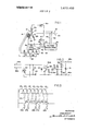
BRIEF DESCRIPTION OF THE DRAWINGS FIG. 1 is a schematic diagram of one form of alternator and regulator control system of this invention wherein a rotary transformer is associated with the alternator;
FIG. 2 is a voltage regulator which can be used in the circuit of FIG. 1;
FIG. 3 is a series of waveforms which represent the output of the alternator and regulator control system of FIG. 1;
FIG. 4 is an alternate form of alternator and regulator control system constructed in accordance with this invention; and
FIG. 5 illustrates the several power curves obtained both from full wave and half wave alternator outputs of conventional design and also shows the marked improvement of alternator output when using the high reverse voltage pulses in accordance with this invention.
DESCRIPTION OF THE ILLUSTRATES EMBODIMENTS Referring now to FIG. I there is seen an alternator and regulator control system designated generally by reference numeral 10. The alternator is illustrated as having an output winding 12, which is generally the stator of the alternator, and a rotating field winding 14. The field winding 14 is energized to provide a magnetic field which, in turn, induces an alternating current voltage in the output windings 12. In the illustrated embodiment, the output windings 12 are connected in WYE configuration with windings 12a, 12b and 12c connected together at a common circuit point 13 which, in turn, is here illustrated at the positive output terminal of the system.
Output diodes 16a, 16b and 16c are connected to the windings 12a, 12b and 120, respectively, to rectify the alternating current voltage induced in these windings to produce a direct current voltage across the output terminals 18 and 20. It will be noted that this is three phase half wave rectification where only three diodes are used rather than the usual six diode full wave configuration. When the cathode electrodes of diodes 16a, 16b and 160 are negative the alternating current voltage is delivered to terminals 18 and 20 in the form of pulsating DC. However, at the end of each negative half cycle, the diodes are instantly rendered nonconductive in the usual manner. This rapid nonconduction of the diodes causes a reverse voltage condition to exist in the stator windings 12a, 12b and in successive sequence in accordance with their sequence of energization. Heretofore, this reverse voltage pulse or kickback voltage was dissipated within the system and this energy was lost. In accordance with the general concepts of this invention, these reverse voltage pulses are fed back to the field winding 14 to energize the alternator system. 7
For a better understanding of the operation of the alternator and regulator control system of FIG. 1, reference is now made to FIG. 3 which illustrates the half wave pulses 22 which occur at the output of winding 12b, and the half wave pulses 24 which occur at the output winding-12c. I-Ialf wave pulses 26 which occur at the output winding 12a are also illustrated, but the reverse voltage pulses that are produced by these pulses are not used for field excitation. At the bottom of each pulse, a broken line indicates the high voltage short time duration reverse voltage kickback pulse 22a, 24a and 26a for the associated pulses 22, 24 and 26, respectively. Pulses 22b and 24b correspond to the reverse voltage pulses and are delivered to a rotary transformer 32 at each end thereof from windings 12b and 12c in time relation so that current passes alternately in one direction and then in the other direction through the primary winding 32a. Also, since the reverse pulses are obtained from across two windings 12b and 12c the net voltage is twice that otherwise obtained and the small amount of residual magnetism remaining in the system is then sufficient to initiate operation of the alternator.
The primary winding 32a is connected to a voltage regulator 40 to have the circuit thereof open and close in response to a switching mechanism indicated by 42 connected between the lines 44 and 46. When the switch 42 is open, no current passes through the primary winding 32a and no pulses are trans former coupled across the rotary transformer 32. However, upon sensing the output voltage at terminals 18 and 20, this being accomplished over lines 48 and 50, switch 42 closes and pulses of current then pass through the primary winding. Pulses of current which are transformer coupled into the rotary secondary winding 32b are rectified to produce a DC voltage by a plurality of diodes 33 which form the bridge rectifier circuit 34. The output of the bridge circuit 34 is filtered by a capacitor 36 and applied to the field winding 14 as a DC or a pulsating DC current. The rotary secondary winding 32b, the bridge circuit 34, and capacitor 36 and field winding 14 are all mounted on a common shaft for rotation therewith thus eliminating the need for brushes or other mechanical connections to the field winding.
The voltage regulator 40 may take any convenient form, which will sense variations in output voltage across terminals 18 and 20 and operatively energize and tie-energize the switching device 42. The switching device 42 may be any relatively fast acting electronically or electrically controlled switching device.
Referring now to FIG. 2, a voltage regulator switching circuit 40A illustrates one such form of voltage regulator which can be used in the circuit of FIG. 1. The regulator 40A has input lines 48a and 50a corresponding to lines 48 and 50 of FIG. 1 for receiving the energizing voltage. A reverse bias protection diode 51 is connected across these lines and a voltage divider network including resistors 52 and 53 together with a thermistor S4 and capacitor 56 form the basic temperature compensation network for the regulator circuit. Variations in ambient temperature are thus compensated by changes in resistance value of the thermistor S4. The center tap 55 of the voltage divider network is then applied to the base electrode of a transistor 57 through a zener diode 58 which provides a reference voltage for regulation. A control current is developed across a biasing resistor 59 between the base and emitter electrodes of transistor 56 while the collector emitter electrodes are shunted by a capacitor 60 which absorbs any spikes or increased voltage transients that occur in the circuit. The output of transistor 57 is connected to the gate electrode of a triac 62 through a diode 63. Although a trial is shown in this embodiment it will be understood that any device of the applied to the gate electrode thereof. A capacitor 64 is connected between the gate electrode of the triac and the line 44a to filter extraneous signals to prevent inadvertent conduction of the triac. When voltage at output terminals 18 and 20 is greater than the desired output voltage, the zener diode 58 will conduct which, in turn, renders transistor 57 conductive to reverse bias the gate electrode of the triac 62 and maintain it in an open circuit or nonconductive condition. However, when voltage across terminals 18 and 20 decreases below a predetermined voltage value, zener diode 58 becomes nonconductive and transistor 57 similarly becomes nonconductive. This allows the pulses applied to the triac to pass through the gate electrode thereof more freely and through capacitor 64 to render the triac conductive and perform its switching function and allow the reverse voltage pulses to be applied to the rotary transformer 32.
Referring now to FIG. 4 there is seen an alternate form of an alternator and regulator control system constructed in accordance with this invention, which is designated generallyv by reference numeral 70. The control system includes the output windings 72 of an alternator, shown here connected in WYE configuration with the center common terminal 73 thereof connected to ground potential. A field winding 74 of the alternator is located in close proximity to the output winding 72 to develop a magnetic field and induce alternating current voltage in the output windings. The output windings 72a, 72b and 720 are connected to output diodes 76a, 76b and 760, respectively, to deliver half wave pulses of direct current to the positive output terminal 77. The output terminals 77 and 78 are of opposite polarity than that shown in FIG. 1, it being understood that mere reversal of connection of the diodes or other semiconductor components will change the polarity of the output voltage. When diodes 76a, 76b and 76c are rendered nonconductive, they produce a high voltage reverse voltage pulse in their associated winding which is then delivered to the field winding 74 through a feedback circuit 80. Here the feedback circuit 80 consists merely of a silicon controlled rectifier 82 which has its anode connected to the output windings 72 and its cathode connected to the field winding 74. The gate electrode of silicon controlled rectifier 84 is controlled by a voltage regulator circuit designated generally by 83. A voltage developing resistor 84 is connected between the gate and cathode of silicon controlled rectifier 82 and a turn on resistor 86 is connected to the gate of silicon controlled rectifier 82 and to an ignition terminal 87. Therefore, upon turning on the ignition switch of an automobile, the regulator system is placed in readiness for operation when the engine turns the alternator rotor. To provide a slight magnetic field for initial operation, the field winding 74 is connected to the ignition terminal 87 through a resistor 88 which is of relatively high resistance value, but which allows sufficient current flow through the field winding to produce a slight magnetic field to initiate start up of the charging system. The alternator field 74 is shunted by a diode 89 which serves to prevent recirculating currents from developing high voltages with the field winding.
The alternator and regulator circuit system of FIG. 4 operates in substantially the same manner as that disclosed with regard to FIG. 1 in that current through the field winding is developed as a result of the reverse voltage pulses developed in the output windings by rapid nonconduction of the output diodes 76a, 76b and 760. These reverse voltage pulses may have a magnitude of about 4 times greater than that of the normal half wave pulses applied to the output terminal and thus provides a very efficient output voltage from the alternator system.
An indicating lamp 96 receives operating potential via a pair of diodes 91 and 92 connected to the output windings 72a and 72b, respectively. This applies two of the three output pulses to line 93 which, in turn, has the terminal 94 arranged for connection to the indicating lamp 96 which is located within the automobile. The indicating lamp 96 has the other end thereof connected to battery potential and, when the ignition switch is closed, no current passes through the diodes 91 and 92 and the lamp is energized from the battery voltage through a load resistor 97. However, when output voltage is obtained from the alternator, line 93 becomes positive to about the same voltage value as that of the battery and a no voltage condition exists across the indicating lamp 96 to extinguish it. Only the two diodes 91 and 92 are needed to de-energize the lamp 96 because of the increased voltage obtained from the stator windings 72a and 72b. Prior to the development of this invention three diodes were needed for this function.
The current control transistor 99 is connected to the gate electrode of silicon controlled rectifier 82 to control its operation. A transistor 100 is operated as a zener diode by having its collector electrode tied back to its base electrode and the base emitter junction connected in series with the base electrode of a transistor 101. Transistor 101 functions as a temperature compensating unit. Transistor 99 is then rendered operative to short circuit the gate cathode circuit of silicon controlled rectifier 82 to disable the rectifier. On the other hand, when bias voltage is removed from resistors 102 and 103, transistor 99 is rendered inoperative, which, in turn will cause conduction of silicon controlled rectifier 82 via its voltage dropping resistor 84. The voltage setting at the output terminals 77 and 78 can be adjusted by a variable voltage divider network comprising a resistor 106 and a potentiometer 107 which is connected to the transistor 100 which is connected to act as a zener diode. The potentiometer 107 is shunted by a filter capacitor 109 which eliminates extraneous signals from being applied through the zener diode.
Silicon controlled rectifier 82 operates with the same function as the triac 62 of FIG. 2, and the switch means 42 of FIG. 1. It allows the reverse voltage pulses to be applied to the field winding 74 only when in the conductive state and blocks such pulses when rendered nonconductive by the voltage regulator circuit 83.
For a better understanding of the improved power output obtained by this invention reference is now made to the graph shown in FIG. 5 which shows output amperes versus alternator rpm. Here the curve 120 shows the typical full wave output of a conventional alternator regulator arrangement. With the average usable range of alternator rpm between 3,000 and 8,000 rpm the output is substantially constant at about 40 amperes for this type of alternator. When a half wave output arrangement is used within low rpm range, it will produce a reduced power output, but at the higher rpm range the power output will be increased as shown by the curve 121. In both cases the field was fed an excitation voltage from the battery or charging system. When using the arrangement of the present invention on the very same alternator the output is so greatly increased that excessive amounts of current can be obtained, this being shown by the partial solid and partial broken line curve 122. To prevent damage to the alternator a ohm resistor was inserted into the field line to limit the voltage applied thereto. The output power obtained with the IQ ohm resistor is shown by the curve 123 which reaches 100 amperes for a machine that previously reached only 40 amperes on full wave and 65 amperes on halfwave.
What has been described is a simple and efficient alternator and regulator control system which utilizes the reverse voltage pulses generated in the output windings as a result of rapid nonconduction of the output diodes to produce a control cur rent for the field winding of the alternator.
I claim:
1. An alternator and regulator control system comprising in combination, output windings for developing an alternating current output voltage having first and second polarities, a field winding positioned adjacent said output windings for developing a magnetic field to induce the alternating current output voltage into said output windings, rectifier means connected to said output voltage to rectify said alternating current output voltage, said rectifier means being highly conductive with said output voltage of the first polarity to pass unidirectional current and being highly nonconductive with said output voltage of the second polarity to block current, and the transition from conduction to nonconduction of said rectifier means producing a reverse voltage pulse in said output windings, and feedback means connected between said output windings and said field winding to utilize said reverse voltage pulses for energizing of said field winding.
2. The alternator and regulator control system of claim I wherein said feedback means includes a rotary transformer for receiving said reverse voltage pulses, said rotary transformer including a fixed primary winding for said reverse voltage pulses and a rotating secondary winding rotatable with said field winding, and a second rectifier means connected between said rotating secondary winding and said field winding to deliver direct current pulses to said field winding to produce a magnetic field therein.
3. The alternator and regulator control system of claim 2 wherein said second rectifier means is a bridge rectifier circuit.
4. The alternator and regulator control system of claim 1 wherein said feedback means includes a silicon controlled rectifier having load electrodes and a control electrode, said load electrodes connected between said output winding and said field winding for passing said reverse voltage pulses to produce a magnetic field within said field winding, and regulator means for controlling the gate electrode of said silicon controlled rectifier to render the same conductive and nonconductive in response to demands for output voltage from the said output windings.
5. The alternator and regulator control system of claim 4 wherein said silicon controlled rectifier has its anode connected to said output windings and its cathode connected to said field winding.
6. An alternator and regulator control system comprising in combination, a first winding means for developing an alternating current voltage output, a second winding means positioned adjacent said first winding means for developing a magnetic field to induce the alternating current output voltage into said first winding means, means connected to said first winding means to convert the alternating current output voltage to a direct current voltage by passing current of one polarity and blocking current of the other polarity such that the transition from a current passing condition to a current blocking condition causing reverse voltage pulses to be developed in said first winding means, feedback means for delivering said reverse voltage pulses from said first winding means to said second winding means to develop the magnetic field therein, and regulator circuit means having terminals connected to said means for converting said alternating current output voltage to said direct current voltage to sense the value thereof and produce a control signal, said regulator circuit means including switch means responsive to said control signal to switchably connect said reverse voltage pulses from said first winding means to said second winding means.
7. The alternator and regulator control system of claim 6 wherein said switch means of said regulator circuit means is a silicon controlled rectifier having the anode thereof connected to said means for converting said alternating current output voltage to said direct current voltage and the cathode thereof connected to said second winding means.
8. The alternator and regulator control system of claim 6 wherein said switch means is a triac which allows pulses of current to pass in both directions, and further including a rotary transformer having the fixed primary winding thereof connected in series with said triac to receive said reverse voltage pulses and a rotary secondary winding thereof connected to said second winding means through a bridge rectifier circuit.
9. The alternator and regulator control system of claim 6 further including a light indicating circuit consisting of a lamp having one terminal connected to a battery supply of the control system, and two diodes connected to said first winding means and the other terminal of said lamp to provide a counteracting voltage thereto and extinguish the lamp.

Claims (9)

1. An alternator and regulator control system comprising in combination, output windings for developing an alternating current output voltage having first and second polarities, a field winding positioned adjacent said output windings for developing a magnetic field to induce the alternating current output voltage into said output windings, rectifier means connected to said output voltage to rectify said alternating current output voltage, said rectifier means being highly conductive with said output voltage of the first polarity to pass unidirectional current and being highly nonconductive with said output voltage of the second polarity to block current, and the transition from conduction to nonconduction of said rectifier means producing a reverse voltage pulse in said output windings, and feedback means connected between said output windings and said field winding to utilize said reverse voltage pulses for energizing of said field winding.
2. The alternator and regulator control system of claim 1 wherein said feedback means includes a rotary transformer for receiving said reverse voltage pulses, said rotary transformer including a fixed primary winding for said reverse voltage pulses and a rotating secondary winding rotatable with said field winding, and a second rectifier means connected between said rotating secondary winding and said field winding to deliver direct current pulses to said field winding to produce a magnetic field therein.
3. The alternator and regulator control system of claim 2 wherein said second rectifier means is a bridge rectifier circuit.
4. The alternator and regulator control system of claim 1 wherein said feedback means includes a silicon controlled rectifier having load electrodes and a control electrode, said load electrodes connected between said output winding and said field winding for passing said reverse voltage pulses to produce a magnetic field within said field winding, and regulator means for controlling the gate electrode of said silicon controlled rectifier to render the same conductive and nonconductive in response to demands for output voltage from the said output windings.
5. The alternator and regulator control system of claim 4 wherein said silicon controlled rectifier has its anode connected to said output windings and its cathode connected to said field winding.
6. An alternator and regulator control system comprising in combination, a first winding means for developing an alternating current voltage output, a second winding means positioned adjacent said first winding means for developing a magnetic field to induce the alternating current output voltage into said first winding means, means connected to said first winding means to convert the alternating current output voltage to a direct current voltage by passing current of one polarity and blocking current of the other polarity such that the transition from a current passing condition to a current blocking condition causing reverse voltage pulses to be developed in said first winding means, feedback means for delivering said reverse voltage pulses from said first winding means to said second winding means to develop the magnetic field therein, and regulator circuit means having terminals connected to said means for converting said alternating current output voltage to said direct current voltage to sense the value thereof and produce a control signal, said regulator circuit means including switch means responsive to said control signal to switchably connect said reverse voltage pulses from said first winding means to said second winding means.
7. The alternator and regulator control system of claim 6 wherein said switch means of said regulator circuit means is a silicon controlled rectifier having the anode thereof connected to said means for converting said alternating current output voltage to said direct current voltage and the cathode thereof connected to said second winding means.
8. The alternator and regulator control system of claim 6 wherein said switch means is a triac which allows pulses of current to pass in both directions, and further including a rotary transformer having the fixed primary winding thereof connected in series with said triac to receive said reverse voltage pulses and a rotary secondary winding thereof connected to said second winding means through a bridge rectifier circuit.
9. The alternator and regulator control system of claim 6 further including a light indicating circuit consisting of a lamp having one terminal connected to a battery supply of the control system, and two diodes connected to said first winding means and the other terminal of said lamp to provide a counteracting voltage thereto and extinguish the lamp.
US169431A 1971-08-05 1971-08-05 Alternator and regulator control system Expired - Lifetime US3673489A (en)

Applications Claiming Priority (1)

Application Number Priority Date Filing Date Title
US16943171A 1971-08-05 1971-08-05

Publications (1)

Publication Number Publication Date
US3673489A true US3673489A (en) 1972-06-27

Family

ID=22615657

Family Applications (1)

Application Number Title Priority Date Filing Date
US169431A Expired - Lifetime US3673489A (en) 1971-08-05 1971-08-05 Alternator and regulator control system

Country Status (8)

Country Link
US (1) US3673489A (en)
JP (1) JPS4825811A (en)
DE (1) DE2238500A1 (en)
FR (1) FR2149924A5 (en)
GB (1) GB1346284A (en)
IT (1) IT961776B (en)
NL (1) NL7210740A (en)
SE (1) SE372150B (en)

Cited By (10)

* Cited by examiner, † Cited by third party
Publication number Priority date Publication date Assignee Title
WO1981003403A1 (en) * 1980-05-22 1981-11-26 Motorola Inc Field coil fault detector for automotive alternator battery charging systems
US4470003A (en) * 1983-04-11 1984-09-04 Ford Motor Company Voltage regulator with temperature responsive circuitry for reducing alternator output current
FR2543758A1 (en) * 1983-03-31 1984-10-05 Sundstrand Corp ELECTRICITY GENERATING SYSTEM WITH EXCITATION IN DEFAULT CONDITIONS
US5233285A (en) * 1990-11-27 1993-08-03 Valeo Equipemento Electriques Moteur Voltage regulator device for charging a battery by an alternator
US5376876A (en) * 1992-06-25 1994-12-27 Motorola, Inc. Phase winding detector and alternator charging system
US6215271B1 (en) 1999-05-11 2001-04-10 Satcon Technology Corporation Charging system having a controlled rectifier bridge and a single voltage sensor
US6239582B1 (en) 1999-11-04 2001-05-29 Satcon Technology Corporation Motor vehicle alternator having a single voltage sensor and a half-wave controlled rectifier bridge for increasing output
US20020149347A1 (en) * 2001-04-16 2002-10-17 Denso Corporation Battery charging system and vehicle generator control system
US20130293194A1 (en) * 2012-05-02 2013-11-07 Remy Technologies, Llc Alternator with lockout mode
US20140266080A1 (en) * 2011-11-28 2014-09-18 Abb Technology Ag Rotating electrical machine

Citations (3)

* Cited by examiner, † Cited by third party
Publication number Priority date Publication date Assignee Title
US3260917A (en) * 1960-08-09 1966-07-12 Simms Motor Units Ltd Electrical supply systems with means responsive to the output of said system
US3299342A (en) * 1965-11-12 1967-01-17 Gen Motors Corp Semiconductor voltage regulator
US3544881A (en) * 1968-09-11 1970-12-01 Gen Motors Corp Transistor voltage and current regulating system for an alternating current generator

Patent Citations (3)

* Cited by examiner, † Cited by third party
Publication number Priority date Publication date Assignee Title
US3260917A (en) * 1960-08-09 1966-07-12 Simms Motor Units Ltd Electrical supply systems with means responsive to the output of said system
US3299342A (en) * 1965-11-12 1967-01-17 Gen Motors Corp Semiconductor voltage regulator
US3544881A (en) * 1968-09-11 1970-12-01 Gen Motors Corp Transistor voltage and current regulating system for an alternating current generator

Cited By (14)

* Cited by examiner, † Cited by third party
Publication number Priority date Publication date Assignee Title
WO1981003403A1 (en) * 1980-05-22 1981-11-26 Motorola Inc Field coil fault detector for automotive alternator battery charging systems
US4314193A (en) * 1980-05-22 1982-02-02 Motorola, Inc. Field coil fault detector for automotive alternator battery charging systems
FR2543758A1 (en) * 1983-03-31 1984-10-05 Sundstrand Corp ELECTRICITY GENERATING SYSTEM WITH EXCITATION IN DEFAULT CONDITIONS
US4470003A (en) * 1983-04-11 1984-09-04 Ford Motor Company Voltage regulator with temperature responsive circuitry for reducing alternator output current
US5233285A (en) * 1990-11-27 1993-08-03 Valeo Equipemento Electriques Moteur Voltage regulator device for charging a battery by an alternator
US5376876A (en) * 1992-06-25 1994-12-27 Motorola, Inc. Phase winding detector and alternator charging system
US6215271B1 (en) 1999-05-11 2001-04-10 Satcon Technology Corporation Charging system having a controlled rectifier bridge and a single voltage sensor
US6239582B1 (en) 1999-11-04 2001-05-29 Satcon Technology Corporation Motor vehicle alternator having a single voltage sensor and a half-wave controlled rectifier bridge for increasing output
US20020149347A1 (en) * 2001-04-16 2002-10-17 Denso Corporation Battery charging system and vehicle generator control system
US6700353B2 (en) * 2001-04-16 2004-03-02 Denso Corporation Battery charging system and vehicle generator control system
US20140266080A1 (en) * 2011-11-28 2014-09-18 Abb Technology Ag Rotating electrical machine
US9325225B2 (en) * 2011-11-28 2016-04-26 Abb Technology Ag Rotating electrical machine
US20130293194A1 (en) * 2012-05-02 2013-11-07 Remy Technologies, Llc Alternator with lockout mode
US9199588B2 (en) * 2012-05-02 2015-12-01 Remy Technologies, Llc Alternator with lockout mode

Also Published As

Publication number Publication date
IT961776B (en) 1973-12-10
SE372150B (en) 1974-12-09
NL7210740A (en) 1973-02-07
DE2238500A1 (en) 1973-02-22
JPS4825811A (en) 1973-04-04
GB1346284A (en) 1974-02-06
FR2149924A5 (en) 1973-03-30

Similar Documents

Publication Publication Date Title
US3300704A (en) Regulated electrical supply system
US3009091A (en) Electric generating systems
US3710226A (en) Generator with multiple voltage regulators
US7705568B2 (en) Power-generator control apparatus for addressing occurrence of voltage transient
US3673489A (en) Alternator and regulator control system
US3343059A (en) Semiconductor generator voltage regulator system
US4281279A (en) Chopper-controlled alternator for battery charging
US3456182A (en) Potential regulator circuit
US3821619A (en) Speed control system for reversible electrical machine
US3321688A (en) A.c./d.c. fed transistorized induction motors
US4181875A (en) Drive circuit for a DC motor
US3263155A (en) Voltage regulator for generators
US3137811A (en) Semiconductor voltage regulator
US3173074A (en) Voltage regulator with rc-control
US3293536A (en) Electronic voltage regulator with output transistor biased by isolation diode
US3369170A (en) Potential regulator circuit for permanent magnet type alternators
US3609514A (en) Generator voltage regulator
GB954411A (en) Field circuit control for a.c. generators
US3626273A (en) Voltage regulator arrangement for preventing overvoltages
US3702433A (en) Alternator regulator circuit
US3136940A (en) Transistor voltage regulator for a generator with means for preventing discharge of battery through field winding or output winding
US3771045A (en) D-c power supply system fed from an a-c generator
KR100216015B1 (en) Output voltage control device of AC generator
US3427529A (en) Potential regulator circuit
US3332004A (en) Electrical generator system

Legal Events

Date Code Title Description
AS Assignment

Owner name: PRESTOLITE ELECTRIC INCORPORATED, FOUR SEAGATE, TO

Free format text: ASSIGNMENT OF ASSIGNORS INTEREST.;ASSIGNOR:MOTOROLA, INC.;REEL/FRAME:004997/0236

Effective date: 19871116

AS Assignment

Owner name: PEI 1991 ACQUISITION, INC., OHIO

Free format text: ASSIGNMENT OF ASSIGNORS INTEREST;ASSIGNOR:PRESTOLITE ELECTRIC INCORPORATED;REEL/FRAME:005967/0628

Effective date: 19911029

Owner name: PEI 1991 ACQUISITION, INC.

Free format text: ASSIGNMENT OF ASSIGNORS INTEREST.;ASSIGNOR:PRESTOLITE ELECTRIC INCORPORATED;REEL/FRAME:005967/0628

Effective date: 19911029