US36733A - Improvement in grain-screens - Google Patents
Improvement in grain-screens Download PDFInfo
- Publication number
- US36733A US36733A US36733DA US36733A US 36733 A US36733 A US 36733A US 36733D A US36733D A US 36733DA US 36733 A US36733 A US 36733A
- Authority
- US
- United States
- Prior art keywords
- screen
- grain
- screens
- improvement
- framing
- Prior art date
- Legal status (The legal status is an assumption and is not a legal conclusion. Google has not performed a legal analysis and makes no representation as to the accuracy of the status listed.)
- Expired - Lifetime
Links
Images
Classifications
-
- B—PERFORMING OPERATIONS; TRANSPORTING
- B07—SEPARATING SOLIDS FROM SOLIDS; SORTING
- B07B—SEPARATING SOLIDS FROM SOLIDS BY SIEVING, SCREENING, SIFTING OR BY USING GAS CURRENTS; SEPARATING BY OTHER DRY METHODS APPLICABLE TO BULK MATERIAL, e.g. LOOSE ARTICLES FIT TO BE HANDLED LIKE BULK MATERIAL
- B07B1/00—Sieving, screening, sifting, or sorting solid materials using networks, gratings, grids, or the like
- B07B1/28—Moving screens not otherwise provided for, e.g. swinging, reciprocating, rocking, tilting or wobbling screens
- B07B1/38—Moving screens not otherwise provided for, e.g. swinging, reciprocating, rocking, tilting or wobbling screens oscillating in a circular arc in their own plane; Plansifters
Definitions
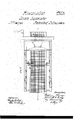
- Figure l is a side sectional view of our invention, taken in the line wir, Fig. 2; Fig. 2, a'plan or top View of the same.
- This invention consists in placing 'the screen on a fixed 4or adjustable bar between friction- ⁇ rollers or. other bearing-surlaees'and operat- -Ing the screen through the medium of acrank or crank-wheel, all arranged in such a manner that a combined longitudinal and lateral vibratory ⁇ 1novement is giventhe ⁇ screen,y
- A represents a framing, which may be con# strncted in any proper manner, and having at one end of it a drivingfshaft, B, which is placed transversely iu the framing and p1ovided at one end with a pulley, C.
- L is an inclined screen, which may be constructed inthe ordinary wayto'wit, a wirecloth,a, attached to a rectangular frame, M,
- This comv bined .longitudinal and lateralmovemcntlof the screen renders it very efficient in separat# ing chess, cockle, and other impurities from, the grain.-
- the screen is' not liable to choke orgiillup, nor is the -grain'jallowed to pass through the screen with the cockle and chess, but is made to pass freely valong on the'scre'en and be vdischarged atit's lower or depressed end.
- This movement of the rscreenrend'ers the use of all knocking devices unnecessary, as vwell 'as sudden jarrings, which have va tendency to ll up the meshes of the screen,
- the adjustable bar P provided wvith the friction-rollers d d, or equivalent side bearirig- witnesseses: surfaces for ⁇ the screen L, in combination with A. ANDERSON, a crank or crank-wheel, J on which the upl LEVI BUSH.
Landscapes
- Combined Means For Separation Of Solids (AREA)
Description
UNITED STATES PATENT f OFFICE. i
IMPROVEMENT I'N GRAIN-SCREENS..
Specification forming part of Letters Patent No. 36.732, dated October 31, 1862.
Toull whom it may concern..-
Beit known that we, WILLIAM Rowan and .TAIIIEs M. H.GILL, of Freeport, in the county of vArmstrong and uState .of ,'Pennsylvania, have invented a new and ImprovedGrain- Screen for the Purpose of Separating Chess, Cookie, and other Impurities from Grain; andV we do hereby declare .that the following is a full., clear, and exact description of the same, reference Ibeing had to the accompanying drawings, making a part of this specification,
Figure l is a side sectional view of our invention, taken in the line wir, Fig. 2; Fig. 2, a'plan or top View of the same.
, Similar letters of reference indicate correspending parts in the two iigures.
This invention consists in placing 'the screen on a fixed 4or adjustable bar between friction-` rollers or. other bearing-surlaees'and operat- -Ing the screen through the medium of acrank or crank-wheel, all arranged in such a manner that a combined longitudinal and lateral vibratory`1novement is giventhe` screen,y
.. 'whereby the' same is rendered niuch more4 efficient in its operation than those previously devised, and also admittingof the screen be#4 ing readilyI detached from its framing when necessary for the purpose of cleansing, re-
pairing, &c.
To enable-those skilled in the art` to fully understand and construct our invention, `we
will proceed Vto describe it. l
A represents a framing, which may be con# strncted in any proper manner, and having at one end of it a drivingfshaft, B, which is placed transversely iu the framing and p1ovided at one end with a pulley, C.
Dis a shaftwhich is placed'iny the lower part of the framing A, parallel with shaft B,
and having a pulley, E, on its outer end, around which and the pulley C a baud or belt, F, passes. At the inner end of theV shaft D there is a bevel-wheel, G, which gears into a vcorresponding wheel, H, at thelowe'r part of a Vertical shaft, I, said shaft having a wheel,
J, on its upper end, which is provided wilha vertical pin, K, near its periphery.
L is an inclined screen, which may be constructed inthe ordinary wayto'wit, a wirecloth,a, attached to a rectangular frame, M,
.a short and ccarsefinclined screen, N, being placed overthe feed end` of screen L,` directly underneath the hopper O, on the framing A. These-reen N is inclined in a reverse'direction to the screen L,as shown clearly in Fig. l. The screen L extends the whole length of theframing A, and it rests on a bar, P, which is fitted in notches b in the side bars, c c, of the framing. n this bar P there are placed two.
-friction-rllers, dd, one near eaehend. .These rollers `haven. horizontal position onthebar P, ,and they bear against the sidese e of the fraie- M,*while the Vframe M'of the screen -restsnpon vertical friction-rollers a', asshown in Fig.11. The upper or highcrend of l the screen L rests on the pin K, lthe latter fitting.
inl a hole in a. crosspiece, f, at the bottdmof l'said screen. Y, IFrom the -abovede'scription it will'beseen that when the shaft I' is rotated 'throughfthe' medium of the belt and .gearing-'previously described, a combined longitudinal and'flat- 'eral vibratory movement will be givenjthe .screen L,.theroll/ers d d `serving as bearings' i for the screen, so as to give ita lateralr'o'clc` .ing jmovement, and this movement maybe modied so as to be increased or diminished at thefeed-or discharge end of the screen L by shifting the position of thel bar P, the lateV ter-being 'fitted in any of a series of notches, b, 1 whichare made in the bars -c c. This comv bined .longitudinal and lateralmovemcntlof the screen renders it very efficient in separat# ing chess, cockle, and other impurities from, the grain.- The screen is' not liable to choke orgiillup, nor is the -grain'jallowed to pass through the screen with the cockle and chess, but is made to pass freely valong on the'scre'en and be vdischarged atit's lower or depressed end. This movement of the rscreenrend'ers the use of all knocking devices unnecessary, as vwell 'as sudden jarrings, which have va tendency to ll up the meshes of the screen,
andralso cause a 0rent deal cf wear and tear, especially if thescreen be rapidlydriven.- Thefraniing isprovidedwitha top or cover,
Q,which may be readily removed, Whennecessary, fas `wellfas the screen,;the latter be-,
ing merely required to be lifted from the bar P.
we claim as new, and desire to secure by Leb- Having thusdescribed our invention,- whab per or feed end of the screen rests, substan- I tiully as and for the purpose set forth l WM. ROWAN.
ters Patent, is
JAS. M. H. GILL.
The adjustable bar P, provided wvith the friction-rollers d d, or equivalent side bearirig- Witnesses: surfaces for `the screen L, in combination with A. ANDERSON, a crank or crank-wheel, J on which the upl LEVI BUSH.
Publications (1)
| Publication Number | Publication Date |
|---|---|
| US36733A true US36733A (en) | 1862-10-21 |
Family
ID=2106310
Family Applications (1)
| Application Number | Title | Priority Date | Filing Date |
|---|---|---|---|
| US36733D Expired - Lifetime US36733A (en) | Improvement in grain-screens |
Country Status (1)
| Country | Link |
|---|---|
| US (1) | US36733A (en) |
-
0
- US US36733D patent/US36733A/en not_active Expired - Lifetime
Similar Documents
| Publication | Publication Date | Title |
|---|---|---|
| US36733A (en) | Improvement in grain-screens | |
| US29483A (en) | Device eob bolting floub | |
| US782618A (en) | Crackling-press. | |
| US25536A (en) | strause | |
| US348019A (en) | Cider-press | |
| US508958A (en) | Cider-mill | |
| US121197A (en) | Improvement in flour-sifters | |
| US935630A (en) | Eccentric ore-crusher. | |
| US719337A (en) | Combined flour tank and sifter. | |
| US111913A (en) | Improvement in vegetable-crushers | |
| US40238A (en) | Improvement in smut-mills | |
| US29998A (en) | Fawning-mill | |
| US167013A (en) | Improvement in fruit and jelly presses | |
| US174828A (en) | Improvement in grain-screens | |
| US450606A (en) | Attachment for hominy-mills | |
| US20899A (en) | Machine | |
| US143127A (en) | Improvement in panning-mills | |
| US110291A (en) | Improvement in fanning-mllls | |
| US214560A (en) | Improvement in wine or cider mills | |
| US40987A (en) | Improvement in mills for grinding fruit, grain | |
| US175804A (en) | Improvement in curd-drainers | |
| US72872A (en) | William lucas | |
| US78624A (en) | Improvement in geinddtg-mills | |
| US35953A (en) | Improvement in flour-bolts | |
| US27709A (en) | Millstone-bush |