US366384A - Iechanism for transferring coils of wire - Google Patents
Iechanism for transferring coils of wire Download PDFInfo
- Publication number
- US366384A US366384A US366384DA US366384A US 366384 A US366384 A US 366384A US 366384D A US366384D A US 366384DA US 366384 A US366384 A US 366384A
- Authority
- US
- United States
- Prior art keywords
- track
- platform
- transferring
- coils
- way
- Prior art date
- Legal status (The legal status is an assumption and is not a legal conclusion. Google has not performed a legal analysis and makes no representation as to the accuracy of the status listed.)
- Expired - Lifetime
Links
Images

Classifications
-
- B—PERFORMING OPERATIONS; TRANSPORTING
- B21—MECHANICAL METAL-WORKING WITHOUT ESSENTIALLY REMOVING MATERIAL; PUNCHING METAL
- B21C—MANUFACTURE OF METAL SHEETS, WIRE, RODS, TUBES, PROFILES OR LIKE SEMI-MANUFACTURED PRODUCTS OTHERWISE THAN BY ROLLING; AUXILIARY OPERATIONS USED IN CONNECTION WITH METAL-WORKING WITHOUT ESSENTIALLY REMOVING MATERIAL
- B21C47/00—Winding-up, coiling or winding-off metal wire, metal band or other flexible metal material characterised by features relevant to metal processing only
- B21C47/02—Winding-up or coiling
- B21C47/10—Winding-up or coiling by means of a moving guide
- B21C47/14—Winding-up or coiling by means of a moving guide by means of a rotating guide, e.g. laying the material around a stationary reel or drum
-
- Y—GENERAL TAGGING OF NEW TECHNOLOGICAL DEVELOPMENTS; GENERAL TAGGING OF CROSS-SECTIONAL TECHNOLOGIES SPANNING OVER SEVERAL SECTIONS OF THE IPC; TECHNICAL SUBJECTS COVERED BY FORMER USPC CROSS-REFERENCE ART COLLECTIONS [XRACs] AND DIGESTS
- Y10—TECHNICAL SUBJECTS COVERED BY FORMER USPC
- Y10S—TECHNICAL SUBJECTS COVERED BY FORMER USPC CROSS-REFERENCE ART COLLECTIONS [XRACs] AND DIGESTS
- Y10S242/00—Winding, tensioning, or guiding
- Y10S242/915—Coil gripper
Definitions
- the customary method of handling and transferring coiled wire rods as they come from the rolling-mill and are reeled up in hot condition is to seize them with suspended tongs and swing them to and deposit them upon a platform, truck, or car, upon which they are piled one upon another until the accumulated load is of the desired quantity to be removed to any designated part of the works.
- the attendant When loading up the platform or car, as the height of the piles of coils increases, the attendant is required to make greater exertion and effort to throw the hot coils with his tongs to the top of the pile, and especially is this transfer and handling laborious when the platform or car upon which the product or coils are deposited is at some considerable distance from the rolling-mill, reel, or place at which the product is taken.
- the objects of my present invention are, first, to provide means in an apparatus for transferring coiled wire rods or product from the mill or coiling apparatus to a receivingcar, platform, or place where the product of the mill is deposited as it is finished, whereby the rise due to the accumulation of the pro duct as it is piled upon the platform may be mechanically counteracted or overcome by variation in the distance from the platform surface to the point of suspension of the handling device or transferring carrier, so that the attendant handling the product can do so to best advantage, and will not be put to extraordinary exertions and labor required for throwing up the coils or raising the weight of the material beyond the normal swing of his tongs or handling-tool as the piles or load of material accumulates and is built higher and Serial No. 221,079. (No model.)
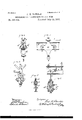
- Figure 1 is a vertical sectional view or elevation illustrating my invention as adapted in a plant or mechanism for transferring coiled wire rods as they come from a rolling-mill and are reeled to a receiving car or platform.
- Fig. 2 is a transverse section of the overhead track or transfer-way, showing an end view of the suspending traveler.
- Fig. 3 is a side view of the suspending traveler.
- Fig. 4 is a transverse sectional view showing the manner in which the track or way beam is connected by trunnions to its support ing hanger.
- Fig. 5 is a transverse section through the beam and traveler-shifting cylinder.
- Fig. 6 is a detail View illustrating the manner of operating the valve of the shifting cylinder.
- Ade notes the rollingmill for forming wire rods.
- B denotes the coiling apparatus, whereby said rods are reeled into coils as they come from the rolling-mill.
- said coiling mechanism is illustrated as pro- Vided witha platform and hydraulic lifting device, I), for raising the coil to a convenient positionfordischargingit.
- Myinvention may, however, be employed with any kind of reels or coiling apparatus and rod-forming machinery.
- the handling device or carrier D denotes the handling-tool or transferringcarrier by which the coils are removed from the reel B or place of delivery and transferred to the car, platform, or place of deposit E.
- the handling device or carrier D preferably consists of tongs: suspended and balanced in such manner that the attendant can readily operate them in lifting and swinging the coil from the reel to the car; but it will be understood that a hook, forked lever, or other equivalent may, if preferred, be used in'lieu of tongs such as shown.
- a hanger to which the beam is hung by trunnions tor other suitable connection,in a manner to allow the ends of said beam to swing up and down.
- J indicates hydraulic lifting mechanism sup-- ported on" the overhead frame of the building, and connected, as at J, with the'swinging track F, for elevating and depressing the same, accordingly as hydraulic pressure is let into and released from the cylinder through the pipe], under control of the valve K, which is provided with an operating-handle, K, at a convenient position for the operator.
- the traveler G is preferably made as indicated in Figs. 2 and 3, being provided with wheels G, that run upon the beam For on the flanges thereof, as indicated.
- L indicates a hydraulic cylinder supported upon the beam or track F, and provided with a suitable piston,the rodlof which connects with the traveler G for shifting said traveler back and forth along the transfer-way by the movement of the piston, when the water under pressure passes into and from said cylinder through the pipes m and m, accordingly as the valve M is shifted, under control of the attendant.
- N denotes a section of floor on which the attendant travels while he transfers the coils of wire rod. Said floor is hinged near the reeling mechanism B, as at a, while its opposite end is supported by the hydraulic lifting mechanism 0, the action of which is controlled by the valve 0, actuated by the handle O ,so
- the rod M of the valve M is connected to the rock-shaft R by a crank or arm, S, so that the rocking of said shaft B in one direction or the other effects the operation of shifting the valve M, and thereby controls the action of the hydraulic mechanism L for-advancing and retracting the traveler along the way or track F, for swinging the tongs or carrier and the coils or product supported thereby from the place of receiving to the place of deposit and back again.
- W indicates the water-supply pipe, and W the discharge-pipe, for the hydraulic mechanisms.
- a handling and transferring carrier of asuspended overhead supporting track or way and means, substantially as described, for varying the distance between said track and the top of the receiving car or platform whereon the product is to be deposited, for the purpose set forth.
- An apparatus for discharging coiled-wire rods comprising a suspended overhead track or way, a handling and transferring carrier" suspended from a traveler mounted on said track, a receiving car or platform, and a hy- 0 draulie lift-ing mechanism adapted for varying the distance between the receiving-platform and the track on which the carrieris suspended.
- An apparatus for discharging coiled-wire rods consisting of a suspended overhead track or way a handling and transferring carrier suspended from a traveler mounted on said track, a receiving ear or platform, a hydraulic lifting mechanism adapted for varying the distance between the receiving-platform and the track on which the carrier is suspended, and a shifting mechanism for automatically moving said traveler back and forth upon said track.
- V In an apparatus for discharging and transferring wire rods, the combination, with coil-producing mechanism and a receiving platform or car onto which to deposit the product, of an overhead track, a transferring-carrier supported and movable on said track, a
Landscapes
- Engineering & Computer Science (AREA)
- Mechanical Engineering (AREA)
- Winding, Rewinding, Material Storage Devices (AREA)
- Carriers, Traveling Bodies, And Overhead Traveling Cranes (AREA)
Description
(No Model.) 2 Sheets-Sheet 1.
F. H. DANIELS.
MECHANISM FOR TRANSPERRING OOILS 0F WIRE. No. 366,384. Patented July 12,1887.-
N O a .1 'IIL 27L N. PETERS. PnnwLnhn nim. wasm n nnnnnn C.
2 SheetsT-Sheet 2.
(No Model.)
F. H. DANIELS.
MECHANISM FOR TRANSFERRING GOILS 0F WIRE.
No. 366,384. Patentd July 12,1887.
' NITED' STATES PATENT OFFICE.
FRED H. DANIELS, OF VVOROESTER, MASSACHUSETTS.
MECHANISM FOR TRANSFERRING COILS OF WIRE.
SPECIFICATION forming part of Letters Patent No. 366,384., dated July 12, 1887.
Application filed Deeemherfi, 1886.
To aZZ whom, it may concern:
Be it known that I, FRED H. Dimmers, a citizen of the United States, residing at WVorcester, in the county of Worcester and State of Massachusetts, have invented certain new and useful Improvements in Mechanism for Transferring W'iredtod Coils, of which the following, together with the accompanying drawings,'is a specification sufficiently full, clear, and exact to enable persons skilled in the art to which this invention appertains to make and use the same.
The customary method of handling and transferring coiled wire rods as they come from the rolling-mill and are reeled up in hot condition is to seize them with suspended tongs and swing them to and deposit them upon a platform, truck, or car, upon which they are piled one upon another until the accumulated load is of the desired quantity to be removed to any designated part of the works. When loading up the platform or car, as the height of the piles of coils increases, the attendant is required to make greater exertion and effort to throw the hot coils with his tongs to the top of the pile, and especially is this transfer and handling laborious when the platform or car upon which the product or coils are deposited is at some considerable distance from the rolling-mill, reel, or place at which the product is taken.
The objects of my present invention are, first, to provide means in an apparatus for transferring coiled wire rods or product from the mill or coiling apparatus to a receivingcar, platform, or place where the product of the mill is deposited as it is finished, whereby the rise due to the accumulation of the pro duct as it is piled upon the platform may be mechanically counteracted or overcome by variation in the distance from the platform surface to the point of suspension of the handling device or transferring carrier, so that the attendant handling the product can do so to best advantage, and will not be put to extraordinary exertions and labor required for throwing up the coils or raising the weight of the material beyond the normal swing of his tongs or handling-tool as the piles or load of material accumulates and is built higher and Serial No. 221,079. (No model.)
higher above the surface of the platform or car upon which the product is deposited; second, to provide an elevating mechanism, in combination with an overhead track or way, whereby said way can be raised or depressed as desired; third, to provide means for elevating or depressing the floor upon which the attendant works in its relation to the car, platform, or place of deposit of the product; fourth, to provide convenient and practical means under control of the attendant for me chanically forcing the suspended handling device or carrier along the overhead track or way; fifth, to provide, in combination with suspended tongs or device for handling and transferring hot wire coils, of a swinging over head track or way with mechanism for advancing and retracting the suspended carrier along said way, and means for swinging the track to different inclinations for changing the relative height of the tongs or handling devices in relation to the platiormsurface upon which the product is deposited. These objects I attain by mechanism the nature and operation of which are shown in the drawings and explained in the following description, the particular subject-matter claimed being hereinafter deft nitel y specified.
In the drawings, Figure 1 is a vertical sectional view or elevation illustrating my invention as adapted in a plant or mechanism for transferring coiled wire rods as they come from a rolling-mill and are reeled to a receiving car or platform. Fig. 2 is a transverse section of the overhead track or transfer-way, showing an end view of the suspending traveler. Fig. 3 is a side view of the suspending traveler. Fig. 4 is a transverse sectional view showing the manner in which the track or way beam is connected by trunnions to its support ing hanger. Fig. 5 is a transverse section through the beam and traveler-shifting cylinder. Fig. 6 is a detail View illustrating the manner of operating the valve of the shifting cylinder.
In reference to parts, Adenotes the rollingmill for forming wire rods.
B denotes the coiling apparatus, whereby said rods are reeled into coils as they come from the rolling-mill.
In the present instance ICO said coiling mechanism is illustrated as pro- Vided witha platform and hydraulic lifting device, I), for raising the coil to a convenient positionfordischargingit. Myinvention may, however, be employed with any kind of reels or coiling apparatus and rod-forming machinery. i
B indicates a cover or guard for the reel, which cover is suspended from the piston of a hydraulic cylinder, 13, whereby it is raised for allowing access to the coil by hydraulic pressure in the cylinder, controlled by the valve b G indicates the coils of wire rod as reeled up for transfer.
D denotes the handling-tool or transferringcarrier by which the coils are removed from the reel B or place of delivery and transferred to the car, platform, or place of deposit E. The handling device or carrier D preferably consists of tongs: suspended and balanced in such manner that the attendant can readily operate them in lifting and swinging the coil from the reel to the car; but it will be understood that a hook, forked lever, or other equivalent may, if preferred, be used in'lieu of tongs such as shown.
or overhead frame H of the building by a hanger, I, to which the beam is hung by trunnions tor other suitable connection,in a manner to allow the ends of said beam to swing up and down.
J indicates hydraulic lifting mechanism sup-- ported on" the overhead frame of the building, and connected, as at J, with the'swinging track F, for elevating and depressing the same, accordingly as hydraulic pressure is let into and released from the cylinder through the pipe], under control of the valve K, which is provided with an operating-handle, K, at a convenient position for the operator.
The traveler G is preferably made as indicated in Figs. 2 and 3, being provided with wheels G, that run upon the beam For on the flanges thereof, as indicated.
L indicates a hydraulic cylinder supported upon the beam or track F, and provided with a suitable piston,the rodlof which connects with the traveler G for shifting said traveler back and forth along the transfer-way by the movement of the piston, when the water under pressure passes into and from said cylinder through the pipes m and m, accordingly as the valve M is shifted, under control of the attendant. V
N denotes a section of floor on which the attendant travels while he transfers the coils of wire rod. Said floor is hinged near the reeling mechanism B, as at a, while its opposite end is supported by the hydraulic lifting mechanism 0, the action of which is controlled by the valve 0, actuated by the handle O ,so
that said floor can be raised and depressed as desired. Along the under side of the floor is a rock-shaft, R, mounted in suitable bearings and provided with arms 0* and r, to which are connected pedal-bars P and P, that extend up through the floor N, so that the attendant can, by depressing the pedal-bar with his foot, rock the shaft one way or the other.
The rod M of the valve M is connected to the rock-shaft R by a crank or arm, S, so that the rocking of said shaft B in one direction or the other effects the operation of shifting the valve M, and thereby controls the action of the hydraulic mechanism L for-advancing and retracting the traveler along the way or track F, for swinging the tongs or carrier and the coils or product supported thereby from the place of receiving to the place of deposit and back again. a
W indicates the water-supply pipe, and W the discharge-pipe, for the hydraulic mechanisms.
In the operation of my improved apparatus, when the rod is completed and coiled, the attendant in charge of the reel raises the guardcover B and the reel-platform, which latter elevates the coil 0 to a position where it is seized by the attendant who handles the tongs or transferring-tool D. When he has the tongs gripped upon the coil, he places his foot 011 the pedal 1?, which rocks the shaft R and shifts the valve for admitting pressure through the pipe m to the rear end of cylinder L, forforcing forward the piston and rod Z, which is connected to the suspending traveler G, there'- by moving said traveler toward the outer end of the track or way F and transferring the carrier or suspending tongs and coil held therein from the reeling mechanism B to the car E or place of deposit, the attendant by his hold 011 the tongs Y guiding and depositing the coil as he may desire. When the coil has been placed upon the car, he places his foot upon the pedal P and by depressing it rocks the shaft It in opposite direction and shifts the position of the valve M, so that the pressure is let into the front end of cylinder L,
through pipe 'm, thereby forcing back the piston and retracting-the carrier G along the way F to return the carrier-tongs or handling-tool back to the reel for taking another coil.
As the piles of coils accumulate upon the car or platform and becomeof such a height that it is inconvenient for the attendant .to swing the coil to the top of the pile, pressure can be let onto the lifting mechanism J and the track or way F raised, thereby increasing the distance from the surface of the platform to said track, and consequently carrying the transfer-tongs in a higher plane in relation to the surface of the platform upon which the coils are deposited. In similar manner pressure may be let onto the lifting mechanism 0 and the floor N be raised, so as to increase its height above the level of the car or platform, thereby carrying the attendant to a height that will compensate for the increased height in the pile of coils upon the car. By thus raising the support from which the tongs are suspended and the floor upon which the attendant stands while effecting the transfer of the coils, the labor is rendered substantially uniform, whether the pile of coils upon the car or platform is high or low, and the necessity of extraordinary exertion on the part of the attendant for piling the coils to an inconvenient height or beyond the normal swing of the tongs is obviated.
What I claim as of my invention, and desire to secure by Letters Patent, is-
1. In a transferring apparatus, the combination, with a handling and transferring carrier, of asuspended overhead supporting track or way and means, substantially as described, for varying the distance between said track and the top of the receiving car or platform whereon the product is to be deposited, for the purpose set forth.
2. An apparatus for discharging coiled-wire rods, comprising a suspended overhead track or way, a handling and transferring carrier" suspended from a traveler mounted on said track, a receiving car or platform, and a hy- 0 draulie lift-ing mechanism adapted for varying the distance between the receiving-platform and the track on which the carrieris suspended.
, 3. The combination, with an overhead track or way, a suspended ha dling and transferring mechanism, and a receiving truck or platform, of an upwardly and downwardly adjustable floor, substantially as and for the purpose set forth.
4. The combination, with the transfer tongs or carrier and their suspending mechanism, of a hinged track or way and an elevating mechanism for raising and depressing the end of said track for varying the height of the carrier relatively to the platform whereon the product is deposited.
5. The combination, with an overhead track or way and a suspended handling mechanism or transferringcarrier, of a cylinder and piston connected for mechanically shifting the said carrier back and forth along said track, sub stantially as set forth.
6. The combination, with a rodproducing mechanism and a platform onto which the product is transferred, of an overhead supporting track or way, a suspended transferring-carrier, and means for varying the distance between the track and platform, of a cylinder and piston for mechanically moving said carrier back and forth along said track, substantially as set fOlhh.
7. The combination of a rod-coiling mechanism, a receiving caror platform, asuspended transferring and handling mechanism, and an adjustable floor, as set forth.
8. The combination, with a rod coiling mechanism, of a movable overhead track or way, means for raising and depressing said way, the handling device, tongs, or carrier,an upwardly and downwardly adjustable floor, and means for raising and depressing said floor, substantially as and for the purpose set forth.
9. An apparatus for discharging coiled-wire rods, consisting of a suspended overhead track or way a handling and transferring carrier suspended from a traveler mounted on said track, a receiving ear or platform, a hydraulic lifting mechanism adapted for varying the distance between the receiving-platform and the track on which the carrier is suspended, and a shifting mechanism for automatically moving said traveler back and forth upon said track.
10. The combination of an overhead track or way, a transferring-earrier suspended from a traveler mounted 011 said way, a cylinder and piston connected for moving said traveler, a valve (or valves) for controlling thepressure within said cylinder, and an operating-shaft connected for working said valve and provided with conveniently-disposed actuating-pedals, substantially as and for the purposes set forth.
11. V In an apparatus for discharging and transferring wire rods, the combination, with coil-producing mechanism and a receiving platform or car onto which to deposit the product, of an overhead track, a transferring-carrier supported and movable on said track, a
carriershifting mechanism connected for mov-
Publications (1)
| Publication Number | Publication Date |
|---|---|
| US366384A true US366384A (en) | 1887-07-12 |
Family
ID=2435405
Family Applications (1)
| Application Number | Title | Priority Date | Filing Date |
|---|---|---|---|
| US366384D Expired - Lifetime US366384A (en) | Iechanism for transferring coils of wire |
Country Status (1)
| Country | Link |
|---|---|
| US (1) | US366384A (en) |
-
0
- US US366384D patent/US366384A/en not_active Expired - Lifetime
Similar Documents
| Publication | Publication Date | Title |
|---|---|---|
| US3986619A (en) | Pipe handling apparatus for oil well drilling derrick | |
| US4347028A (en) | Pipe handling apparatus | |
| CN106508300B (en) | Packing and packaging machine | |
| US618396A (en) | Wire-manufacturing machinery | |
| US366384A (en) | Iechanism for transferring coils of wire | |
| US2703686A (en) | Hydraulically operated letdown and release for wire layers | |
| US2639803A (en) | Stable cleaning device | |
| US1376757A (en) | Method of and apparatus for forming stacks of grain for curing | |
| US1724304A (en) | Machine | |
| US738270A (en) | Painting apparatus. | |
| US1450271A (en) | Haystacker | |
| US1002732A (en) | Excavating system. | |
| US220300A (en) | Improvement in reeling mechanisms for rod-rolling machines | |
| US829833A (en) | Hoisting apparatus. | |
| US2263889A (en) | Apparatus for unreeling bundles of coiled wire and the like | |
| US551831A (en) | Ingot-charging crane | |
| US587840A (en) | Apparatus for manufacturing ice | |
| US713433A (en) | Self-feeder for threshing-machines. | |
| US386530A (en) | Wire-rod-reel discharging mechanism | |
| US444550A (en) | Apparatus for coiling wire rods | |
| US275379A (en) | Worcester haddock | |
| US798918A (en) | Machine for manipulating coils. | |
| US667870A (en) | Reeling or coiling device for rod or wire mills. | |
| US981094A (en) | Hay-handling mechanism. | |
| US954492A (en) | Portable loading-machine. |