US366299A - Hoisting-machine - Google Patents
Hoisting-machine Download PDFInfo
- Publication number
- US366299A US366299A US366299DA US366299A US 366299 A US366299 A US 366299A US 366299D A US366299D A US 366299DA US 366299 A US366299 A US 366299A
- Authority
- US
- United States
- Prior art keywords
- head
- frame
- hangers
- machine
- shaft
- Prior art date
- Legal status (The legal status is an assumption and is not a legal conclusion. Google has not performed a legal analysis and makes no representation as to the accuracy of the status listed.)
- Expired - Lifetime
Links
- 230000003028 elevating effect Effects 0.000 description 2
- 230000009471 action Effects 0.000 description 1
- 230000015572 biosynthetic process Effects 0.000 description 1
- 239000011449 brick Substances 0.000 description 1
- 239000004566 building material Substances 0.000 description 1
- 238000010276 construction Methods 0.000 description 1
- 230000008878 coupling Effects 0.000 description 1
- 238000010168 coupling process Methods 0.000 description 1
- 238000005859 coupling reaction Methods 0.000 description 1
- 238000006073 displacement reaction Methods 0.000 description 1
- 239000000428 dust Substances 0.000 description 1
- 239000000463 material Substances 0.000 description 1
- 230000007246 mechanism Effects 0.000 description 1
- 238000000034 method Methods 0.000 description 1
- 239000004570 mortar (masonry) Substances 0.000 description 1
- 230000008569 process Effects 0.000 description 1
- 230000000284 resting effect Effects 0.000 description 1
Images
Classifications
-
- B—PERFORMING OPERATIONS; TRANSPORTING
- B66—HOISTING; LIFTING; HAULING
- B66B—ELEVATORS; ESCALATORS OR MOVING WALKWAYS
- B66B9/00—Kinds or types of lifts in, or associated with, buildings or other structures
- B66B9/16—Mobile or transportable lifts specially adapted to be shifted from one part of a building or other structure to another part or to another building or structure
- B66B9/187—Mobile or transportable lifts specially adapted to be shifted from one part of a building or other structure to another part or to another building or structure with a liftway specially adapted for temporary connection to a building or other structure
-
- Y—GENERAL TAGGING OF NEW TECHNOLOGICAL DEVELOPMENTS; GENERAL TAGGING OF CROSS-SECTIONAL TECHNOLOGIES SPANNING OVER SEVERAL SECTIONS OF THE IPC; TECHNICAL SUBJECTS COVERED BY FORMER USPC CROSS-REFERENCE ART COLLECTIONS [XRACs] AND DIGESTS
- Y10—TECHNICAL SUBJECTS COVERED BY FORMER USPC
- Y10S—TECHNICAL SUBJECTS COVERED BY FORMER USPC CROSS-REFERENCE ART COLLECTIONS [XRACs] AND DIGESTS
- Y10S187/00—Elevator, industrial lift truck, or stationary lift for vehicle
- Y10S187/90—Temporary construction elevator for building
-
- Y—GENERAL TAGGING OF NEW TECHNOLOGICAL DEVELOPMENTS; GENERAL TAGGING OF CROSS-SECTIONAL TECHNOLOGIES SPANNING OVER SEVERAL SECTIONS OF THE IPC; TECHNICAL SUBJECTS COVERED BY FORMER USPC CROSS-REFERENCE ART COLLECTIONS [XRACs] AND DIGESTS
- Y10—TECHNICAL SUBJECTS COVERED BY FORMER USPC
- Y10T—TECHNICAL SUBJECTS COVERED BY FORMER US CLASSIFICATION
- Y10T74/00—Machine element or mechanism
- Y10T74/21—Elements
- Y10T74/2133—Pawls and ratchets
- Y10T74/2136—Pivoted pawls
Definitions
- This invention relates to that class of machines employed for elevating brick, mortar, and other building material during the process of the erection of buildings; and it con sists in the construction, combination, and arrangement of parts, as hereinafter shown and described, and specifically pointed out in the claims.
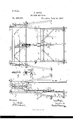
- Figure 1. is an end elevavation of the head-frame and one of the loadcarrying platforms; and Fig. 2 is a front elcvation, partially in section, of the same.
- Fig. 3 is a detached view of one of the hangers for supporting the elevating and reversing mechanism.
- Fig. 4 represents detached details of the cross-bars and hanger-connections.
- A represents the head of the hoisting-frame, which is formed of a section of girder or I beam, and provided with fourlegs, B, of gaspiping, connected to the head A by sockcts O, bolted to the head near its ends, as shown.
- These legs are set bracing outward in all direct-ions from the head A, so as to stand firmly, and will also be provided with feet B, having holes by which they may be fastened to the joist or floors on which the frame stands.
- the legs B will also be supported by cross-tie bars or braces a a, bolted across the legs, as shown.
- D D represent the guides for the'platforms, which willbe formed ofgas piping and secured at their upper ends to the head A by crossbars E, connected by clamps E to the head, as shown.
- the crossbars E are connected to the guides D by clips b, so that they can be easily connected to and disconnected from the head when the machine is to be moved or set up in another location.
- the sockets G are formed in one piece, with hangers G for supporting the main elevatingshaft F and the reversing-shaft G, the formation of these hangers being shown more clearly in Fig. 1.
- F is a cable-sheave fast upon the center of the shaft F and having ratchet-teeth e 0 formed upon both of its rims, theteeth on one rim being reversed from those on the other,so that they point in opposite directions.
- the shaft G is provided with two pawls, G G", the pawl G adapted to engage with the right -hand set of ratchet -teeth 6', and the other pawl, G adapted to engage with the left-hand set of teeth a, the pawls being so connected to the shaft G that only one is in operation at the same time, their action and functions being hereinafter explained.
- the legs B and shafts F G are arranged to be dis connected from the head A and set up again at any other point or moved from floor to floor during the progress of the building, the clips I) being connected by nuts having handles, so
- the caps cl and d by which the shaft F is held in the hangers Charo hinged to the frame of the hangers, so as to be easily turned over to release the shaft and permit it to be removed when themachine is to be taken down, or to admit of its replacement when the machine is to be set up again.
- the legs B are simply set up into the sockets O, the weight of the head and shafting and loads on the platforms being sufficient to hold it in place.
- the lower ends of the hangers (1 have small lugs h enclasping the braccsa a by which the hangers 0 between the lugs h, fit to prevent any side movement of the hangers, the hangers and head-frame being thus firmly united and prevented from displacement. Braces g will also be placed between the head A and the hangers G O to still further strengthen the frame.
- the cages or platform for carrying the loads to be elevated by this machine are formed of a gas or steam pipe frame, H, and adapted to run up and down between the guides D and supported in position betweenthe guides by guide rollers Two of these platforms will be employed to each machine, but as they are precisely alike only one is shown as being sufficient to illustrate theinvention.
- a plate, H is secured to support the upper parts of the hods K or other implements for containing the material to be elevated, the lower end of the handles K of the hods resting upon a foot board, H attached to the lower part of the frame H, as shown.
- One of the hods K is shown in position in Fig. 1, and the outlines in dotted lines of the same is shown in Fig.
- the plate H has projecting ends m and a projecting central part, m", to form cavities for the hods and to prevent them from being thrown from side to side of the platform.
- the footboard H is secured at its ends to the frame H by bars n, connected at one end to the bottom of the frame, and running outward beneath the foot-board and secured thereto by bolts 12*, the same bolts also securing the lower ends of the braces 12 the upper ends of the braces being secured by bolts nto the frame H, as shown.
- the foot-board is still further secured by a bar, M, bent at right angles, and secured beneath the foot-board by bolts t, and passing upward behind the frame and secured by its upper end to the cross-piece H of the frame H.
- the clamp for securing the cable P for hoisting the platforms will be secured.
- This clamp consists of a base, N, having a half-round upright channel corresponding to a channel in a cap, j'N, secured to the base N by a clampscrew, N", so that the cable when placed between the base and cap N N and the screw N set up the cable will be firmly clamped and held at any desired point.
- the cable will be long enough to reach from one of the platforms upward over the sheave F and down to the next platform when the building in which the machine is to be employed is completed; but in first using the machine (upon the second story of the building) the cable will be connected to the frames by the clamps at the proper point to enable one platform to be at the highest working point and the other at the lowest, and the surplus rope wound around the projecting ends 10 of the braces H which are formed curved, as shown, for that purpose. Then, as the building progresses the head-frame will be moved from story to story, the guides lengthened, and the cable correspondingly lengthened.
- the operation. is very simple and a detailed- The head-frame will be properly set with i the platforms and cable in position. If the load to be elevated is on the right-hand platform, as viewed from Fig. 1, the shaft G will be turned so as to cause the pawl G to engage with the ratchet-teeth e, as in Fig. 1, so that when the load is being elevated the pawl acts as a safety appliance to prevent the load running down if the crank on the shaft F should for any reason be released. Then when the other platform is to be elevated, the other pawl, G, will be thrown into contact with the ratchetteeth 6 to perform the same function for the other platform.
- the sheave F will be provided with ribs to cause the cable to be held with greater power and to prevent slipping.
- a hoisting-machine coupling the headframe consisting of the head A, having combined hangers and sockets O O, removable legs B, which support said sockets, shaft F, carrying combined sheave and ratchet-wheel F and supported in said hangers, and bars E, adapted to support the platform-guides D, all of said parts being detachably connected, whereby said head-frame is capable of being easily set up or taken down for transportation, substantially as and for the purpose set forth. 2.
- a hoistingmachine the combination, with a head-frame having cross-bars E and shaft F, supporting a combined sheave and ratchet-wheel, F of the guides D, supported in an upright position by clamps connecting them to said cross-bars, platforms consisting of frames H, foot-board's H and bod-support H and adapted to be alternately raised and lowered by cable P, connected to said platforms, and passing from one of said platforms to the other over said sheave, and a shaft, G, carrying pawls G G adapted to engage alternately with the teeth of said ratchet-wheel, substantially as and for the purpose set forth.
Landscapes
- Engineering & Computer Science (AREA)
- Structural Engineering (AREA)
- Civil Engineering (AREA)
- Transportation (AREA)
- Automation & Control Theory (AREA)
- Lift-Guide Devices, And Elevator Ropes And Cables (AREA)
Description
(No Model.)
J. BOYD.
HOISTING MACHINE.
No. 366,299. n Patented July 12,1887.
r jfig 3 N PETERS. Phmoinhograplvur, Washinglon, D, C.
Fries.
PATENT JAMES BOYD, OF ST. PAUL, MINNESOTA.
HOISTING- MACHINE.
EPECIFICATION forming part of Letters Patent No. 366,299, dated July 12, 1887.
Application filed May 2, 1887. Serial No. 286,880. No model.)
To ail whom it may concern:
Be it known that I, JAMES BOYD, a citizen of the United States, residing at St. Paul, in the county of Ramsey and State of Minnesota, have invented certain new and useful Improvements in Hoistinglliachines, of which the following is a specification.
This invention relates to that class of machines employed for elevating brick, mortar, and other building material during the process of the erection of buildings; and it con sists in the construction, combination, and arrangement of parts, as hereinafter shown and described, and specifically pointed out in the claims.
In the drawings, Figure 1.is an end elevavation of the head-frame and one of the loadcarrying platforms; and Fig. 2 is a front elcvation, partially in section, of the same. Fig. 3 is a detached view of one of the hangers for supporting the elevating and reversing mechanism. Fig. 4 represents detached details of the cross-bars and hanger-connections.
A represents the head of the hoisting-frame, which is formed of a section of girder or I beam, and provided with fourlegs, B, of gaspiping, connected to the head A by sockcts O, bolted to the head near its ends, as shown. These legs are set bracing outward in all direct-ions from the head A, so as to stand firmly, and will also be provided with feet B, having holes by which they may be fastened to the joist or floors on which the frame stands. The legs B will also be supported by cross-tie bars or braces a a, bolted across the legs, as shown.
D D represent the guides for the'platforms, which willbe formed ofgas piping and secured at their upper ends to the head A by crossbars E, connected by clamps E to the head, as shown. The crossbars E are connected to the guides D by clips b, so that they can be easily connected to and disconnected from the head when the machine is to be moved or set up in another location. The sockets G are formed in one piece, with hangers G for supporting the main elevatingshaft F and the reversing-shaft G, the formation of these hangers being shown more clearly in Fig. 1.
From the center of the head A another hanger, C is suspended to support the cenbe covered with a cap, (P, to protect them from the dust and dirt.
F is a cable-sheave fast upon the center of the shaft F and having ratchet-teeth e 0 formed upon both of its rims, theteeth on one rim being reversed from those on the other,so that they point in opposite directions.
The shaft G is provided with two pawls, G G", the pawl G adapted to engage with the right -hand set of ratchet -teeth 6', and the other pawl, G adapted to engage with the left-hand set of teeth a, the pawls being so connected to the shaft G that only one is in operation at the same time, their action and functions being hereinafter explained. The legs B and shafts F G are arranged to be dis connected from the head A and set up again at any other point or moved from floor to floor during the progress of the building, the clips I) being connected by nuts having handles, so
as to be easily removed, and the bolts for connecting the braces a a to the legs B being likewise secured by handled nutsfor the same purpose.
The caps cl and d, by which the shaft F is held in the hangers Charo hinged to the frame of the hangers, so as to be easily turned over to release the shaft and permit it to be removed when themachine is to be taken down, or to admit of its replacement when the machine is to be set up again. The legs B are simply set up into the sockets O, the weight of the head and shafting and loads on the platforms being sufficient to hold it in place. The lower ends of the hangers (1 have small lugs h enclasping the braccsa a by which the hangers 0 between the lugs h, fit to prevent any side movement of the hangers, the hangers and head-frame being thus firmly united and prevented from displacement. Braces g will also be placed between the head A and the hangers G O to still further strengthen the frame.
The cages or platform for carrying the loads to be elevated by this machine are formed of a gas or steam pipe frame, H, and adapted to run up and down between the guides D and supported in position betweenthe guides by guide rollers Two of these platforms will be employed to each machine, but as they are precisely alike only one is shown as being sufficient to illustrate theinvention. Across the upper part of the frame A a plate, H is secured to support the upper parts of the hods K or other implements for containing the material to be elevated, the lower end of the handles K of the hods resting upon a foot board, H attached to the lower part of the frame H, as shown. One of the hods K is shown in position in Fig. 1, and the outlines in dotted lines of the same is shown in Fig. 2 to illustrate how the hods are supported. The plate H has projecting ends m and a projecting central part, m", to form cavities for the hods and to prevent them from being thrown from side to side of the platform. The footboard H is secured at its ends to the frame H by bars n, connected at one end to the bottom of the frame, and running outward beneath the foot-board and secured thereto by bolts 12*, the same bolts also securing the lower ends of the braces 12 the upper ends of the braces being secured by bolts nto the frame H, as shown. At its center the foot-board is still further secured by a bar, M, bent at right angles, and secured beneath the foot-board by bolts t, and passing upward behind the frame and secured by its upper end to the cross-piece H of the frame H. To the rear of this center bar, M, the clamp for securing the cable P for hoisting the platforms will be secured. This clamp consists of a base, N, having a half-round upright channel corresponding to a channel in a cap, j'N, secured to the base N by a clampscrew, N", so that the cable when placed between the base and cap N N and the screw N set up the cable will be firmly clamped and held at any desired point.
The cable will be long enough to reach from one of the platforms upward over the sheave F and down to the next platform when the building in which the machine is to be employed is completed; but in first using the machine (upon the second story of the building) the cable will be connected to the frames by the clamps at the proper point to enable one platform to be at the highest working point and the other at the lowest, and the surplus rope wound around the projecting ends 10 of the braces H which are formed curved, as shown, for that purpose. Then, as the building progresses the head-frame will be moved from story to story, the guides lengthened, and the cable correspondingly lengthened.
The operation. is very simple and a detailed- The head-frame will be properly set with i the platforms and cable in position. If the load to be elevated is on the right-hand platform, as viewed from Fig. 1, the shaft G will be turned so as to cause the pawl G to engage with the ratchet-teeth e, as in Fig. 1, so that when the load is being elevated the pawl acts as a safety appliance to prevent the load running down if the crank on the shaft F should for any reason be released. Then when the other platform is to be elevated, the other pawl, G, will be thrown into contact with the ratchetteeth 6 to perform the same function for the other platform. The sheave F will be provided with ribs to cause the cable to be held with greater power and to prevent slipping.
Having thus described my invention, what I claim as new is v 1. A hoisting-machine coupling, the headframe consisting of the head A, having combined hangers and sockets O O, removable legs B, which support said sockets, shaft F, carrying combined sheave and ratchet-wheel F and supported in said hangers, and bars E, adapted to support the platform-guides D, all of said parts being detachably connected, whereby said head-frame is capable of being easily set up or taken down for transportation, substantially as and for the purpose set forth. 2. The combination, in a hoisting-machine, of head A, having combined sockets and hangers G (3 attached thereto, legs B, adapted to be set into said sockets to support said head, notched brace-bars a a connecting said legs and supporting the lower ends of said hangers by lugs h h, shaft F, journaled removably in said hangers and having combined sheave and ratchet-wheel Fiattached thereto, and shaft G, journaled in said hangers and carrying pawls G G adapted to alternately engage with the teeth of said ratchet-wheel to form a safety appliance in connection with said sheave, substantially as and for the purpose set forth.
3. In a hoistingmachine, the combination, with a head-frame having cross-bars E and shaft F, supporting a combined sheave and ratchet-wheel, F of the guides D, supported in an upright position by clamps connecting them to said cross-bars, platforms consisting of frames H, foot-board's H and bod-support H and adapted to be alternately raised and lowered by cable P, connected to said platforms, and passing from one of said platforms to the other over said sheave, and a shaft, G, carrying pawls G G adapted to engage alternately with the teeth of said ratchet-wheel, substantially as and for the purpose set forth.
In testimony whereof I have hereunto set my hand in the presence of two subscribing witnesses.
. JAMES BOYD.
Witnesses:
C. N. WOODWARI), H. S. WEBSTER.
ICO
Publications (1)
| Publication Number | Publication Date |
|---|---|
| US366299A true US366299A (en) | 1887-07-12 |
Family
ID=2435320
Family Applications (1)
| Application Number | Title | Priority Date | Filing Date |
|---|---|---|---|
| US366299D Expired - Lifetime US366299A (en) | Hoisting-machine |
Country Status (1)
| Country | Link |
|---|---|
| US (1) | US366299A (en) |
Cited By (1)
| Publication number | Priority date | Publication date | Assignee | Title |
|---|---|---|---|---|
| US2833422A (en) * | 1950-12-28 | 1958-05-06 | Ferwerda Ray | Telescopic boom |
-
0
- US US366299D patent/US366299A/en not_active Expired - Lifetime
Cited By (1)
| Publication number | Priority date | Publication date | Assignee | Title |
|---|---|---|---|---|
| US2833422A (en) * | 1950-12-28 | 1958-05-06 | Ferwerda Ray | Telescopic boom |
Similar Documents
| Publication | Publication Date | Title |
|---|---|---|
| US366299A (en) | Hoisting-machine | |
| US182380A (en) | Improvement in portable elevators | |
| US485463A (en) | Builder s scaffold | |
| US437935A (en) | Movable scaffold | |
| US837006A (en) | Portable scaffold. | |
| US295269A (en) | miller | |
| US1085207A (en) | Portable fire-escape. | |
| US300887A (en) | Adjustable trestle | |
| US160390A (en) | Improvement in swings | |
| US265012A (en) | Brick-elevator | |
| US218680A (en) | Improvement in fire-escapes | |
| US1083508A (en) | Elevator for building materials. | |
| US805524A (en) | Adjustable standard. | |
| US411363A (en) | Scaffold | |
| US391854A (en) | Swinging scaffold | |
| US1127445A (en) | Scaffolding device. | |
| US118783A (en) | Improvement in brick and mortar-elevators | |
| US502484A (en) | Extension fire-ladder | |
| US150005A (en) | Improvement in scaffolds | |
| US1211318A (en) | Scaffold. | |
| US1187060A (en) | Scaffold. | |
| US494328A (en) | Hoisting-machine | |
| US583034A (en) | Benjamin f | |
| US348359A (en) | Adjustable scaffold | |
| US464177A (en) | Scaffold |