US3649867A - Image display device utilizing a target composed of discrete phosphors - Google Patents
Image display device utilizing a target composed of discrete phosphors Download PDFInfo
- Publication number
- US3649867A US3649867A US831083A US3649867DA US3649867A US 3649867 A US3649867 A US 3649867A US 831083 A US831083 A US 831083A US 3649867D A US3649867D A US 3649867DA US 3649867 A US3649867 A US 3649867A
- Authority
- US
- United States
- Prior art keywords
- phosphor
- phosphors
- visible
- display device
- emitting
- Prior art date
- Legal status (The legal status is an assumption and is not a legal conclusion. Google has not performed a legal analysis and makes no representation as to the accuracy of the status listed.)
- Expired - Lifetime
Links
- OAICVXFJPJFONN-UHFFFAOYSA-N Phosphorus Chemical compound [P] OAICVXFJPJFONN-UHFFFAOYSA-N 0.000 claims abstract description 55
- 230000005684 electric field Effects 0.000 claims abstract description 7
- 238000010894 electron beam technology Methods 0.000 claims description 15
- 238000000576 coating method Methods 0.000 claims description 6
- 239000000463 material Substances 0.000 claims description 4
- SIWVEOZUMHYXCS-UHFFFAOYSA-N oxo(oxoyttriooxy)yttrium Chemical compound O=[Y]O[Y]=O SIWVEOZUMHYXCS-UHFFFAOYSA-N 0.000 claims description 3
- 229910052688 Gadolinium Inorganic materials 0.000 claims description 2
- 230000003213 activating effect Effects 0.000 claims description 2
- 230000015572 biosynthetic process Effects 0.000 claims description 2
- UIWYJDYFSGRHKR-UHFFFAOYSA-N gadolinium atom Chemical compound [Gd] UIWYJDYFSGRHKR-UHFFFAOYSA-N 0.000 claims description 2
- 239000000758 substrate Substances 0.000 claims description 2
- 229910009372 YVO4 Inorganic materials 0.000 claims 1
- 238000010791 quenching Methods 0.000 abstract description 7
- 230000007246 mechanism Effects 0.000 abstract description 6
- 230000000171 quenching effect Effects 0.000 abstract description 6
- 238000000034 method Methods 0.000 description 7
- 230000008569 process Effects 0.000 description 6
- 238000000926 separation method Methods 0.000 description 5
- 230000000694 effects Effects 0.000 description 3
- 239000011521 glass Substances 0.000 description 3
- BQCADISMDOOEFD-UHFFFAOYSA-N Silver Chemical compound [Ag] BQCADISMDOOEFD-UHFFFAOYSA-N 0.000 description 2
- 239000011248 coating agent Substances 0.000 description 2
- 239000003086 colorant Substances 0.000 description 2
- 230000008878 coupling Effects 0.000 description 2
- 238000010168 coupling process Methods 0.000 description 2
- 238000005859 coupling reaction Methods 0.000 description 2
- 238000004020 luminiscence type Methods 0.000 description 2
- 229910052709 silver Inorganic materials 0.000 description 2
- 239000004332 silver Substances 0.000 description 2
- 235000010627 Phaseolus vulgaris Nutrition 0.000 description 1
- 244000046052 Phaseolus vulgaris Species 0.000 description 1
- 238000010521 absorption reaction Methods 0.000 description 1
- 230000001133 acceleration Effects 0.000 description 1
- 230000004913 activation Effects 0.000 description 1
- 238000005452 bending Methods 0.000 description 1
- 230000009286 beneficial effect Effects 0.000 description 1
- 238000006243 chemical reaction Methods 0.000 description 1
- 239000004020 conductor Substances 0.000 description 1
- 238000010276 construction Methods 0.000 description 1
- 230000007547 defect Effects 0.000 description 1
- 238000000151 deposition Methods 0.000 description 1
- 229940047127 fiore Drugs 0.000 description 1
- 238000002955 isolation Methods 0.000 description 1
- 229910052751 metal Inorganic materials 0.000 description 1
- 239000002184 metal Substances 0.000 description 1
- 230000035515 penetration Effects 0.000 description 1
- 239000002985 plastic film Substances 0.000 description 1
- 229920006255 plastic film Polymers 0.000 description 1
- 230000001360 synchronised effect Effects 0.000 description 1
Images
Classifications
-
- H—ELECTRICITY
- H01—ELECTRIC ELEMENTS
- H01J—ELECTRIC DISCHARGE TUBES OR DISCHARGE LAMPS
- H01J29/00—Details of cathode-ray tubes or of electron-beam tubes of the types covered by group H01J31/00
- H01J29/46—Arrangements of electrodes and associated parts for generating or controlling the ray or beam, e.g. electron-optical arrangement
- H01J29/80—Arrangements for controlling the ray or beam after passing the main deflection system, e.g. for post-acceleration or post-concentration, for colour switching
- H01J29/803—Arrangements for controlling the ray or beam after passing the main deflection system, e.g. for post-acceleration or post-concentration, for colour switching for post-acceleration or post-deflection, e.g. for colour switching
-
- B—PERFORMING OPERATIONS; TRANSPORTING
- B82—NANOTECHNOLOGY
- B82Y—SPECIFIC USES OR APPLICATIONS OF NANOSTRUCTURES; MEASUREMENT OR ANALYSIS OF NANOSTRUCTURES; MANUFACTURE OR TREATMENT OF NANOSTRUCTURES
- B82Y10/00—Nanotechnology for information processing, storage or transmission, e.g. quantum computing or single electron logic
-
- H—ELECTRICITY
- H01—ELECTRIC ELEMENTS
- H01J—ELECTRIC DISCHARGE TUBES OR DISCHARGE LAMPS
- H01J29/00—Details of cathode-ray tubes or of electron-beam tubes of the types covered by group H01J31/00
- H01J29/02—Electrodes; Screens; Mounting, supporting, spacing or insulating thereof
- H01J29/10—Screens on or from which an image or pattern is formed, picked up, converted or stored
- H01J29/18—Luminescent screens
- H01J29/26—Luminescent screens with superimposed luminescent layers
Definitions
- ABSTRACT The specification describes a single-gun television receiving tube in which color selection is obtained by direct modulation of the phosphor target. Associated with the three-color array of phosphors is an electrode grid which enables all phosphor regions of one color to be exposed simultaneously to an electric field. Via a field quenching mechanism emission from those regions selectively exposed to the field is prevented while the phosphor regions for the color corresponding to the input information emit.
- the target is composed of discrete regions of three color phosphors in juxtaposition as in a conventional tube.
- the single beam sequentially scans all three color phosphors while the color selection process is independently carried'out.
- the latter is achieved by locally a plying a field to all regions of one color so that the luminescent process in those regions is preferentially modulated. If the regions representing two colors are simultaneously quenched by the fieldonly one color will emit.
- color selection is made independent of the scanning beam through the application of localized fields directly to the target.
- the field is selectively applied simultaneously to all phosphor dots of a given color through a grid of electrodes associated with each group of phosphor color regions.
- Color intensity information is supplied by modulating the cathode-target voltage in the usual manner.
- the color intensity information can be transmitted in time division with each division corresponding to a frame period.
- the appropriate phosphor region is switched on by removing its quenching field and a single color image is produced.
- the remaining two color images follow in sequence.
- the inability of the eye to discern changes over a frame period permits an apparent reconstitution of the image in full color.
- the use of time division in transmitting color television signals is well known and the inability of the eye to resolve the color of a single frame has been established.
- the aesthetic appeal of images formed using this system is indistinguishable from that formed by simultaneous activation of three color phosphors.
- the isolation of the color selection process from the electron beam effects dramatic changes in the tube.
- the shadow mask is eliminated. Errors in beam deflection due to inherent tube defects or due to spurious magnetic fields are no longer of consequence.
- the converging lens, and the dynamic focusing deflection circuits associated with it, are unnecessary.
- the target face requires division between color regions only in the plane normal to the beam scanning direction. Thus stripes may be substituted for the dot trios in conventional use. It is however necessary to have precise registration between the phosphor regions and their associated electrical contacts so as to permit the controlled application of localized fields.
- the mechanism for modulation of the target independent of the beam relies on a field-quenching phenomenon whereby a phosphor exposed to an electric field'is rendered incapable of luminescence.
- the phosphor is photon coupled to the electron beam so that the visible display is produced by secondary photon emission. Structurally this means that an ultraviolet cathodoluminescent coating is interspersed between the phosphor and the beam so as to absorb the bulk of the bean electrons.
- the cathodoluminescent coating is a UV emitting phosphor and visible display phosphor is a UV excited photoluminescent phosphor.
- the UV coupling mechanism appears to be most practical at present although other possibilities exist.
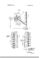
- FIG. 1 is a schematic view of a receiving tube having conventional components except for the target;
- FIG. 2A is a plan view, in section, of one embodiment of a target embodying the principles of the invention.
- FIG. 2B is'a view similar to FIG. 2A illustrating an alternative embodiment.
- the receiving tube 10 of FIG. 1 employs a standard cathode-ray gun in which, in an exemplary embodiment, the video signal 11 is impressed on the control grids associated with grid control circuits 13. These circuits appropriately bias grids 14-17 for beam brightness control, focus and acceleration in the conventional manner.
- X-Y deflectors l8 and 19 are operated by deflection circuits 20 to provide the usual horizontal raster.
- the target 21 embodies the principles of the invention to control the color selection process. This is accomplished by a switching network 22 which is synchronized with the video signal 11.
- the target 21 is shown in detail in the embodiments of FIGS. 2A and 2B.
- the target is shown in a sectional plan view. This view represents only a small region of the target.
- the tube face 30 is the conventional glass envelope. Deposited on the inside of the tube face are a series of electrode strips 31, 32, and 33 each of which extends over the height dimension of the tube. Although the electrode strips are identical they are grouped in three groups, each group representing one of the three conventional phosphor colors. Each group shares a common electrode so that all electrode strips associated with a given color phosphor can be simultaneously electrically energized. The phosphors associated with these strips are shown at 41, 42 and 43. Counter electrodes 51, 52 and 53 are applied to form a sandwich structure with the phosphor disposed between metal film electrodes.
- electrodes 31 and 51 must be connected to a common terminal, likewise with electrodes 32 and 52, and 33 and 53. In each case however one electrode can be a common ground. Accordingly if electrodes 51 to 53 are segregated, electrodes 31 to 33 can comprise a continuous electrode film. In the same way electrodes 51 to 53 may comprise one continuous electrode although the particular structure of FIG. 2A does not admit of this.
- the target functions via the quenching mechanism described above.
- the quenching mechanism described above.
- the following specific structure is suggested.
- the glass envelope 30 is a standard vacuum tube envelope.
- the electrodes 3l33 can be any conductive material which is largely transparent to the emitting wavelength of the visible phosphors, e.g., SnO
- the thickness may be a few tenths of a micron to 20 microns or more depending upon the resolution and absorption tolerances.
- the visible emitting phosphors ll-43 are conventional red, green and blue phosphors. Exemplary materials are: red YVO.,:Eu green ZnCdSzAg, blue ZnS:Ag. All of these can be activated by ultraviolet energy, a property common to most conventional phosphors.
- the thickness of the phosphor coatings is conventional, e.g., 5 to lOO L.
- the counter electrodes 51-53 must be transparent to ultraviolet light.
- a thin (0.1 to 0.5 silver film is adequate for this purpose (silver has a "window” at 3.8 e.v.).
- SnO could be used.
- a useful ultraviolet emitting phosphor for layer 60 is gadolinium-doped yttrium oxide (1 to moi Gd). This material emits efficiently at 3.100 A.
- a film thickness in the range of 5 to 50 will have an adequate cross section to capture [0 to kv. electrons.
- the quenching field necessary to give a visible-light modulation ratio of 10 to l is of the order of i0 volts/cm., or 1 volt per micron ofphosphor thickness.
- FIG. 2B An alternative embodiment that is functionally very similar to that of FIG. 2A is shown in FIG. 2B.
- the elements with primed numbers correspond directly to their unprimed counterparts in FIG. 2A.
- a significant distinction between the two structures is the physical separation of the two phosphor coatings by the glass faceplate This has beneficial implications in the processing of the target.
- the processes for depositing the UV and visible phosphors can be totally independent.
- the UV phosphor can be deposited in a continuous layer.
- the electrical separation of the visible phosphor from the electron beam which is an important feature of this structure, is especially complete in this embodiment.
- this target structure be independent of the faceplate suggests that the sandwich structure containing the visible phosphor can be made independently of the faceplate 30' and its assocrated phosphor For example a plastic film carrying the array of visible phosphors can be separately fabricated and then applied to the faceplate 30'.
- the image display device described above has the added feature of being operable in a black and white mode and thus satisfies the compatability requirement of current video receivers.
- a color image display device comprising an evacuated envelope, a phosphor screen disposed within said envelope, means for forming an electron beam adapted to scan the phosphor screen.
- the phosphor screen comprising a monolithic array of discrete photosensitive visible phosphors substantially covering the screen, the discrete phosphors emitting at more than one visible wavelength so as to permit the formation of a multicolored image, electrode means associated with each discrete phosphor for exposing that phosphor to an electric field, the electrode means comprising an electrode array in which the electrodes associated with phosphors emitting at one wavelength are connected together while the electrodes associated with phos hors emitting at another wavelength are connected toget er so that the phosphors emitting at a common wavelength can be selectively exposed to an electric field, and a cathodoluminescent phosphor adjacent to the visible phosphors, the cathodoluminescent phosphor comprising a material emitting at a wavelength capable of activating the visible phosphor.
- the display device of claim 3 wherein the cathodoluminescent phosphor comprises yttrium oxide doped with l to L0 76 gadolinium.
- the display device of claim 4 further including means as sociated with the electrode means for selectively applying a field of the order of 5 to 100 volts to the visible phosphors.
- the device of claim 1 wherein the visible phosphors emitting at more than one wavelength comprise red-, green-, and blue-emitting phosphors.
- the visible phosphors comprise YVO :EU, ZnCdSzAg, and ZnSzAg.
Landscapes
- Engineering & Computer Science (AREA)
- Chemical & Material Sciences (AREA)
- Nanotechnology (AREA)
- Physics & Mathematics (AREA)
- Mathematical Physics (AREA)
- Theoretical Computer Science (AREA)
- Crystallography & Structural Chemistry (AREA)
- Cathode-Ray Tubes And Fluorescent Screens For Display (AREA)
Abstract
The specification describes a single-gun television receiving tube in which color selection is obtained by direct modulation of the phosphor target. Associated with the three-color array of phosphors is an electrode grid which enables all phosphor regions of one color to be exposed simultaneously to an electric field. Via a field quenching mechanism emission from those regions selectively exposed to the field is prevented while the phosphor regions for the color corresponding to the input information emit.
Description
United States Patent Chester et a1.
[451 Mar. 14, 1972 IMAGE DISPLAY DEVICE UTILIZING A TARGET COMPOSED OF DISCRETE PHOSPHORS Inventors: Arthur N. Chester, Murray Hill; Dawon Kahng, Bridgewater Township, Somerset County; Bernard B. Kosicki, New Providence, all of NJ.
Bell Telephone Laboratories, Incorporated, Murray Hill, NJ.
Filed: June 6, 1969 Appl. No.: 831,083
Assignee:
U.S. CL ..3l5/12, 313/92 Int. Cl. ..I'I0lj 29/41 FieldofSearch ..3l5/l0, l2,2l;313/92 References Cited UNITED STATES PATENTS 9/1957 Zworykin ..315/ 12X ELECTRQN BEAM 61 SCAN 2,861,206 11/1958 Fiore ..313/92 X 2,875,875 2/1959 Kruper..... 3,360,674 12/1967 Mikus ..313/92 X Primary ExaminerRodney D. Bennett, Jr. Assistant Examiner-J. M. Potenza AttorneyR. J. Guenther and Arthur J. Torsiglieri [57] ABSTRACT The specification describes a single-gun television receiving tube in which color selection is obtained by direct modulation of the phosphor target. Associated with the three-color array of phosphors is an electrode grid which enables all phosphor regions of one color to be exposed simultaneously to an electric field. Via a field quenching mechanism emission from those regions selectively exposed to the field is prevented while the phosphor regions for the color corresponding to the input information emit.
8 Claims, 3 Drawing Figures PATENTEDMAR 14 I972 (5R! D CONTROL C l RCUITS DEFLECTION Cl RCUI TS A. N. CHESTER uwe/vrons 0. KAHNG B. B. KOS/CK/ COLOR SELECTOR NETWORK ELECTRQN BEAM 6| ATTORNEY IMAGE DISPLAY DEVICE UTILIZING A TARGET COMPOSED OFDISCRETE PHOSPHORS This inventionrelates to an improved electro-optic conversion tube for displaying light images.
Conventional devices for displaying, light images such as television receiver tubes rely on the light-producing effect of a modulated electron beam scanninga cathodoluminescent target. In such a system it' is vital that the modulation signal be closely synchronizedwith the scanning signals. When'a color signal is added it becomes necessary to maintain this synchronizationwiththe added requirement of precise physical alignment between the-electron beam andthe appropriate series of color'dots on the tube face. With the realization that three such electron beams must" function simultaneously in this fashion, the enormous complexity of the existing commercial version of the television-receiver tube can be appreciated.
Efforts to reduce the complexity ofthe tube and increase its reliabilityhave been intense and most often directed toward producing a single electron gun tube fordisplaying color images.
One of these efforts, which has been developed to a commercial embodiment, relies on bending the electron beam so as to impinge on the target at an angle. The incident angle determines which of the three color dots the beam will strike. Again, this requires critical physical alignment of the beam and the target. It would be desirable to-have the color selection process independent of the electron beam. This would eliminate the need for exacting physical alignment between the beam andthe target.
These advantages are at least partially obtainable in the image display device of the invention. In this device the target is composed of discrete regions of three color phosphors in juxtaposition as in a conventional tube. However, in contrast with-the operation of the conventional tube, the single beam sequentially scans all three color phosphors while the color selection process is independently carried'out. The latter is achieved by locally a plying a field to all regions of one color so that the luminescent process in those regions is preferentially modulated. If the regions representing two colors are simultaneously quenched by the fieldonly one color will emit. By this means, color selection is made independent of the scanning beam through the application of localized fields directly to the target. The field is selectively applied simultaneously to all phosphor dots of a given color through a grid of electrodes associated with each group of phosphor color regions. Color intensity information is supplied by modulating the cathode-target voltage in the usual manner.
Various modes of operation are possible using the concept just described. For example, the color intensity information can be transmitted in time division with each division corresponding to a frame period. The appropriate phosphor region is switched on by removing its quenching field and a single color image is produced. The remaining two color images follow in sequence. The inability of the eye to discern changes over a frame period permits an apparent reconstitution of the image in full color. The use of time division in transmitting color television signals is well known and the inability of the eye to resolve the color of a single frame has been established. The aesthetic appeal of images formed using this system is indistinguishable from that formed by simultaneous activation of three color phosphors.
The isolation of the color selection process from the electron beam effects dramatic changes in the tube. The shadow mask is eliminated. Errors in beam deflection due to inherent tube defects or due to spurious magnetic fields are no longer of consequence. The converging lens, and the dynamic focusing deflection circuits associated with it, are unnecessary. The target face requires division between color regions only in the plane normal to the beam scanning direction. Thus stripes may be substituted for the dot trios in conventional use. It is however necessary to have precise registration between the phosphor regions and their associated electrical contacts so as to permit the controlled application of localized fields.
The mechanism for modulation of the target independent of the beam relies on a field-quenching phenomenon whereby a phosphor exposed to an electric field'is rendered incapable of luminescence.
To obtain efficient field quenching it has been found desirable to isolate the phosphor from direct incidence of the electron beam. If the electron beam falls directly on the phosphor, the penetration depth of electrons is usually too large to effect efficient field modulation of luminescence. To overcome this, the phosphor is photon coupled to the electron beam so that the visible display is produced by secondary photon emission. Structurally this means that an ultraviolet cathodoluminescent coating is interspersed between the phosphor and the beam so as to absorb the bulk of the bean electrons.
If the photon coupling mechanism relies on ultraviolet photons, the cathodoluminescent coating is a UV emitting phosphor and visible display phosphor is a UV excited photoluminescent phosphor. The UV coupling mechanism appears to be most practical at present although other possibilities exist.
From the foregoing general discussion it is evident that the separation of the color selection function from the electron beam drastically changes the design characteristics of the television receiving tube. The simple, economic construction made possible by the use of directly modulating the target to obtain the color selection function may represent a considerable advance in the art.
The invention is set forth in greater detail in the following specific description.
In the drawing:
FIG. 1 is a schematic view of a receiving tube having conventional components except for the target;
FIG. 2A is a plan view, in section, of one embodiment of a target embodying the principles of the invention; and
FIG. 2B is'a view similar to FIG. 2A illustrating an alternative embodiment.
The receiving tube 10 of FIG. 1 employs a standard cathode-ray gun in which, in an exemplary embodiment, the video signal 11 is impressed on the control grids associated with grid control circuits 13. These circuits appropriately bias grids 14-17 for beam brightness control, focus and acceleration in the conventional manner. X-Y deflectors l8 and 19 are operated by deflection circuits 20 to provide the usual horizontal raster. The target 21 embodies the principles of the invention to control the color selection process. This is accomplished by a switching network 22 which is synchronized with the video signal 11.
The target 21 is shown in detail in the embodiments of FIGS. 2A and 2B.
In the embodiment of FIG. 2A the target is shown in a sectional plan view. This view represents only a small region of the target. The tube face 30 is the conventional glass envelope. Deposited on the inside of the tube face are a series of electrode strips 31, 32, and 33 each of which extends over the height dimension of the tube. Although the electrode strips are identical they are grouped in three groups, each group representing one of the three conventional phosphor colors. Each group shares a common electrode so that all electrode strips associated with a given color phosphor can be simultaneously electrically energized. The phosphors associated with these strips are shown at 41, 42 and 43. Counter electrodes 51, 52 and 53 are applied to form a sandwich structure with the phosphor disposed between metal film electrodes. To confine the application of the field to those sandwich structures having a common phosphor color either or both electrodes 31 and 51 must be connected to a common terminal, likewise with electrodes 32 and 52, and 33 and 53. In each case however one electrode can be a common ground. Accordingly if electrodes 51 to 53 are segregated, electrodes 31 to 33 can comprise a continuous electrode film. In the same way electrodes 51 to 53 may comprise one continuous electrode although the particular structure of FIG. 2A does not admit of this.
.Each phosphor sandwich is then covered with a cathodoluminescent phosphor 60 to provide separation between the electron beam and the visible phosphors. This layer is common to all of the strips. The electron beam, which scans in the direction indicated, is shown schematically by arrow 61. It should be pointed out that FlG. 2A describes the essential elements of the structure. Various procedures for fabricating this or equivalent structures will occur to those skilled in the art.
The target functions via the quenching mechanism described above. As an illustrative embodiment. the following specific structure is suggested.
The glass envelope 30 is a standard vacuum tube envelope. The electrodes 3l33 can be any conductive material which is largely transparent to the emitting wavelength of the visible phosphors, e.g., SnO The thickness may be a few tenths of a micron to 20 microns or more depending upon the resolution and absorption tolerances. The visible emitting phosphors ll-43 are conventional red, green and blue phosphors. Exemplary materials are: red YVO.,:Eu green ZnCdSzAg, blue ZnS:Ag. All of these can be activated by ultraviolet energy, a property common to most conventional phosphors. The thickness of the phosphor coatings is conventional, e.g., 5 to lOO L. The counter electrodes 51-53 must be transparent to ultraviolet light. A thin (0.1 to 0.5 silver film is adequate for this purpose (silver has a "window" at 3.8 e.v.). Also SnO, could be used. A useful ultraviolet emitting phosphor for layer 60 is gadolinium-doped yttrium oxide (1 to moi Gd). This material emits efficiently at 3.100 A. A film thickness in the range of 5 to 50 will have an adequate cross section to capture [0 to kv. electrons. The quenching field necessary to give a visible-light modulation ratio of 10 to l is of the order of i0 volts/cm., or 1 volt per micron ofphosphor thickness.
An alternative embodiment that is functionally very similar to that of FIG. 2A is shown in FIG. 2B. In FIG. 2B the elements with primed numbers correspond directly to their unprimed counterparts in FIG. 2A. A significant distinction between the two structures is the physical separation of the two phosphor coatings by the glass faceplate This has beneficial implications in the processing of the target. For example the processes for depositing the UV and visible phosphors can be totally independent. The UV phosphor can be deposited in a continuous layer. For good resolution it may be advantageous to limit the thickness of the faceplate 30 or to provide a separate faceplate for physical protection of the tube. It is evident that the electrical separation of the visible phosphor from the electron beam, which is an important feature of this structure, is especially complete in this embodiment. it may be that the thermal separation inherent in this arrangement is important also. The suggestion made above that this target structure be independent of the faceplate suggests that the sandwich structure containing the visible phosphor can be made independently of the faceplate 30' and its assocrated phosphor For example a plastic film carrying the array of visible phosphors can be separately fabricated and then applied to the faceplate 30'.
it should be pointed out that the image display device described above has the added feature of being operable in a black and white mode and thus satisfies the compatability requirement of current video receivers.
What is claimed is:
l. A color image display device comprising an evacuated envelope, a phosphor screen disposed within said envelope, means for forming an electron beam adapted to scan the phosphor screen. the phosphor screen comprising a monolithic array of discrete photosensitive visible phosphors substantially covering the screen, the discrete phosphors emitting at more than one visible wavelength so as to permit the formation of a multicolored image, electrode means associated with each discrete phosphor for exposing that phosphor to an electric field, the electrode means comprising an electrode array in which the electrodes associated with phosphors emitting at one wavelength are connected together while the electrodes associated with phos hors emitting at another wavelength are connected toget er so that the phosphors emitting at a common wavelength can be selectively exposed to an electric field, and a cathodoluminescent phosphor adjacent to the visible phosphors, the cathodoluminescent phosphor comprising a material emitting at a wavelength capable of activating the visible phosphor.
2. The display device of claim I wherein a transparent substrate is interposed between the visible phosphors and their associated electrode means. and the cathodoluminescent phosphor.
3. The device of claim i wherein the cathodoluminescent phosphor emits in the ultraviolet.
t. The display device of claim 3 wherein the cathodoluminescent phosphor comprises yttrium oxide doped with l to L0 76 gadolinium.
S. The display device of claim 1 wherein the thickness of the visible phosphor coatings is in the range of5 to g.
6. The display device of claim 4 further including means as sociated with the electrode means for selectively applying a field of the order of 5 to 100 volts to the visible phosphors The device of claim 1 wherein the visible phosphors emitting at more than one wavelength comprise red-, green-, and blue-emitting phosphors.
&. The device of claim 7 wherein the visible phosphors comprise YVO :EU, ZnCdSzAg, and ZnSzAg.
x t l K i
Claims (8)
1. A color image display device comprising an evacuated envelope, a phosphor screen disposed within said envelope, means for forming an electron beam adapted to scan the phosphor screen, the phosphor screen comprising a monolithic array of discrete photosensitive visible phosphors substantially covering the screen, the discrete phosphors emitting at more than one visible wavelength so as to permit the formation of a multicolored image, electrode means associated with each discrete phosphor for exposing that phosphor to an electric field, the electrode means comprising an electrode array in which the electrodes associated with phosphors emitting at one wavelength are connected together while the electrodes associated with phosphors emitting at another wavelength are connected together so that the phosphors emitting at a common wavelength can be selectively exposed to an electric field, and a cathodoluminescent phosphor adjacent to the visible phosphors, the cathodoluminescent phosphor comprising a material emitting at a wavelength capable of activating the visible phosphor.
2. The display device of claim 1 wherein a transparent substrate is interposed between the visible phosphors and their associated electrode means, and the cathodoluminescent phosphor.
3. The device of claim 1 wherein the cathodoluminescent phosphor emits in the ultraviolet.
4. The display device of claim 3 wherein the cathodoluminescent phosphor comprises yttrium oxide doped with 1 to 10 mol percent gadolinium.
5. The display device of claim 1 wherein the thickness of the visible phosphor coatings is in the range of 5 to 100 Mu .
6. The display device of claim 4 further including means associated with the electrode means for selectively applying a field of the order of 5 to 100 volts to the visible phosphors.
7. The device of claim 1 wherein the visible phosphors emitting at more than one wavelength comprise red-, green-, and blue-emitting phosphors.
8. The device of claim 7 wherein the visible phosphors comprise YVO4:Eu, ZnCdS:Ag, and ZnS:Ag.
Applications Claiming Priority (1)
| Application Number | Priority Date | Filing Date | Title |
|---|---|---|---|
| US83108369A | 1969-06-06 | 1969-06-06 |
Publications (1)
| Publication Number | Publication Date |
|---|---|
| US3649867A true US3649867A (en) | 1972-03-14 |
Family
ID=25258248
Family Applications (1)
| Application Number | Title | Priority Date | Filing Date |
|---|---|---|---|
| US831083A Expired - Lifetime US3649867A (en) | 1969-06-06 | 1969-06-06 | Image display device utilizing a target composed of discrete phosphors |
Country Status (1)
| Country | Link |
|---|---|
| US (1) | US3649867A (en) |
Cited By (4)
| Publication number | Priority date | Publication date | Assignee | Title |
|---|---|---|---|---|
| FR2697107A1 (en) * | 1992-10-16 | 1994-04-22 | Thomson Tubes Electroniques | Luminescent screen with under five millisecond luminescent remanence - has one substance subjected to incident UV excitation rays to excite second substance emitting in visible region |
| GB2379317A (en) * | 2001-08-30 | 2003-03-05 | Cambridge Display Tech Ltd | Optoelectronic display operating by photoluminescence quenching |
| US20090058259A1 (en) * | 2005-04-05 | 2009-03-05 | St. Clair Intellectual Property Consultants, Inc. | Quenched phosphor displays with pixel amplification |
| US20090200915A1 (en) * | 2004-09-29 | 2009-08-13 | Koninklijke Philips Electronics, N.V. | Method light emitting device with a eu(iii)-activated phosphor and second phosphor |
Citations (4)
| Publication number | Priority date | Publication date | Assignee | Title |
|---|---|---|---|---|
| US2806899A (en) * | 1950-01-12 | 1957-09-17 | Rca Corp | Color television image reproducing system |
| US2861206A (en) * | 1955-12-29 | 1958-11-18 | Zenith Radio Corp | Color image reproducers |
| US2875875A (en) * | 1953-11-14 | 1959-03-03 | Heid Ag Maschf | Electromagnetic clutch for use on a shaft |
| US3360674A (en) * | 1964-11-23 | 1967-12-26 | Sylvania Electric Prod | Europium and bismuth activated yttrium vanadate phosphor |
-
1969
- 1969-06-06 US US831083A patent/US3649867A/en not_active Expired - Lifetime
Patent Citations (4)
| Publication number | Priority date | Publication date | Assignee | Title |
|---|---|---|---|---|
| US2806899A (en) * | 1950-01-12 | 1957-09-17 | Rca Corp | Color television image reproducing system |
| US2875875A (en) * | 1953-11-14 | 1959-03-03 | Heid Ag Maschf | Electromagnetic clutch for use on a shaft |
| US2861206A (en) * | 1955-12-29 | 1958-11-18 | Zenith Radio Corp | Color image reproducers |
| US3360674A (en) * | 1964-11-23 | 1967-12-26 | Sylvania Electric Prod | Europium and bismuth activated yttrium vanadate phosphor |
Cited By (9)
| Publication number | Priority date | Publication date | Assignee | Title |
|---|---|---|---|---|
| FR2697107A1 (en) * | 1992-10-16 | 1994-04-22 | Thomson Tubes Electroniques | Luminescent screen with under five millisecond luminescent remanence - has one substance subjected to incident UV excitation rays to excite second substance emitting in visible region |
| GB2379317A (en) * | 2001-08-30 | 2003-03-05 | Cambridge Display Tech Ltd | Optoelectronic display operating by photoluminescence quenching |
| WO2003021340A3 (en) * | 2001-08-30 | 2003-05-08 | Cambridge Display Tech Ltd | Optoelectronic displays |
| US20040263045A1 (en) * | 2001-08-30 | 2004-12-30 | Smith Euan Christopher | Optoelectronic displays |
| US7537947B2 (en) | 2001-08-30 | 2009-05-26 | Cambridge Display Technology Limited | Optoelectronic displays |
| CN100573639C (en) * | 2001-08-30 | 2009-12-23 | 剑桥显示技术公司 | Photoelectric display |
| US20090200915A1 (en) * | 2004-09-29 | 2009-08-13 | Koninklijke Philips Electronics, N.V. | Method light emitting device with a eu(iii)-activated phosphor and second phosphor |
| US7935273B2 (en) * | 2004-09-29 | 2011-05-03 | Lg Electronics Inc. | Method light emitting device with a Eu(III)-activated phosphor and second phosphor |
| US20090058259A1 (en) * | 2005-04-05 | 2009-03-05 | St. Clair Intellectual Property Consultants, Inc. | Quenched phosphor displays with pixel amplification |
Similar Documents
| Publication | Publication Date | Title |
|---|---|---|
| USRE23838E (en) | Post-deflected color kinescope | |
| US4531122A (en) | Flatscreen | |
| US3624273A (en) | Flat screen display devices using an array of charged particle sources | |
| US5801485A (en) | Display device | |
| US2728025A (en) | Post-deflected cathode-ray tubes | |
| US2633547A (en) | Two-sided electron-sensitive screen | |
| IE36877L (en) | Multi-beam cathode ray tube | |
| US2688048A (en) | Color television image reproduction | |
| US2736764A (en) | Electrical systems | |
| US3649867A (en) | Image display device utilizing a target composed of discrete phosphors | |
| EP0175345B1 (en) | Color flat cathode-ray tube | |
| US2259506A (en) | Cathode ray tube oscillograph | |
| US2888513A (en) | Image reproduction system | |
| US2719241A (en) | Three color kinescope for sequential color systems | |
| US2813224A (en) | Color television picture tube | |
| GB2059144A (en) | Colour display crt | |
| US2685660A (en) | Television tube | |
| EP0107254B1 (en) | Colour display tube | |
| US2742531A (en) | Pilot signal controlled, color registration system | |
| US2862141A (en) | Color television tube | |
| US2674704A (en) | Storage tube for color television signals, etc. | |
| US2921228A (en) | Color television apparatus | |
| US2967262A (en) | Multi-color display tube | |
| US2791626A (en) | Color kinescope | |
| Herold | Methods suitable for television color kinescopes |