US3649828A - Adjustable wheel bracket assembly - Google Patents
Adjustable wheel bracket assembly Download PDFInfo
- Publication number
- US3649828A US3649828A US49421A US3649828DA US3649828A US 3649828 A US3649828 A US 3649828A US 49421 A US49421 A US 49421A US 3649828D A US3649828D A US 3649828DA US 3649828 A US3649828 A US 3649828A
- Authority
- US
- United States
- Prior art keywords
- lever
- crank
- assembly
- backup plate
- clamp
- Prior art date
- Legal status (The legal status is an assumption and is not a legal conclusion. Google has not performed a legal analysis and makes no representation as to the accuracy of the status listed.)
- Expired - Lifetime
Links
- 229910000639 Spring steel Inorganic materials 0.000 abstract description 6
- 229910000831 Steel Inorganic materials 0.000 description 1
- 238000004519 manufacturing process Methods 0.000 description 1
- 230000002093 peripheral effect Effects 0.000 description 1
- 239000010959 steel Substances 0.000 description 1
Images
Classifications
-
- A—HUMAN NECESSITIES
- A01—AGRICULTURE; FORESTRY; ANIMAL HUSBANDRY; HUNTING; TRAPPING; FISHING
- A01D—HARVESTING; MOWING
- A01D34/00—Mowers; Mowing apparatus of harvesters
- A01D34/01—Mowers; Mowing apparatus of harvesters characterised by features relating to the type of cutting apparatus
- A01D34/412—Mowers; Mowing apparatus of harvesters characterised by features relating to the type of cutting apparatus having rotating cutters
- A01D34/63—Mowers; Mowing apparatus of harvesters characterised by features relating to the type of cutting apparatus having rotating cutters having cutters rotating about a vertical axis
- A01D34/74—Cutting-height adjustment
-
- A—HUMAN NECESSITIES
- A01—AGRICULTURE; FORESTRY; ANIMAL HUSBANDRY; HUNTING; TRAPPING; FISHING
- A01D—HARVESTING; MOWING
- A01D2101/00—Lawn-mowers
-
- Y—GENERAL TAGGING OF NEW TECHNOLOGICAL DEVELOPMENTS; GENERAL TAGGING OF CROSS-SECTIONAL TECHNOLOGIES SPANNING OVER SEVERAL SECTIONS OF THE IPC; TECHNICAL SUBJECTS COVERED BY FORMER USPC CROSS-REFERENCE ART COLLECTIONS [XRACs] AND DIGESTS
- Y10—TECHNICAL SUBJECTS COVERED BY FORMER USPC
- Y10T—TECHNICAL SUBJECTS COVERED BY FORMER US CLASSIFICATION
- Y10T29/00—Metal working
- Y10T29/49—Method of mechanical manufacture
- Y10T29/49826—Assembling or joining
- Y10T29/49863—Assembling or joining with prestressing of part
-
- Y—GENERAL TAGGING OF NEW TECHNOLOGICAL DEVELOPMENTS; GENERAL TAGGING OF CROSS-SECTIONAL TECHNOLOGIES SPANNING OVER SEVERAL SECTIONS OF THE IPC; TECHNICAL SUBJECTS COVERED BY FORMER USPC CROSS-REFERENCE ART COLLECTIONS [XRACs] AND DIGESTS
- Y10—TECHNICAL SUBJECTS COVERED BY FORMER USPC
- Y10T—TECHNICAL SUBJECTS COVERED BY FORMER US CLASSIFICATION
- Y10T403/00—Joints and connections
- Y10T403/32—Articulated members
- Y10T403/32254—Lockable at fixed position
- Y10T403/32262—At selected angle
- Y10T403/32319—At selected angle including pivot stud
- Y10T403/32327—At selected angle including pivot stud including radially spaced detent or latch component
- Y10T403/32361—Engaging recess in radial face
-
- Y—GENERAL TAGGING OF NEW TECHNOLOGICAL DEVELOPMENTS; GENERAL TAGGING OF CROSS-SECTIONAL TECHNOLOGIES SPANNING OVER SEVERAL SECTIONS OF THE IPC; TECHNICAL SUBJECTS COVERED BY FORMER USPC CROSS-REFERENCE ART COLLECTIONS [XRACs] AND DIGESTS
- Y10—TECHNICAL SUBJECTS COVERED BY FORMER USPC
- Y10T—TECHNICAL SUBJECTS COVERED BY FORMER US CLASSIFICATION
- Y10T74/00—Machine element or mechanism
- Y10T74/20—Control lever and linkage systems
- Y10T74/20576—Elements
- Y10T74/20582—Levers
- Y10T74/20612—Hand
- Y10T74/20618—Jointed
Definitions
- the spring lever is provided with a warp, such as a conical offset, near the inner end of the lever where it engages the crank.
- the lever and crank are embraced by a clamp by which axial pressure is exerted against the warp, thus to tension the warp and press the lever against the crank. This tension or spring bias eliminates play and takes up tolerances in the assembly.
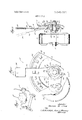
- FIG. 1 is a perspective view on a reduced scale of a rotary mower which is typical example of a wheeled device to which the invention is applicable.
- FIG. 2 is a side elevation of an adjustable wheel bracket assembly embodying the invention.
- FIG. 3 is a vertical cross section taken along the line 33 of F IG. 2.
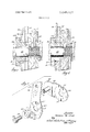
- FIG. 4 is an exploded perspective view of the wheel crank, spring lever, clamp bushing and clamp bolt.
- FIG. 5 is an enlarged cross section of the hub portion of the assembly prior to exerting clamping pressure on the shouldered bushing.
- FIG. 6 is a cross section similar to that shown in FIG. 5, but showing the parts after clamping pressure is exerted on the bushing.
- the adjustable wheel bracket assembly of the present invention is typically applied to each of the four wheels 10 of the rotary mower shown in FIG. 1.
- the assembly 12 comprises a backup plate 13 which is mounted fixedly to the skirt ll of the mower deck, as shown in FIG. 3.
- the deck skirt 11 typically has an opening 14 through which a tang 15 on the backup plate 13 projects, thus to key the backup plate 13 in secure proper position with respect to the skirt deck 11.
- the backup plate 13 is provided with a series of concentric bosses, namely, an inner boss 16, an intermediate boss 17, and an outer boss 18. These bosses face the swingable parts of the assembly, for purposes to be hereinafter described.
- crank 22 is made of stiff, heavy gauge steel, with an oblique intermediate portion 20.
- the inner end of crank 22 has a central opening 23 and peripheral locking lugs 24.
- the locking lugs 24 engage in corresponding locking apertures 25 near the inner end of a spring steel lever 26.
- Lever 26 is relatively flexible and has a handle 29 at its outer end. At its inner end lever 26 has an opening 27 of substantially the same size as the opening 23 in crank 22.
- crank lugs 24 in the lever apertures 25 couple the crank 22 and lever 26 so that these parts may be swung as a unit about the axis ofa mounting bolt 28 on which the parts are mounted to the backup plate 13 and deck skin 11, as shown in FIG. 3.
- a bushing 31 shouldered at 33 supports the assembled crank 22 and spring lever 26 on the mounting bolt 28.
- the end face 32 of bushing 31 seats against the boss 16 of backup plate 13 and bushing shoulder 33 seats against the inner end of the lever 26.
- the lever 26 is provided about its opening 27 with a conical offset or warp 35.
- Warp 35 is of sufficient depth of offset so that when the inner ends of the crank 22 and the lever 26 are placed into face contact prior to tightening the clamp bolt 28, as shown in FIG. 5, the spacing X between the crank 22 and the bottom of the warp 35 will be on the order of 0.0300.040 inch. In the FIG. 5 position of the parts, there will also be a spacing indicated at "Z in FIG. 5 between the end face 32 of the bushing 31 and the boss 16 of the backup plate 13.
- Clamping pressure is developed on the warp 35 by the mounting bolt 28 and bushing 31.
- Clamp bolt 28 has its head 36 engaged with the bushing 31 and has a nut 37 engaged with washers 40, 41 which intervene between the nut 37 and the inner surface of the deck skirt 1].
- the height of the wheel 10 is adjusted by springing flexible lever 27 to its broken-line position shown in FIG. 3 and swinging the lever and crank about the axis of mounting bolt 28. This action swings wheel axle 21 to a higher or lower position with respect to ground.
- Lever 26 is held in any selected position by one or another of the detents 42 which project from plate 13 and which selectively engage in the detent opening 43 in the lever 26.
- an adjustable wheel bracket assembly including a relatively stiff wheel axle crank, a relatively flexible adjusting lever keyed to the crank, a backup plate and detents with respect to which the lever is flexed in the course of adjusting lever position
- the improvement to bias the lever and crank together under tension and thus to take up tolerance and eliminate play in the assembly comprising a clamp for pressing the lever and crank together, said lever having a warp yieldable under clamp pressure to create tension in the lever and bias the assembly together without play between the assembled parts, said clamp comprising a bushing having an end face which engages the backup plate and a shoulder spaced from said face and in engagement with one of said crank and lever.
Landscapes
- Life Sciences & Earth Sciences (AREA)
- Environmental Sciences (AREA)
- Axle Suspensions And Sidecars For Cycles (AREA)
Abstract
Description
Claims (3)
Applications Claiming Priority (1)
| Application Number | Priority Date | Filing Date | Title |
|---|---|---|---|
| US4942170A | 1970-06-24 | 1970-06-24 |
Publications (1)
| Publication Number | Publication Date |
|---|---|
| US3649828A true US3649828A (en) | 1972-03-14 |
Family
ID=21959744
Family Applications (1)
| Application Number | Title | Priority Date | Filing Date |
|---|---|---|---|
| US49421A Expired - Lifetime US3649828A (en) | 1970-06-24 | 1970-06-24 | Adjustable wheel bracket assembly |
Country Status (2)
| Country | Link |
|---|---|
| US (1) | US3649828A (en) |
| CA (1) | CA919726A (en) |
Cited By (21)
| Publication number | Priority date | Publication date | Assignee | Title |
|---|---|---|---|---|
| US3928905A (en) * | 1974-07-01 | 1975-12-30 | Triax Co | Method of assembly for knock-down storage frame |
| US4321785A (en) * | 1980-12-08 | 1982-03-30 | Ataco Steel Products Co. | Wheel height adjuster |
| US4890951A (en) * | 1986-08-13 | 1990-01-02 | Nippon Seiko Kabushiki Kaisha | Webbing supporting device |
| US5249324A (en) * | 1992-07-31 | 1993-10-05 | A. J. Giammanco & Associates, Inc. | Adjustable wheel assembly for pool vacuums |
| US5253884A (en) * | 1991-12-13 | 1993-10-19 | Gary Landers | Roller adjustment means for in line skate |
| US5374072A (en) * | 1991-12-13 | 1994-12-20 | Landers; Gary | Roller adjustment system for in-line skates |
| US5586777A (en) * | 1995-06-05 | 1996-12-24 | Wolf; David | In line skate with dynamically adjustable wheels |
| WO1998009499A3 (en) * | 1996-09-05 | 1998-06-25 | Scott Thomason | Single lever height adjustment mechanism and method for a lawn mower |
| US5791004A (en) * | 1995-03-14 | 1998-08-11 | Colgate-Palmolive Company | Floor cleaning device |
| US6132128A (en) * | 1998-06-17 | 2000-10-17 | Prince Corporation | Snap-on control member |
| US6899345B1 (en) | 2003-03-26 | 2005-05-31 | John D. Bearden | Lawn mower adjustable wheel conversion assembly |
| US20070107404A1 (en) * | 2005-11-03 | 2007-05-17 | Agri-Fab, Inc. | Height adjustment system for a lawn maintenance device |
| US20100037578A1 (en) * | 2008-08-15 | 2010-02-18 | Jolliff Brian M | Height of cut adjustment mechanism for rotary cutting deck |
| US20110078990A1 (en) * | 2009-10-01 | 2011-04-07 | Tommy Joe Vachal | Wheel mounting/height adjustment mechanism and power equipment unit incorporating same |
| US20130118139A1 (en) * | 2011-11-15 | 2013-05-16 | Agri-Fab, Inc. | Sweeper height adjustment assembly |
| US8887480B2 (en) * | 2011-12-06 | 2014-11-18 | The Toro Company | Walk power mower with height of cut adjustment system having spring arm with replaceable locking pin |
| US20150037085A1 (en) * | 2013-07-31 | 2015-02-05 | Jeffrey D. Carnevali | Rotary coupling |
| US20180027731A1 (en) * | 2016-07-28 | 2018-02-01 | Mat Engine Technologies, Llc | Wheeled string trimmer mower |
| US20180103582A1 (en) * | 2016-07-28 | 2018-04-19 | Mat Engine Technologies, Llc | Wheeled string trimmer mower |
| US20200120875A1 (en) * | 2016-05-16 | 2020-04-23 | Cnh Industrial America Llc | Adjustable vanes for use in a cylindrical rotor cage of an agricultural harvester |
| US11097412B2 (en) * | 2019-04-16 | 2021-08-24 | Rekeft Dosky | Mechanic's creeper assembly |
Citations (1)
| Publication number | Priority date | Publication date | Assignee | Title |
|---|---|---|---|---|
| US2503884A (en) * | 1947-04-23 | 1950-04-11 | Charles S Noble | Blade weeding assembly |
-
1970
- 1970-06-24 US US49421A patent/US3649828A/en not_active Expired - Lifetime
-
1971
- 1971-02-10 CA CA105024A patent/CA919726A/en not_active Expired
Patent Citations (1)
| Publication number | Priority date | Publication date | Assignee | Title |
|---|---|---|---|---|
| US2503884A (en) * | 1947-04-23 | 1950-04-11 | Charles S Noble | Blade weeding assembly |
Cited By (24)
| Publication number | Priority date | Publication date | Assignee | Title |
|---|---|---|---|---|
| US3928905A (en) * | 1974-07-01 | 1975-12-30 | Triax Co | Method of assembly for knock-down storage frame |
| US4321785A (en) * | 1980-12-08 | 1982-03-30 | Ataco Steel Products Co. | Wheel height adjuster |
| US4890951A (en) * | 1986-08-13 | 1990-01-02 | Nippon Seiko Kabushiki Kaisha | Webbing supporting device |
| US5253884A (en) * | 1991-12-13 | 1993-10-19 | Gary Landers | Roller adjustment means for in line skate |
| US5374072A (en) * | 1991-12-13 | 1994-12-20 | Landers; Gary | Roller adjustment system for in-line skates |
| US5249324A (en) * | 1992-07-31 | 1993-10-05 | A. J. Giammanco & Associates, Inc. | Adjustable wheel assembly for pool vacuums |
| US5791004A (en) * | 1995-03-14 | 1998-08-11 | Colgate-Palmolive Company | Floor cleaning device |
| US5586777A (en) * | 1995-06-05 | 1996-12-24 | Wolf; David | In line skate with dynamically adjustable wheels |
| WO1998009499A3 (en) * | 1996-09-05 | 1998-06-25 | Scott Thomason | Single lever height adjustment mechanism and method for a lawn mower |
| US6132128A (en) * | 1998-06-17 | 2000-10-17 | Prince Corporation | Snap-on control member |
| US6899345B1 (en) | 2003-03-26 | 2005-05-31 | John D. Bearden | Lawn mower adjustable wheel conversion assembly |
| US20070107404A1 (en) * | 2005-11-03 | 2007-05-17 | Agri-Fab, Inc. | Height adjustment system for a lawn maintenance device |
| US20100037578A1 (en) * | 2008-08-15 | 2010-02-18 | Jolliff Brian M | Height of cut adjustment mechanism for rotary cutting deck |
| US7716907B2 (en) | 2008-08-15 | 2010-05-18 | Deere & Company | Height of cut adjustment mechanism for rotary cutting deck |
| US20110078990A1 (en) * | 2009-10-01 | 2011-04-07 | Tommy Joe Vachal | Wheel mounting/height adjustment mechanism and power equipment unit incorporating same |
| US7958943B2 (en) | 2009-10-01 | 2011-06-14 | Exmark Manufacturing Company, Incorporated | Wheel mounting/height adjustment mechanism for a power equipment unit |
| US20130118139A1 (en) * | 2011-11-15 | 2013-05-16 | Agri-Fab, Inc. | Sweeper height adjustment assembly |
| US8887480B2 (en) * | 2011-12-06 | 2014-11-18 | The Toro Company | Walk power mower with height of cut adjustment system having spring arm with replaceable locking pin |
| US20150037085A1 (en) * | 2013-07-31 | 2015-02-05 | Jeffrey D. Carnevali | Rotary coupling |
| US20200120875A1 (en) * | 2016-05-16 | 2020-04-23 | Cnh Industrial America Llc | Adjustable vanes for use in a cylindrical rotor cage of an agricultural harvester |
| US10959379B2 (en) * | 2016-05-16 | 2021-03-30 | Cnh Industrial America Llc | Adjustable vanes for use in a cylindrical rotor cage of an agricultural harvester |
| US20180027731A1 (en) * | 2016-07-28 | 2018-02-01 | Mat Engine Technologies, Llc | Wheeled string trimmer mower |
| US20180103582A1 (en) * | 2016-07-28 | 2018-04-19 | Mat Engine Technologies, Llc | Wheeled string trimmer mower |
| US11097412B2 (en) * | 2019-04-16 | 2021-08-24 | Rekeft Dosky | Mechanic's creeper assembly |
Also Published As
| Publication number | Publication date |
|---|---|
| CA919726A (en) | 1973-01-23 |
Similar Documents
| Publication | Publication Date | Title |
|---|---|---|
| US3649828A (en) | Adjustable wheel bracket assembly | |
| EP0080893B1 (en) | Security device | |
| US4735428A (en) | Vehicle quarter fender | |
| GB1294667A (en) | Improvements in or relating to sports vehicles | |
| US3388929A (en) | Implement mounting frame | |
| US2789832A (en) | Combined motorcycle tow bar coupling and front wheel lift | |
| US2579853A (en) | Wheel manipulating tool | |
| US2654112A (en) | Caster having a swivel lock | |
| US3995945A (en) | Axle adjacent mounted bicycle mirror assembly | |
| US4580935A (en) | Tie down system | |
| DE455094C (en) | Device for adjusting the camber of the front wheels of motor vehicles | |
| CA2052123A1 (en) | Pivotable steering wheel mechanism and biasing means | |
| US2830464A (en) | Flexible steering wheel | |
| US3799581A (en) | Wheel hub with improved adjustable eccentric mounting | |
| US1461497A (en) | Radius leaf | |
| US3664683A (en) | Basket attachment for tricycle | |
| CA1039335A (en) | Means for securing axle to frame | |
| JPS6276093U (en) | ||
| US4960286A (en) | Self-propelled vehicle | |
| US4303224A (en) | Camber and caster adjusting tool | |
| US3754616A (en) | Drive mechanism for mowers | |
| US2456536A (en) | Parking stand and mounting therefor | |
| FR2457207A1 (en) | Mud guard mounting on lorry - has U=bolt with clamping clip fitting under bar and over bracket | |
| US2570656A (en) | Boat towing assembly | |
| US4705282A (en) | Vehicle with readily mountable steering handle |
Legal Events
| Date | Code | Title | Description |
|---|---|---|---|
| AS | Assignment |
Owner name: GENERAL ELECTRIC CREDIT CORPORATION 8131 LBJ FREEW Free format text: SECURITY INTEREST;ASSIGNOR:GILSON BROTHERS COMPANY A CORP OF DE;REEL/FRAME:004335/0243 |
|
| AS | Assignment |
Owner name: GILSON BROTHERS COMPANY Free format text: RELEASED BY SECURED PARTY;ASSIGNOR:GENERAL ELECTRIC CREDIT CORPORATION, A NY CORP.;REEL/FRAME:004940/0620 Effective date: 19870903 Owner name: OUTBOARD MARINE CORPORATION, A CORP. OF DE,ILLINOI Free format text: ASSIGNMENT OF ASSIGNORS INTEREST;ASSIGNOR:LAWN-BOY, INC., A DE CORP.;REEL/FRAME:004940/0611 Effective date: 19870904 Owner name: LAWN-BOY, INC. Free format text: ASSIGNMENT OF ASSIGNORS INTEREST.;ASSIGNOR:GILSON BROTHERS COMPANY;REEL/FRAME:004940/0614 Effective date: 19870906 Owner name: OUTBOARD MARINE CORPORATION, 100 SEAHORSE DRIVE, W Free format text: ASSIGNMENT OF ASSIGNORS INTEREST.;ASSIGNOR:LAWN-BOY, INC., A DE CORP.;REEL/FRAME:004940/0611 Effective date: 19870904 |
|
| AS | Assignment |
Owner name: LAWN-BOY INC., A CORP OF DELAWARE, WISCONSIN Free format text: ASSIGNMENT OF ASSIGNORS INTEREST.;ASSIGNOR:OUTBOARD MARINE CORPORATION,;REEL/FRAME:005277/0255 Effective date: 19900619 |
|
| AS | Assignment |
Owner name: TORO COMPANY, THE, MINNESOTA Free format text: ASSIGNMENT OF ASSIGNORS INTEREST;ASSIGNOR:LAWN-BOY INC.;REEL/FRAME:007029/0339 Effective date: 19940318 |