US364936A - Abrasion of - Google Patents
Abrasion of Download PDFInfo
- Publication number
- US364936A US364936A US364936DA US364936A US 364936 A US364936 A US 364936A US 364936D A US364936D A US 364936DA US 364936 A US364936 A US 364936A
- Authority
- US
- United States
- Prior art keywords
- diaphragms
- casing
- pump
- fluid
- filter
- Prior art date
- Legal status (The legal status is an assumption and is not a legal conclusion. Google has not performed a legal analysis and makes no representation as to the accuracy of the status listed.)
- Expired - Lifetime
Links
- 238000005299 abrasion Methods 0.000 title description 3
- 239000012530 fluid Substances 0.000 description 8
- 239000000463 material Substances 0.000 description 8
- 238000001914 filtration Methods 0.000 description 5
- XLYOFNOQVPJJNP-UHFFFAOYSA-N water Substances O XLYOFNOQVPJJNP-UHFFFAOYSA-N 0.000 description 5
- 238000010276 construction Methods 0.000 description 4
- 239000012535 impurity Substances 0.000 description 4
- 239000004576 sand Substances 0.000 description 4
- 239000008187 granular material Substances 0.000 description 3
- 238000013019 agitation Methods 0.000 description 2
- 239000002969 artificial stone Substances 0.000 description 1
- 239000011248 coating agent Substances 0.000 description 1
- 238000000576 coating method Methods 0.000 description 1
- 239000000571 coke Substances 0.000 description 1
- 238000010586 diagram Methods 0.000 description 1
- 230000005484 gravity Effects 0.000 description 1
- 230000001939 inductive effect Effects 0.000 description 1
- 238000000034 method Methods 0.000 description 1
- 238000005325 percolation Methods 0.000 description 1
Images

Classifications
-
- B—PERFORMING OPERATIONS; TRANSPORTING
- B01—PHYSICAL OR CHEMICAL PROCESSES OR APPARATUS IN GENERAL
- B01D—SEPARATION
- B01D29/00—Filters with filtering elements stationary during filtration, e.g. pressure or suction filters, not covered by groups B01D24/00 - B01D27/00; Filtering elements therefor
- B01D29/39—Filters with filtering elements stationary during filtration, e.g. pressure or suction filters, not covered by groups B01D24/00 - B01D27/00; Filtering elements therefor with hollow discs side by side on, or around, one or more tubes, e.g. of the leaf type
Definitions
- This invention is intended to increase the efficieney or capacity of porous filtering-diaphragms; and it consists in the use of a suction-pump for inducing a vacuum within such diaphragms or filtering media, and in continuously passing over the surfaces of such diaphragms a volume of water in excess of that which can be filtered, to agitate, in contact with the diaphragms, granular abrading material to remove the impurities deposited thereon.
- a suction-pump for inducing a vacuum within such diaphragms or filtering media, and in continuously passing over the surfaces of such diaphragms a volume of water in excess of that which can be filtered, to agitate, in contact with the diaphragms, granular abrading material to remove the impurities deposited thereon.
- the diaphragms may be of tubular form, or rectangular or prismatic, and are shown herein as square prisms, constructed according to the specification in my patent application No. 224,210, filed January 13, 1887.
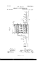
- Figure 1 is a diagram showing a filter havingits casing in section where hatched, and containing a series of tubular filtering-diaphragms connected with a suctioupump, and the bottom of the casing being also connected with a separate force-pump.
- Fig. 2 is a side view of one of the tubular filterdiaphragms, with one portion broken away to show its porous construction, and
- Fig. 3 is a transverse section 011 line .r x in Fig. 2.
- a is the filter-casing,which is shown open at the top, but may be closed, if desired.
- the filter-diaphragm shown herein is formed by Wrapping wire-gauze 8 around a perforated metallic tube, 8', and applying outside of the (No model.)
- a false bottom, 0, is placed within the filtercasing beneath the diaphragms to sustain a mass of granular abrading material in contact with the diaphragms, and perforations c are made through such false bottom to admit a current of fluid among the sand and diaphragms.
- Such fluid is supplied through a pipe,f, by a force-pump, g, and is furnished in a greater volume than the diaphragms are capable of filtering, to induce a violent agitation of the abradin g material against their surfaces.
- the surplus of fluid is discharged from the upper part of the filter by any convenient means, as the pipe h, the aperture of the pipe being guarded by a baffle-plate, i, and the sand being used of such size and gravity as to re main within the casing.
- My construction operates as follows: The fluid, being delivered within the casing by the pump 9, is drawn through the porous surfaces of the diaphragms Z) by the suction of the pump and the constant agitation of the sand or other granular material against the surfaces of the diaphragms serves to remove the impurities therefrom, while the flow of water from the pipe h continuously removes such impurities from the casing, and thus maintains the diaphragms in a clean and efficient condition.
- coke breeze or any suitable abradi ng material may be used, and the false bottom 0 may be replaced with fine gravel or any required form of strainer on the end of the inlet-pipe, to prevent the granular matcrial from clogging the same.
Landscapes
- Chemical & Material Sciences (AREA)
- Chemical Kinetics & Catalysis (AREA)
- Filtering Materials (AREA)
Description
(No Model.) 2 Sheets-8heet 1. J. W. HYATT.
ABRASION OF FILTER DIAPHRAGMS. No. 364,936. PatentedJune 14, 1887.
2 Sheets-Sheet 2 (No Model J. W. HYATT.
ABRASION 0F FILTER DIAPHRAGMS.
Patented June 1 4 qflfiesii- N PETiRs. Phom \Jlhographer, Washmglan, D. t:v
UNITED STATES ATENT FFICET JOHN \V. HYATT, OF NEVARK, NE\V JERSEY.
ABRASION OF FILTER-DIAPHRAGMS.
SPECIFICATION forming part of Letters Patent No. 364,936,dated June 14, 1887.
Application filed March 7, 1887.
To all whom it may concern:
Be it known that 1, JOHN W. HYATT, acitizen of the United States, residing at Newark, Essex county, New Jersey, have invented certain new and useful Improvements in Abrasion of Filteririg-Diaphragms, fully described and represented in the following specification and the accompanying drawings, forming a part of the same.
This invention'is intended to increase the efficieney or capacity of porous filtering-diaphragms; and it consists in the use of a suction-pump for inducing a vacuum within such diaphragms or filtering media, and in continuously passing over the surfaces of such diaphragms a volume of water in excess of that which can be filtered, to agitate, in contact with the diaphragms, granular abrading material to remove the impurities deposited thereon. By this construction a very rapid percolation of the fluid through the porous diaphragms is secured, and the surfaces are kept continuously cleansed, so as to operate with the utmost efficiency.
The diaphragms may be of tubular form, or rectangular or prismatic, and are shown herein as square prisms, constructed according to the specification in my patent application No. 224,210, filed January 13, 1887.
Figure 1 is a diagram showing a filter havingits casing in section where hatched, and containing a series of tubular filtering-diaphragms connected with a suctioupump, and the bottom of the casing being also connected with a separate force-pump. Fig. 2 is a side view of one of the tubular filterdiaphragms, with one portion broken away to show its porous construction, and Fig. 3 is a transverse section 011 line .r x in Fig. 2.
In the drawings, a is the filter-casing,which is shown open at the top, but may be closed, if desired.
1) are the filtering-diaphragms, presenting a porous filtering-surface upon all their external sides, and provided internally with a passage for the fluid to a header, 0. .Such header is connected by a pipe, (Z, with the suction-inlet of a pump, p.
The filter-diaphragm shown herein is formed by Wrapping wire-gauze 8 around a perforated metallic tube, 8', and applying outside of the (No model.)
wire-gauze a coating of artificial stone, 8 This construction of the diaphragm is not claimed herein, as it forms no partot' my pres ent invention.
A false bottom, 0, is placed within the filtercasing beneath the diaphragms to sustain a mass of granular abrading material in contact with the diaphragms, and perforations c are made through such false bottom to admit a current of fluid among the sand and diaphragms. Such fluid is supplied through a pipe,f, by a force-pump, g, and is furnished in a greater volume than the diaphragms are capable of filtering, to induce a violent agitation of the abradin g material against their surfaces. The surplus of fluid is discharged from the upper part of the filter by any convenient means, as the pipe h, the aperture of the pipe being guarded by a baffle-plate, i, and the sand being used of such size and gravity as to re main within the casing.
My construction operates as follows: The fluid, being delivered within the casing by the pump 9, is drawn through the porous surfaces of the diaphragms Z) by the suction of the pump and the constant agitation of the sand or other granular material against the surfaces of the diaphragms serves to remove the impurities therefrom, while the flow of water from the pipe h continuously removes such impurities from the casing, and thus maintains the diaphragms in a clean and efficient condition. v
I hereby disclaim my patent application No. 219,574, filed November 23, 1886, in which I have claimed, broadly, the use of abrading material agitated with the unfiltered fluid to cleanse the surface of a permanent porous filtering-diaphragm, whatever the shape of the latter may be.
In practicing my present invention coke breeze or any suitable abradi ng material may be used, and the false bottom 0 may be replaced with fine gravel or any required form of strainer on the end of the inlet-pipe, to prevent the granular matcrial from clogging the same.
It will be noticed that the sand or other abrading material introduced into the filtercasing is manifestly not designed to perform filtering functions, and that any filtration cffeeted by such abrading material is wholly immaterial to the process of the invention itself.
Having thus set forth my invention, what I claim herein is- The combination, with an open filter-casing, of porous diaphragms supported therein and having their outlet conneotcdwith a suctionpump, granular material in the casing in contact with such (liaphragms, a force-pump supplying a current of water to the casing through such granular material, and an overflow from the upper part of the casing, the whole being arranged and operated for the force-pump to supply the water for filtration and an excess of water for agitating the abrading material, such excess flowing continuously from the easing to remove the impurities, and the suctionpump operating to draw the fluid through the porous diaphragms, as and for the purpose set forth.
V In testimony whereof I have hereunto set my hand in the presence of two subscribing witnesses.
JOHN w. HYA'IT.
Witnesses: i
FRANK L. MORTON, Tnos. S. CRANE.
Publications (1)
| Publication Number | Publication Date |
|---|---|
| US364936A true US364936A (en) | 1887-06-14 |
Family
ID=2433963
Family Applications (1)
| Application Number | Title | Priority Date | Filing Date |
|---|---|---|---|
| US364936D Expired - Lifetime US364936A (en) | Abrasion of |
Country Status (1)
| Country | Link |
|---|---|
| US (1) | US364936A (en) |
Cited By (1)
| Publication number | Priority date | Publication date | Assignee | Title |
|---|---|---|---|---|
| US2562972A (en) * | 1944-11-14 | 1951-08-07 | Rca Corp | Method and apparatus for purifying and testing a fluid dielectric and filling a container or an electrical capacitor therewith |
-
0
- US US364936D patent/US364936A/en not_active Expired - Lifetime
Cited By (1)
| Publication number | Priority date | Publication date | Assignee | Title |
|---|---|---|---|---|
| US2562972A (en) * | 1944-11-14 | 1951-08-07 | Rca Corp | Method and apparatus for purifying and testing a fluid dielectric and filling a container or an electrical capacitor therewith |
Similar Documents
| Publication | Publication Date | Title |
|---|---|---|
| US590868A (en) | Filter | |
| US364936A (en) | Abrasion of | |
| US2995204A (en) | Fluid filter and strainer | |
| US593666A (en) | Signors to the o | |
| US206938A (en) | Improvement in water-filters | |
| US1246850A (en) | Automatic self-cleaning filter. | |
| US316925A (en) | Kael wilhelm vog-el | |
| US870727A (en) | Method of cleaning filters. | |
| US722632A (en) | Filter. | |
| US222731A (en) | Improvement in water-filters | |
| US345773A (en) | Water-supply system | |
| US317457A (en) | Minster | |
| US1189114A (en) | Apparatus for the filtration, aeration, and gasification of liquids. | |
| US203110A (en) | Improvement in water-purifiers | |
| US597248A (en) | Filter | |
| US364933A (en) | Appaeatus for cleansing | |
| US364935A (en) | hyatt | |
| US176593A (en) | Improvement in water-filters | |
| US235764A (en) | Thomas guineas | |
| US419023A (en) | Filter | |
| US355004A (en) | Filter | |
| US535295A (en) | Filter | |
| US372530A (en) | Filter | |
| US791213A (en) | Water-filter. | |
| US377388A (en) | Water filter and purifier |