US3641908A - Liquid spreader - Google Patents
Liquid spreader Download PDFInfo
- Publication number
- US3641908A US3641908A US837422A US3641908DA US3641908A US 3641908 A US3641908 A US 3641908A US 837422 A US837422 A US 837422A US 3641908D A US3641908D A US 3641908DA US 3641908 A US3641908 A US 3641908A
- Authority
- US
- United States
- Prior art keywords
- members
- liquid
- spreader
- load
- distributing
- Prior art date
- Legal status (The legal status is an assumption and is not a legal conclusion. Google has not performed a legal analysis and makes no representation as to the accuracy of the status listed.)
- Expired - Lifetime
Links
- 239000007788 liquid Substances 0.000 title claims abstract description 37
- 239000000463 material Substances 0.000 claims abstract description 34
- 238000004140 cleaning Methods 0.000 claims abstract description 18
- 238000012545 processing Methods 0.000 claims abstract description 13
- 238000012546 transfer Methods 0.000 claims description 56
- 238000006073 displacement reaction Methods 0.000 claims description 6
- 239000012530 fluid Substances 0.000 claims description 3
- 230000000694 effects Effects 0.000 claims description 2
- 238000007373 indentation Methods 0.000 description 4
- 230000002411 adverse Effects 0.000 description 2
- 238000003780 insertion Methods 0.000 description 2
- 230000037431 insertion Effects 0.000 description 2
- 125000006850 spacer group Chemical group 0.000 description 2
- 241001508691 Martes zibellina Species 0.000 description 1
- 238000010276 construction Methods 0.000 description 1
- 230000003247 decreasing effect Effects 0.000 description 1
- 238000011161 development Methods 0.000 description 1
- 210000005069 ears Anatomy 0.000 description 1
- 239000002184 metal Substances 0.000 description 1
- 238000012986 modification Methods 0.000 description 1
- 230000004048 modification Effects 0.000 description 1
- 230000002035 prolonged effect Effects 0.000 description 1
- 230000000717 retained effect Effects 0.000 description 1
- 238000007789 sealing Methods 0.000 description 1
- 238000000926 separation method Methods 0.000 description 1
Images


Classifications
-
- G—PHYSICS
- G03—PHOTOGRAPHY; CINEMATOGRAPHY; ANALOGOUS TECHNIQUES USING WAVES OTHER THAN OPTICAL WAVES; ELECTROGRAPHY; HOLOGRAPHY
- G03B—APPARATUS OR ARRANGEMENTS FOR TAKING PHOTOGRAPHS OR FOR PROJECTING OR VIEWING THEM; APPARATUS OR ARRANGEMENTS EMPLOYING ANALOGOUS TECHNIQUES USING WAVES OTHER THAN OPTICAL WAVES; ACCESSORIES THEREFOR
- G03B17/00—Details of cameras or camera bodies; Accessories therefor
- G03B17/48—Details of cameras or camera bodies; Accessories therefor adapted for combination with other photographic or optical apparatus
- G03B17/50—Details of cameras or camera bodies; Accessories therefor adapted for combination with other photographic or optical apparatus with both developing and finishing apparatus
- G03B17/52—Details of cameras or camera bodies; Accessories therefor adapted for combination with other photographic or optical apparatus with both developing and finishing apparatus of the Land type
Definitions
- the rod functions as a spring urging the movable spreader member towards the fixed spreader member Field of 95/89 13 when the spreader members are in a liquid-spreading position, and the rod acts as a support when the movable spreader member is pivoted towards an inoperative position in which ReterencesCited v UNITED STATES PATENTS 2,483,389 10/1949 3,245,335 4/1966 Sable n a p a d w a w w t m m C m n S g e.
- Apparatus for spreading a liquid in a uniform layer of predetermined thickness between two sheets of photographic sheet material generally includes two substantially parallel rigid members predeterminately spaced apart and so constructed and proportioned with respect to each'other as to provide a pressure-generating gap or slot through which the sheet material is drawn.
- the pressure-generating gap generates a hydraulic pressure in a liquid located between layers of sheet material to spread the liquid between and in contact with the interface surfaces of the layers as they are drawn between the rigid members. As the layers are drawn between the rigid members some of the liquid escapes from between the layers and is deposited on the rigid members.
- the spreading apparatus should be constructed to provide for ease of removal of the spreader .from a camera; separation of the various parts of the spreader to provide for ease of cleaning; and means on the spreader cooperating with the camera structure to facilitate insertion and proper orientation of the spreader in the camera.
- the invention has, as one object, the provision of a simple and inexpensive device including a substantially fixed gap for distributing a liquid in a uniform layer of predetermined thickness between two layers of sheet material moved through said gap, said device including means for pivotally connecting a stationary spreader member and a movably mounted spreader member for movement from a liquid-spreading position to an inoperative position wherein said members-are sufficiently spaced apart to allow for cleaning of said members.
- Another object of the invention is to provide in a device as set forth above connecting means in the form of a rod which functions as a spring when the device is in a liquid-distributing position and either as a hinge or pivot when one of the spreader members is moved towards and from the inoperative position.
- Another object of the invention is to provide in a device as set forth above means for receiving and redistributing forces from said rod to one of said members.
- Still another object of the invention is to provide in a liquidspreading apparatus of the type set forth above including two members pivotally coupled to each other for movement between a first position in which the members define a pressure-generating gap and a second position wherein portions of said members are spaced apart, means engageable by structure within a camera for insuring that the members are in the first position and that the spreading apparatus is properly orientated within the camera when the camera's loading door is closed.
- FIG. 1 is a perspective view, partly in section, showing photographic apparatus in the form of a camera having one form of spreader means therein, said camera being shown in the opener loading position;
- FIG. 2 is a fragmentary sectional view taken substantially along the line 2-2 of FIG. 1;
- FIG. 3 is a rear perspective view of another form of spreader means
- FIG. 4 is a front perspective view of the spreader means of FIG. 3;
- FIG. 5 is an exploded perspective view of the spreader means of FIG. 3;
- FIG. 6 is a front perspective view of the spreader means of FIG. 3 shown in the inoperative position
- FIG. 7 is a rear perspective view, partly in section, of another form of spreader means
- FIG. 8 is a rear exploded perspective view of another form of spreader means
- FIG. 9 is a sectional view of the spreader means of FIG. 8.
- FIG. 10 is a rear exploded perspective view of another form of spreader means similar to that of FIG. 8;
- FIG. 11 is a front perspective view of still another form of spreader means
- FIG. 12 is a front perspective view, partly in section, of still another form of spreader, the members ofthe spreader being shown in a nonspreading condition; 7
- FIG. 13 is a front exploded perspective view, partly in section, of the spreader shown in FIG. 12;
- FIG. 14 is a sectional elevational view taken along the line 14-14 of FIG. 12 with the spreader means being shown in a liquid-distributing position;
- FIG. 15 is a perspective view, partly in section, of the spreader of FIG. 13 shown mounted in a camera.
- FIG. 1 a camera of the self-developing type, indicated generally by reference numeral 10, and including camera body 12, bellows l4, lens and shutter housing 16 and the usual braces and supports for maintaining the various elements in operational relation to one another.
- Camera body 12 is closed at its rear by camera back 18 to form an exposure chamber which contains a film unit indicated generally at 20 in FIG. 2.
- Film unit 20, not shown in FIG. 1 in order to more clearly show the details of spreader means 22, may be of the type disclosed, for example, in U.S. Pat. Nos. 3,161,122; 3,161,516; and 3,165,039.
- Camera back 18 which is of a generally rectangular configuration includes an upstanding portion 24 extending around the periphery of camera back 18.
- Upstanding portion 24 is provided at one end with suitable means (not shown) for pivotally connecting camera back 18 to the remainder of the camera.
- Portion 24 is provided at its opposite end with a slot or aperture 26 having light-sealing means 28 resiliently associated therewith to prevent the leakage of light into the camera.
- Camera body 12 is provided with recessed portions 30 and 32 which cooperate with the top surface 34 of portion 24 to define a slot 36 through which leader 38 of film unit 20 may be withdrawn to properly position end 40 of-film unit 20 between the spreader members of spreader means 22.
- Suitable means e.g., a resilient flap member 42 extending across the entire width of slot 36, may be provided for preventing the leakage of light through slot 36 into the camera.
- Spreader means 22 is provided for properly rupturing a container 44 of processing liquid and evenly distributing the liquid in a layer between sheets 46 and 48 of film unit 20.
- Spreader means 22 is comprised of a pivotally mounted spreader member 50, a stationary spreader member 52 and an elongated resilient member in the form of a rod 54 which connects one of the spreader members 52 with the other spreader member 50 for movement between a liquid-distributing position and an inoperative position as will be more clearly described hereinafter.
- Spreader members 50 and 52 include portions 56 and 58 which cooperate to define a pressure-generating gap 60 therebetween, said gap 60 being in alignment with slot 26 when the spreader means is properly positioned within the camera. As can be seen in FIG.
- portions 46 and 58 include end portions 62 and 64, respectively, which converge ahead of gap 60 and terminate in facing, substantially parallel surfaces for engaging margins of sheets 46 and 48 ahead of said gap 60 for preventing escape of the processing liquid from between the sheets.
- Spreader member 50 also includes a base portion 66 which extends from portion 56 to an edge portion 68which is at a right angle to base portion Extending from edge portion 68 and at a 90 angle thereto is a pair of tab members 70 which are integral extensions of edge portion 68. Tab members 70 partially encompass rod 54 and help to maintain spreader member 50 operatively coupled to spreader member 52 when the other spreader member 50 is moved to and from a liquid-distributing posi- .tion.
- Base portion 66 has a load-transfer section 72 punched out of the sheet material of member 50 and at a right angle to portion v66 for transferring a load from rod 54 to spreader member 50 for resiliently urging member 50 towards spreader member 52 when spreader members 50 and 52 are in a liquiddistributing position, as shown in FIG. 2.
- Spreader member 52 further includes a base portion 74 having a pair of leg portions 76 and 78 bent at right angles thereto, said leg portions 76 and 78 having aperture'means 80 therein for receiving'the ends ,of rod 54, and means (not shown) for limiting the minimum width of pressure-generating gap 60.
- Upstanding portion 24 of camera back 18 is provided with suitable'means, e.g., ribs 82 positioned at opposite ends of members 50 and 52 and spring means 84, for frictionally maintaining spreader means 22 in alignment with slot 26.
- leader 38 is pulled to the right to properly position end'40 such that it protrudes through gap 60 and slot 26. Subsequent pulling on leader 38 will result in the breaking of the heat seal between it and the film unit. End 40 is then pulled to the right (as viewed in FIG. 2) drawing pod 44 containing the processing liquid into the pressure-generating gap 60 until the pressure of the liquid in pod 44 exceeds a predetermined limitat which the pod bursts and the fluid is evenly distributed between the sheets 46, 48.
- the thickness of the layer of liquid spread is in part controlled by the width of the pressure-generating gap, i.e., the distance between members 50, 52. As stated hereinbefore, the minimum width of this gap 60 is preset.
- the width of the gap 60 can be inadvertently increased by allowing the processing liquid, which may be highly alkaline, to remain on superposed parts of the spreader means 22.
- This processing liquid when subjected to the atmosphere for a prolonged period of time will dry leaving a deposit which over a period of time can build up to such proportions as to increase the minimum width of gap 60 thereby adversely affecting the quality of the processed unit.
- the spreader means of the instant invention may be readily removed from the camera, the spreader means 22 being retained in the camera by spring means 84, so that the various parts thereof may be cleaned.
- the spreading means is removed from the camera and spreader member 50 is rotated about rod 54 from a liquiddistributing position wherein surface 56 cooperates with surface 58 to define gap 60 to an inoperative position wherein members 50, 52 are sufficiently spaced apart to allow for cleaning of said members.
- This operation could be performed without removing the spreader means from the camera back 18; however, removing the spreader means from the camera back will facilitate the cleaning thereof.
- the spreader means may be inserted into the camera upside down, i.e., with member 52 positioned above member 50, and gap 60 will still be in alignment with slot 26.
- load-transfer section 72 is slightly above a horizontal plane containing apertures 80.
- rod 54 which has an intermediate portion in contact with section 72, assumes a slightly curved and stressed condition when members 50, 52 are in the liquid-distributing position and a substantially linear and unstressed condition when said members 50, 52 are in the inoperative position, e.g., see FIGS. 3 and 6, respectively.
- section 72 is located at a point higher than a horizontal plane containing apertures 80 but is located under an intermediate portion of rod 54.
- This bows rod 54 such that it acts as a spring to resiliently urge spreader member 50 towards spreader member '52.
- member 50 is rotated towards the inoperative positionsection 72 rotates about rod 54 to a position where it no longer bows rod 54.
- rod 54 functions as a hinge rather than a spring to maintain spreader members 50 and 52 operatively coupled to each other.
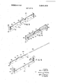
- FIG. 3 shows a rear perspective view of a spreader means 122 comprised of a pivotally mounted spreader member 150, a stationary spreader member 152 and a resilient member in the form of a rod 154 which connects members and 152 in the same manner as described with reference to spreader means 22.
- Spreader members 150, 152 include portions 156 and 158, respectively, which cooperate to define a pressure-generating gap 160 therebetween.
- Portions'l56 and 158 include end portions 162, 164 respectively, which converge ahead of gap 60 for engaging margins of sheets 46, 48 ahead of gap 160 for preventing escape of the processing liquid from between the sheets.
- Spreader member 150 also includes a base portion 166 having a section 170 curved through an arc of to enable it to partially encompass rod 154 and a plurality of load-transfer sections 172 which are pressed out of base portion 166 for transferring a load from rod 154 to spreader member 150' for resiliently urging member 150 towards member 152 when said members are in a liquid-distributing position.
- Spreading member 152 further includes a base portion 174 having a pair of leg portions 176, 178 extending therefrom and having aperture means 180 therein for receiving the ends of rod 154, and means 182 (see FIG. 5) comprising punchedout portions of legs 176, 178 for limiting the minimum width of gap 160. End portions 184 of spreader member 150 rest on the punched-out portions 182 when the spreader members 150, 152 are in the liquid-distributing position shown in FIGS. 3 and 4.
- the means (not shown) in FIGS. 1 and 2 for establishing a minimum width for gap 60 is the same as that shown in FIGS. 3-5.
- the spreader embodiment shown in FIGS. 3-6 differs from that shown in FIGS. 1 and 2 in that the former has a plurality of load-transfer elements 172 and only one tab section 170.
- FIG. 7 is shown another form of spreader means indicated generally at 222 comprised of a rotatably -mounted spreader member 250, a stationary spreader member 252 and a resilient rod 254 suitably mounted in apertures 280 located in leg portions 276, 278 of member 252.
- Rod 254 performs the same functions as the rods described hereinbefore.
- Spreader means 222 is similar to the spreader means 122 in all respects except that (l) load-transfer sections 272 are punched out of an intermediate portion of base portion 266 leaving a portion 290 which provides for greater rigidity in spreader member 250 as against spreader member 150 and (2) a plurality of curved sections 270 are provided as against a single section 170 in FIGS. 3-6.
- rod 254 and load-transfer sections 272 are such that the rod assumes a curved configuration when the spreader members are in a liquid-distributing position thereby resiliently urging member 250 towards member 252; and, functions as a hinge when member 250 is being moved to or from the inoperative position as described hereinbefore.
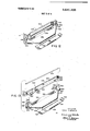
- the spreader means generally indicated at 300 comprises four units, i.e., a stationary spreader member 302 (identical to the stationary members disclosed in FIGS. l-7), a pivotally mounted spreader member 304, a resilient elongated rod 306 and a load-transfer element 308.
- Spreader member 304 includes a pair of tab means or hanger elements 310 which partially encircle rod 306 when the various parts are operatively connected.
- Load-transfer element 308 includes a punched-out" portion 312 (similar to portion 272 in FIG. 7) which functions as a load-receiving portion, and a plurality of load-distributing portions 314.
- Load-transfer element 308 may be centrally located on pivotally mounted spreader member 304 by any suitable means, e.g., by providing element 308 with one or more tabs 318 which line up with one or more indentations or recessed portions 320 in spreader member 304, said recessed portions 320 constraining element 308 against lateral movement, i.e., towards legs 316. It should be noted that the depth of indentations 320 is such that members 314 contact surface 322 before tabs 318 contact the bottom of indentations 320. This insures that the forces transmitted by member 308zwill be via members 314 only. Alternatively, the width or longitudinal dimension of member 308 could bemade substantially equal to that of spreader member 304 such that member 308 would be maintained in the correct position by legs 324 of spreader member 302.
- FIG. shows another form of spreader means similar to that shown in FIGS. 8 and 9, the major-change being that the tabs-318 and indentations 320 of the embodiment shown in FIGS. 8 and9 have been replaced by a pin-and-slot arrangement.
- Spreader member 304 is provided with an elongated slot326 for receiving end 328 of pin 330.
- pin 330 On the opposite side ofmember 308 pin 330 is provided with a load-receiving portion 332 of increased diameter.
- end 328 of pin 330 .does not contact the. bottom of slot 326. Accordingly, forces from a resilient rod 306 are received by loadweceiving portion 332 andare transmitted to spreader member 304 only by portions 314.
- the advantage in redistributing the forces towards the lateral ends of the movable spreader member is to lessen or obviate the chances that the movable spreader member will bow,.in the middle thereby decreasing the minimum height of the pressure-generating gap near its center.
- FIG. 11 shows still another embodiment of a spreader means.
- the spreader means is comprised of a stationary spreader member 402 which is. generally of the same configuration as the stationary spreader members disclosed in FIGS. 1-10, a pivotally mounted spreader member 404 and a resilient rod 406.
- Spreader member 404 includes a portion 408 which is rolled backupon itself to form a passageway for rod 406.
- the ends of rod 406 are mounted in apertures 412.
- the longitudinal axis of the passageway is located at a point higher than a horizontal plane containing apertures 412 thereby causing rod 406 to assume a bowed and stressed condition when the spreader members are in the liquid-distributingpositionas shown in FIG. 11.
- the diameter of rod 406 is less than that of the passageway to allow that portion of rod 406 within the passageway to assume a curved position. Forces from rod 406 are applied to spreader member 404 via the end portions 414 of the passageway.
- Spreader means 500 includes a first spreader member 502, a second spreader member 504 coupled with said first spreader member 502 for pivotal movement relative thereto, and a resilient connecting element in the form of a rod 506 for providing the pivotal connection between the spreader'members.
- Spreader member'502 includes a vertical member 508 and aplatform 510 formed at a right angle to each other and connected together by integral portion 512, portion 512 defining one side of a pressure-generating gap 514.
- a portion 516 of platform 510 located slightly ahead of gap 514 is relieved or punched out" of the platform to allow a portion of the pod of processing liquid located on the'film unit to extend before and during rupture thereof to facilitate movement of the film unit through pressure-generating gap S14.
- Platform 510 is terminated by a support member 518 which is connected to platform 510 by a downwardly turned portion 520.
- Support member 518 which cooperates with the lower portion 522 of vertical member 508 to properly position the spreader means 500 within a camera includes resilient upturned flanges 524, 526 and 528. As can be seen in FIG.
- upturned portion 528 engages a resilient member 532 located on the interior wall of camera door 534 of camera 530 to properly and securely position the spreader means in alignment with a withdrawal opening 536 in the camera and a withdrawal opening 538 in a film container 540 and yet be readily removable for cleaning. Should the operator or user of the camera fail to properly engage portion 528 with member 532 the spreader means will still be properly orientated within the camera 530 when the camera door 534 is closed. Closing of door 534 will being flanges 524 and 526 into contact with portions 542 and 544, respectively, of film container 540 supported by camera body 546 to move flange 528 into proper locking engagement with member 532.
- Spreader member 502 also includes a pair of up turned flanges 548 and 550 having apertures 552 therein for receiving the ends of rod 506. Extending from flanges 548 and 550 are tabs 554 and 556, respectively, for engaging walls of the camera to properly center the spreader means 500 within the camera and tabs 558 and 560, respectively, for limiting the clockwise (as viewed in FIG. 13) rotation of spreader member 504.
- Spreader member 504 includes a vertical member 562 and an upwardly inclined member 564 terminating in a slightly, upwardly inclined member 566, members 562 and 564 definingan angle of approximately 45 with each other and being connected by a portion 568.
- Portion 568 cooperates with portion 512 of spreader member 502 to define the minimum width of pressure-generating gap 514.
- Spacer members 570 located near the ends of portion 512 are provided for limiting the minimum distance, as measured in a vertical direction, between portions 512 and 568, i.e., spacers 570 provide for a pregap between portions 512 and 568.
- Vertical member 562 has its ends bent to form a pair of ears 572.
- Each car 572 is provided with an elongated slot 574 for receiving the ends of rod 506, the slots 574 being provided to allow spreader members 502 and 504 to move away from each other as the film unit passes through pressure-generating gap 514.
- a load-transfer means 576 e.g., a pin secured to vertical member 562 for transferring a load from rod 506 to spreader member 504.
- the top portion of load-transfer means 576 upon which an intermediate portion of rod 506 rests in the assembled condition, is located at a position higher, as viewed in FIG. 13, than a horizontal plane containing the tops of the elongated slots 574. Accordingly, when spreader means 500 is assembled as shown in FIGS.
- the rod 506 is slightly bowed in order to resiliently bias spreader member 504 toward spreader member 502.
- the ends of rod 506 function as pivot points to allow the members 502 and 504 to move from the liquiddistributing position shown in FIG. 14 to the position shown in FIG. 12 wherein they may readily be cleaned.
- Vertical member 562 terminates in an upwardly and inwardly sloped surface 578, as viewed in FIG. 13.
- inclined member 566 functions as a closure means for insuring that the spreader members are in the liquiddistributing position shown in FIG. 14 when the camera door is closed.
- the spreader means 500 is shown in a camera with spreader member 504 depicted as being in a partially open position, i.e., member 504 has been rotated counterclockwise by about 10 from the position shown in FIG. 14.
- each of the spreader members 502 and 504 include end portions 582 and 584, respectively, which converge-toward each other ahead of the pressure-generating gap 514 for engaging margins of a film unit to prevent escape of the processing liquid from between sheets of the film unit.
- the spreader means disclosed herein incorporates a minimum number of parts which may be readily and inexpensively manufactured from sheet metal stock.
- the spreader means can be easily removed from the camera, cleaned and reinserted in the camera.
- the spreader means Upon insertion into the camera the spreader means cooperates with the camera and/or film container to 'insure that the spreader means is located in exactly the correct position with respect to the camera and/or container and that the spreader members are in the liquid-distributing position.
- a photographic device for distributing a liquid between two layers of photographic sheet material comprising, in combination:
- a resilient connecting element mounted on one of said members, the other of said members being mounted on said resilient element for selective pivotal movement relative to said one member between said liquid-distributing position in which said load-transfer means receives a force from said connecting element for resiliently urging said members towards each other and an inoperative position wherein said load-transfer means does not receive a force from said connecting element urging said members towards each other and in which portions of said members are sufficiently spaced apart to allow for cleaning of said members.
- each of said surfaces include end portions converging ahead of said gap towards the end portions of the other surface for engaging margins of said sheets ahead of said gap to prevent escape of said liquid from between said sheets at said ends.
- each said member includes a' longitudinal portion extending from end to end thereof, said portions defining opposite sides of said device, said pressure-generating gap being spaced equidistantly from said opposite sides.
- each said flange includes means defining an elongated slot for receiving said resilient connecting element to enable said other member to move away from said one member as a photographic sheet material passes therebetween.
- the device as defined in claim 1 further including means engageable by a film container located within a camera for properly positioning said device within said camera.
- the device as defined in claim 1 further including closure means engageable'by structure within a camera for insuring that said members are in said liquid-distributing position when a loading door of the camera is closed.
- the device as defined in claim 7 further including means for releasably securing said device within a camera.
- a photographic device for distributing a liquid between two layers of photographic sheet material comprising, in combination:
- a resilient connecting element mounted on one of said members, the other of said members being mounted on said resilient element for pivotal movement relative to said one member between said liquid-distributing position in which said load-transfer means receives a force from said connecting element for resiliently urging said members towards each other and an inoperative position in which portions of said members are sutficiently spaced apart to allow for cleaning of said members, said members being formed of sheet material said other member including, as an integral part thereof, tab means, said tab means and said load-transfer means being engaged with said connecting element for maintaining said other member in operative relation with said connecting element during movement of said other member to and from said inoperative position.
- a photographic device for distributing a liquid between two layers of photographic sheet material comprising, in combination:
- liquid-distributing members formed of sheet material mounted in juxtaposed relation, said members including surfaces having portions defining a pressuregenerating gap therebetween when said members are in a liquid-distributing position;
- load-transfer means comprising an integral portion of one of said members and including a plurality of load-transfer sections
- a resilient connecting element comprising a rod mounted on the other of said members, with an intermediate portion thereof engaged with said load-transfer sections, said one member being mounted on said resilient connecting element adjacent respective ends thereof for pivotal movement relative to said other member between said liquiddistributing position in which said load-transfer means receives a force from said connecting element for resiliently urging said members towards each other and an inoperative position in which portions of said members are sufficiently spaced apart to allow for cleaning of said members.
- a photographic device for distributing a liquid between two layers of photographic sheet material comprising, in combination:
- said loadtransfer means comprising a separate load-transfer element including a load-receiving portion engaged with a medial section of said connecting element and load-distributing portions engaged with spaced sections of said other member for distributing the load from said connecting element to said other member to bias said other member towards said one member when said members are in the liquid-distributing position.
- said loadtransfer element includes means movably engaged with said other member for locating said load-transfer element intermediate the ends of said'other member, said means being constrained against movement relative to said other member in a direction lengthwise of said other member when said loadtransfer element is properly located relative to said other member.
- a photographic device for distributing a liquid between two layers of photographic sheet material comprising, in combination:
- a resilient connecting element mounted on one of said members, the'other of said members being mounted on said resilient element for pivotal movement relative to said one member between said liquid-distributing position in which said load-transfer means receives a force from said connecting element for resiliently urging said members towards each other and an inoperative position in which portions of said members are sufficiently spaced apart to allow for cleaning of said members, said connecting element comprising a rod mounted at its ends on said one member and said other member including said loadtransfer means, said load-transfer means being in engagement with an intermediate portion of said rod.
- a photographic device for distributing a liquid between two layers of photographic sheet material comprising, in combination:
- a resilient connecting element mounted on one of said members, the other of said members being mounted on said resilient element for pivotal movement relative to said one member between said liquid-distributing position in which said load-transfer means receives a force from said connecting element for resiliently urging said members towards each other and an inoperative position in which portions of said members are sufficiently spaced apart to allow for cleaning of said members, said other member including as integral parts thereof one of said surfaces and a base portion, said base portion including said load-transfer means.
- said one member includes as integral parts thereof one of said surfaces and a base portion having depending leg portions, said leg portions including aperture means for receiving said connecting element and means for limiting the minimum width of said pressure-generating gap.
- each said surface and its associated base portion have a V-shaped configuration in cross section.
- a photographic device for distributing a liquid between two layers of sheet material comprising:
- a first nonrolling spreader member defining an elongated sheet-contacting portion
- a second nonrolling spreader member defining an elongated sheet-contacting portion
- said means for mounting said first spreader member for pivotal displacement with respect to said second spreader member between a first position wherein said sheet-contacting portions are disposed-in juxtaposition to effect the spreading of a processing fluid between a pair of sheet materials when such sheet materials are disposed between said juxtaposed facing surfaces and relative motion is effected between such sheet materials and said spreader members and a second position wherein said sheet-contacting portions are disposed out of juxtaposition, said means defining an axis for said pivotal displacement passing through at least one of said spreader members and extending substantially parallel to said sheet-contacting portions when they are disposed in juxtaposition; and including means for mounting said spreader members for displacement at least away from each other when their said sheet-contacting portions are disposed in juxtaposition and including means for resiliently urging their said sheet-contacting portions toward each other at such times, said resiliently urging means being automatically rendered ineffective for purposes of urging said spreader members toward each other when said first spreader member is pivotally displaced from its first position with respect to said second spreader member into its said second position with respect there
- said mounting means comprises a member to which at least one of said spreader members is rotatably mounted.
- said mounting means comprises an elongated member extending lengthwise of said elongated sheet-contacting portions.
- first spreader member includes at least one aperture
- second spreader member comprises at least one aperture aligned with said firstmentioned aperture
- said mounting means comprises a member positioned through said aligned apertures.
- one of said apertures is only slightly larger in cross-sectional configuration than the cross-sectional configuration of said mounting means member and the other of said apertures is elongated with respect to said one aperture.
- the invention of claim 19 additionally including means establishing a minimum spacing between said sheet-contacting portions when they are in juxtaposition and means for precluding pivotal movement of said first spreader member in one direction about said axis with respect to said second spreader member when said sheet-contacting portions are in juxtaposition.
Landscapes
- Physics & Mathematics (AREA)
- General Physics & Mathematics (AREA)
- Agricultural Chemicals And Associated Chemicals (AREA)
- Photographic Developing Apparatuses (AREA)
- Camera Bodies And Camera Details Or Accessories (AREA)
Abstract
Apparatus for distributing a processing liquid between two sheets of material including a stationary spreader member and a movably mounted spreader member pivotally connected to each other by a rod to form a pressure-generating gap therebetween. The rod functions as a spring urging the movable spreader member towards the fixed spreader member when the spreader members are in a liquid-spreading position, and the rod acts as a support when the movable spreader member is pivoted towards an inoperative position in which portions of the spreader members are sufficiently spaced apart to allow for cleaning of the members.
Description
[ Feb. 15, 1972 United States Patent Eloranta [54] LIQUID SPREADER [72] inventor: Yarto K. Eloranta, Needham, Mass. Primary Examiner samuel S Matthews [73] Assignee: Polaroid Corporation, Cambridge, Mass. Assistant Examiner-Robert P. Greiner Attorney-Brown and Mikulka, Robert E. Corb and Alfred E. Corrigan 221 Filed: June 30,1969 21 Appl.No.: 837,422
- ABSTRACT Related US. Application Data u Apparatus for distributing a processing llquid between two [63] commuauon'm'pm of 672,036 Oct sheets of material includingastationary spreader member and a movably mounted spreader member pivotally connected to each other by a rod to form a pressure-generating gap 1967, abandoned.
[52] Cl. ......95/89R, 95/13 therebetween. The rod functions as a spring urging the movable spreader member towards the fixed spreader member Field of 95/89 13 when the spreader members are in a liquid-spreading position, and the rod acts as a support when the movable spreader member is pivoted towards an inoperative position in which ReterencesCited v UNITED STATES PATENTS 2,483,389 10/1949 3,245,335 4/1966 Sable n a p a d w a w w t m m C m n S g e. mm m m m mm D mm w 6 mm m r o d a C n ral- 7 Wm 2 h C m m S .mm mm Pm mm %H 5 PAIENIEnrw 15 m2 SHEET 1 OF 6 FIG. 2
INVENTOR VA/TO K. ELORANTA PATENTEDFEB 1 m2 SHEET 2 BF 6 ATTORNEYS PAIENTEH FEB 15 B72 sum 3. or 6 INVENTOR. m H. 6M
v E I and )wwoz and M wall 6am ATTORNEYS PAIENTEDFEB 1s m 3.641.908
SHEET 5 OF 6 INVENTOR. m H. M
524 EM m 2 Ar b uzv PATENTEUFEB 15 I972 3.641308 sum 6 [IF 6 INVENTOR.
LIQUID SPREADER This is a continuation-in-part of copending application Ser. No. 672,036 filed on Oct. 2, 1967 and now abandoned.
Apparatus for spreading a liquid in a uniform layer of predetermined thickness between two sheets of photographic sheet material generally includes two substantially parallel rigid members predeterminately spaced apart and so constructed and proportioned with respect to each'other as to provide a pressure-generating gap or slot through which the sheet material is drawn. The pressure-generating gap generates a hydraulic pressure in a liquid located between layers of sheet material to spread the liquid between and in contact with the interface surfaces of the layers as they are drawn between the rigid members. As the layers are drawn between the rigid members some of the liquid escapes from between the layers and is deposited on the rigid members. Should these deposits be allowed to remain on the rigid members they would buildup until they increased the minimum thickness of the pressure-generating gap which in turn may adversely affect the development of the photographic sheet material or, these deposits could cause uneven spreading of the processing liquid. In order to remove these deposits with a minimum of time and effort, the spreading apparatus should be constructed to provide for ease of removal of the spreader .from a camera; separation of the various parts of the spreader to provide for ease of cleaning; and means on the spreader cooperating with the camera structure to facilitate insertion and proper orientation of the spreader in the camera.
Accordingly, the invention has, as one object, the provision of a simple and inexpensive device including a substantially fixed gap for distributing a liquid in a uniform layer of predetermined thickness between two layers of sheet material moved through said gap, said device including means for pivotally connecting a stationary spreader member and a movably mounted spreader member for movement from a liquid-spreading position to an inoperative position wherein said members-are sufficiently spaced apart to allow for cleaning of said members.
Another object of the invention is to provide in a device as set forth above connecting means in the form of a rod which functions as a spring when the device is in a liquid-distributing position and either as a hinge or pivot when one of the spreader members is moved towards and from the inoperative position.
Another object of the invention is to provide in a device as set forth above means for receiving and redistributing forces from said rod to one of said members.
Still another object of the invention is to provide in a liquidspreading apparatus of the type set forth above including two members pivotally coupled to each other for movement between a first position in which the members define a pressure-generating gap and a second position wherein portions of said members are spaced apart, means engageable by structure within a camera for insuring that the members are in the first position and that the spreading apparatus is properly orientated within the camera when the camera's loading door is closed.
Other objects of the invention will in part be will in part appear hereinafter.
The invention accordingly comprises the apparatus possessing the construction, combination of elements and arrangement of parts which are exemplified in the following detailed disclosure, and the scope of the application of which will be indicated in the claims. I
For a fuller understanding of the nature and objects of the invention, reference should be had to the following detailed description taken in connection with the accompanying drawings wherein: 1
FIG. 1 is a perspective view, partly in section, showing photographic apparatus in the form of a camera having one form of spreader means therein, said camera being shown in the opener loading position;
FIG. 2 is a fragmentary sectional view taken substantially along the line 2-2 of FIG. 1;
obvious and FIG. 3 is a rear perspective view of another form of spreader means;
FIG. 4 is a front perspective view of the spreader means of FIG. 3;
FIG. 5 is an exploded perspective view of the spreader means of FIG. 3;
FIG. 6 is a front perspective view of the spreader means of FIG. 3 shown in the inoperative position;
FIG. 7 is a rear perspective view, partly in section, of another form of spreader means;
FIG. 8 is a rear exploded perspective view of another form of spreader means;
FIG. 9 is a sectional view of the spreader means of FIG. 8;
FIG. 10 is a rear exploded perspective view of another form of spreader means similar to that of FIG. 8;
FIG. 11 is a front perspective view of still another form of spreader means;
FIG. 12 is a front perspective view, partly in section, of still another form of spreader, the members ofthe spreader being shown in a nonspreading condition; 7
FIG. 13 is a front exploded perspective view, partly in section, of the spreader shown in FIG. 12;
FIG. 14 is a sectional elevational view taken along the line 14-14 of FIG. 12 with the spreader means being shown in a liquid-distributing position; and
FIG. 15 is a perspective view, partly in section, of the spreader of FIG. 13 shown mounted in a camera.
Referring now to the drawings, in FIG. 1 is shown a camera of the self-developing type, indicated generally by reference numeral 10, and including camera body 12, bellows l4, lens and shutter housing 16 and the usual braces and supports for maintaining the various elements in operational relation to one another. Camera body 12 is closed at its rear by camera back 18 to form an exposure chamber which contains a film unit indicated generally at 20 in FIG. 2. Film unit 20, not shown in FIG. 1 in order to more clearly show the details of spreader means 22, may be of the type disclosed, for example, in U.S. Pat. Nos. 3,161,122; 3,161,516; and 3,165,039.
Means, in the form of spreader means 22, is provided for properly rupturing a container 44 of processing liquid and evenly distributing the liquid in a layer between sheets 46 and 48 of film unit 20. Spreader means 22 is comprised of a pivotally mounted spreader member 50, a stationary spreader member 52 and an elongated resilient member in the form of a rod 54 which connects one of the spreader members 52 with the other spreader member 50 for movement between a liquid-distributing position and an inoperative position as will be more clearly described hereinafter. Spreader members 50 and 52 include portions 56 and 58 which cooperate to define a pressure-generating gap 60 therebetween, said gap 60 being in alignment with slot 26 when the spreader means is properly positioned within the camera. As can be seen in FIG. 1, portions 46 and 58 include end portions 62 and 64, respectively, which converge ahead of gap 60 and terminate in facing, substantially parallel surfaces for engaging margins of sheets 46 and 48 ahead of said gap 60 for preventing escape of the processing liquid from between the sheets. Spreader member 50 also includes a base portion 66 which extends from portion 56 to an edge portion 68which is at a right angle to base portion Extending from edge portion 68 and at a 90 angle thereto is a pair of tab members 70 which are integral extensions of edge portion 68. Tab members 70 partially encompass rod 54 and help to maintain spreader member 50 operatively coupled to spreader member 52 when the other spreader member 50 is moved to and from a liquid-distributing posi- .tion. Base portion 66 has a load-transfer section 72 punched out of the sheet material of member 50 and at a right angle to portion v66 for transferring a load from rod 54 to spreader member 50 for resiliently urging member 50 towards spreader member 52 when spreader members 50 and 52 are in a liquiddistributing position, as shown in FIG. 2.
As is readily apparent fromviewing FIG. 2, after the film unit has been exposed, leader 38 is pulled to the right to properly position end'40 such that it protrudes through gap 60 and slot 26. Subsequent pulling on leader 38 will result in the breaking of the heat seal between it and the film unit. End 40 is then pulled to the right (as viewed in FIG. 2) drawing pod 44 containing the processing liquid into the pressure-generating gap 60 until the pressure of the liquid in pod 44 exceeds a predetermined limitat which the pod bursts and the fluid is evenly distributed between the sheets 46, 48. The thickness of the layer of liquid spread is in part controlled by the width of the pressure-generating gap, i.e., the distance between members 50, 52. As stated hereinbefore, the minimum width of this gap 60 is preset. However, the width of the gap 60 can be inadvertently increased by allowing the processing liquid, which may be highly alkaline, to remain on superposed parts of the spreader means 22. This processing liquid when subjected to the atmosphere for a prolonged period of time will dry leaving a deposit which over a period of time can build up to such proportions as to increase the minimum width of gap 60 thereby adversely affecting the quality of the processed unit.
' In order to obviate the above problem the spreader means of the instant invention may be readily removed from the camera, the spreader means 22 being retained in the camera by spring means 84, so that the various parts thereof may be cleaned. The spreading means is removed from the camera and spreader member 50 is rotated about rod 54 from a liquiddistributing position wherein surface 56 cooperates with surface 58 to define gap 60 to an inoperative position wherein members 50, 52 are sufficiently spaced apart to allow for cleaning of said members. This operation could be performed without removing the spreader means from the camera back 18; however, removing the spreader means from the camera back will facilitate the cleaning thereof. Also, since the gap 60 is equally spaced from edge portion 68 of member 50 and end 86 of base portion 74, the spreader means may be inserted into the camera upside down, i.e., with member 52 positioned above member 50, and gap 60 will still be in alignment with slot 26. At this point it should be noted that load-transfer section 72 is slightly above a horizontal plane containing apertures 80. With this arrangement rod 54, which has an intermediate portion in contact with section 72, assumes a slightly curved and stressed condition when members 50, 52 are in the liquid-distributing position and a substantially linear and unstressed condition when said members 50, 52 are in the inoperative position, e.g., see FIGS. 3 and 6, respectively. In FIG. 1, section 72 is located at a point higher than a horizontal plane containing apertures 80 but is located under an intermediate portion of rod 54. This bows rod 54 such that it acts as a spring to resiliently urge spreader member 50 towards spreader member '52. As member 50 is rotated towards the inoperative positionsection 72 rotates about rod 54 to a position where it no longer bows rod 54. In this latter-position rod 54 functions as a hinge rather than a spring to maintain spreader members 50 and 52 operatively coupled to each other.
Referring to FIGS. 3-6 there is disclosed a modified form of the spreader means disclosed in FIGS. 1 and 2. FIG. 3 shows a rear perspective view of a spreader means 122 comprised of a pivotally mounted spreader member 150, a stationary spreader member 152 and a resilient member in the form of a rod 154 which connects members and 152 in the same manner as described with reference to spreader means 22. Spreader members 150, 152 include portions 156 and 158, respectively, which cooperate to define a pressure-generating gap 160 therebetween. Portions'l56 and 158 include end portions 162, 164 respectively, which converge ahead of gap 60 for engaging margins of sheets 46, 48 ahead of gap 160 for preventing escape of the processing liquid from between the sheets. Spreader member 150 also includes a base portion 166 having a section 170 curved through an arc of to enable it to partially encompass rod 154 and a plurality of load-transfer sections 172 which are pressed out of base portion 166 for transferring a load from rod 154 to spreader member 150' for resiliently urging member 150 towards member 152 when said members are in a liquid-distributing position.
Spreading member 152 further includes a base portion 174 having a pair of leg portions 176, 178 extending therefrom and having aperture means 180 therein for receiving the ends of rod 154, and means 182 (see FIG. 5) comprising punchedout portions of legs 176, 178 for limiting the minimum width of gap 160. End portions 184 of spreader member 150 rest on the punched-out portions 182 when the spreader members 150, 152 are in the liquid-distributing position shown in FIGS. 3 and 4. The means (not shown) in FIGS. 1 and 2 for establishing a minimum width for gap 60 is the same as that shown in FIGS. 3-5. As should now be readily apparent the spreader embodiment shown in FIGS. 3-6 differs from that shown in FIGS. 1 and 2 in that the former has a plurality of load-transfer elements 172 and only one tab section 170.
In FIG. 7 is shown another form of spreader means indicated generally at 222 comprised of a rotatably -mounted spreader member 250, a stationary spreader member 252 and a resilient rod 254 suitably mounted in apertures 280 located in leg portions 276, 278 of member 252. Rod 254 performs the same functions as the rods described hereinbefore. Spreader means 222 is similar to the spreader means 122 in all respects except that (l) load-transfer sections 272 are punched out of an intermediate portion of base portion 266 leaving a portion 290 which provides for greater rigidity in spreader member 250 as against spreader member 150 and (2) a plurality of curved sections 270 are provided as against a single section 170 in FIGS. 3-6. Again, as in all of the embodiments disclosed herein the relationship between rod 254 and load-transfer sections 272 is such that the rod assumes a curved configuration when the spreader members are in a liquid-distributing position thereby resiliently urging member 250 towards member 252; and, functions as a hinge when member 250 is being moved to or from the inoperative position as described hereinbefore.
In FIGS. 8 and 9 is shown a further modification of a spreader means. Here, the spreader means generally indicated at 300 comprises four units, i.e., a stationary spreader member 302 (identical to the stationary members disclosed in FIGS. l-7), a pivotally mounted spreader member 304, a resilient elongated rod 306 and a load-transfer element 308. Spreader member 304 includes a pair of tab means or hanger elements 310 which partially encircle rod 306 when the various parts are operatively connected. Load-transfer element 308 includes a punched-out" portion 312 (similar to portion 272 in FIG. 7) which functions as a load-receiving portion, and a plurality of load-distributing portions 314. In the assembled position the left hand end of rod 306 (as viewed in FIG. 8) is threaded through right hand aperture 316, under right hanger element 310, over load-receiving portion 312, under the left hanger element 310 and finally through the left aperture 316. As in the previous embodiments, when the members 302, 304 are in the liquid-distributing position load-receiving portion 312 is located at a point higher than a horizontal plane containing apertures 316. In this position rod 306 assumes a curved and stressed condition such that portion 312 receives a force from an intermediate portion of rod 306 and this force is redistributed by members 314 to spreader member 304 for resiliently urging spreader member 304 towards fixed spreader member 302. Load-transfer element 308 may be centrally located on pivotally mounted spreader member 304 by any suitable means, e.g., by providing element 308 with one or more tabs 318 which line up with one or more indentations or recessed portions 320 in spreader member 304, said recessed portions 320 constraining element 308 against lateral movement, i.e., towards legs 316. It should be noted that the depth of indentations 320 is such that members 314 contact surface 322 before tabs 318 contact the bottom of indentations 320. This insures that the forces transmitted by member 308zwill be via members 314 only. Alternatively, the width or longitudinal dimension of member 308 could bemade substantially equal to that of spreader member 304 such that member 308 would be maintained in the correct position by legs 324 of spreader member 302.
FIG. shows another form of spreader means similar to that shown in FIGS. 8 and 9, the major-change being that the tabs-318 and indentations 320 of the embodiment shown in FIGS. 8 and9 have been replaced by a pin-and-slot arrangement. Spreader member 304 is provided with an elongated slot326 for receiving end 328 of pin 330. On the opposite side ofmember 308 pin 330 is provided with a load-receiving portion 332 of increased diameter. Again, when the various elements are operatively connected, end 328 of pin 330 .does not contact the. bottom of slot 326. Accordingly, forces from a resilient rod 306 are received by loadweceiving portion 332 andare transmitted to spreader member 304 only by portions 314. The advantage in redistributing the forces towards the lateral ends of the movable spreader member is to lessen or obviate the chances that the movable spreader member will bow,.in the middle thereby decreasing the minimum height of the pressure-generating gap near its center.
FIG. 11 shows still another embodiment of a spreader means. The spreader means is comprised of a stationary spreader member 402 which is. generally of the same configuration as the stationary spreader members disclosed in FIGS. 1-10, a pivotally mounted spreader member 404 and a resilient rod 406. Spreader member 404 includes a portion 408 which is rolled backupon itself to form a passageway for rod 406. The ends of rod 406 are mounted in apertures 412. Again, the longitudinal axis of the passageway is located at a point higher than a horizontal plane containing apertures 412 thereby causing rod 406 to assume a bowed and stressed condition when the spreader members are in the liquid-distributingpositionas shown in FIG. 11. As shown, the diameter of rod 406 is less than that of the passageway to allow that portion of rod 406 within the passageway to assume a curved position. Forces from rod 406 are applied to spreader member 404 via the end portions 414 of the passageway.
In FIGS. 12-15 there is shown still another modified form of spreader means generally indicated by reference character 500. Spreader means 500 includes a first spreader member 502, a second spreader member 504 coupled with said first spreader member 502 for pivotal movement relative thereto, and a resilient connecting element in the form of a rod 506 for providing the pivotal connection between the spreader'members. Spreader member'502 includes a vertical member 508 and aplatform 510 formed at a right angle to each other and connected together by integral portion 512, portion 512 defining one side of a pressure-generating gap 514. A portion 516 of platform 510 located slightly ahead of gap 514 is relieved or punched out" of the platform to allow a portion of the pod of processing liquid located on the'film unit to extend before and during rupture thereof to facilitate movement of the film unit through pressure-generating gap S14. Platform 510 is terminated by a support member 518 which is connected to platform 510 by a downwardly turned portion 520. Support member 518 which cooperates with the lower portion 522 of vertical member 508 to properly position the spreader means 500 within a camera includes resilient upturned flanges 524, 526 and 528. As can be seen in FIG. 15, upturned portion 528 engages a resilient member 532 located on the interior wall of camera door 534 of camera 530 to properly and securely position the spreader means in alignment with a withdrawal opening 536 in the camera and a withdrawal opening 538 in a film container 540 and yet be readily removable for cleaning. Should the operator or user of the camera fail to properly engage portion 528 with member 532 the spreader means will still be properly orientated within the camera 530 when the camera door 534 is closed. Closing of door 534 will being flanges 524 and 526 into contact with portions 542 and 544, respectively, of film container 540 supported by camera body 546 to move flange 528 into proper locking engagement with member 532. Spreader member 502 also includes a pair of up turned flanges 548 and 550 having apertures 552 therein for receiving the ends of rod 506. Extending from flanges 548 and 550 are tabs 554 and 556, respectively, for engaging walls of the camera to properly center the spreader means 500 within the camera and tabs 558 and 560, respectively, for limiting the clockwise (as viewed in FIG. 13) rotation of spreader member 504.
At this point it should be noted that inclined member 566 functions as a closure means for insuring that the spreader members are in the liquiddistributing position shown in FIG. 14 when the camera door is closed. As can be seen in FIG. 15 the spreader means 500 is shown in a camera with spreader member 504 depicted as being in a partially open position, i.e., member 504 has been rotated counterclockwise by about 10 from the position shown in FIG. 14. Upon closing door 534 of camera 530 the surfaces 580 of the camera structure 546-will engage member 566 and rotate the latter into the liquid-distributing position. During the last part of the rotation of member 504 into the liquid-distributing position, the force from rod 506 acting upon pin 576 passes a dead center position and assists in rnbving the spreader member 504 into the position shown in FIG. 14. Alternatively, the film container could be modified to contact member 566 in a similar manner. This last feature, i.e., insuring that the spreader members are in the liquid-distributing position, by constructing the camera and/or the film container to contact one of the spreader members when the camera back is closed, is also applicable to the embodiments shown in FIGS. 1-11. Each of the spreader members 502 and 504 include end portions 582 and 584, respectively, which converge-toward each other ahead of the pressure-generating gap 514 for engaging margins of a film unit to prevent escape of the processing liquid from between sheets of the film unit.
From the foregoing it is readily apparent that applicant has disclosed novel spreader means for use in photographic apparatus. The spreader means disclosed herein incorporates a minimum number of parts which may be readily and inexpensively manufactured from sheet metal stock. The spreader means can be easily removed from the camera, cleaned and reinserted in the camera. Upon insertion into the camera the spreader means cooperates with the camera and/or film container to 'insure that the spreader means is located in exactly the correct position with respect to the camera and/or container and that the spreader members are in the liquid-distributing position.
Since certain changes may be made in the above apparatus without departing from the scope of the invention herein involved, it is intended that all matter contained in the above description or shown in the accompanying drawings shall be interpreted as illustrative and not in a limiting sense.
What is claimed is:
l. A photographic device for distributing a liquid between two layers of photographic sheet material comprising, in combination:
a pair of liquid-distributing members mounted in juxtaposed relation, said members including surfaces having portions defining a pressure-generating gap therebetween when said members are in a liquid-distributing position;
load-transfer means; and
a resilient connecting element mounted on one of said members, the other of said members being mounted on said resilient element for selective pivotal movement relative to said one member between said liquid-distributing position in which said load-transfer means receives a force from said connecting element for resiliently urging said members towards each other and an inoperative position wherein said load-transfer means does not receive a force from said connecting element urging said members towards each other and in which portions of said members are sufficiently spaced apart to allow for cleaning of said members.
2. The device as defined in claim 1 wherein each of said surfaces include end portions converging ahead of said gap towards the end portions of the other surface for engaging margins of said sheets ahead of said gap to prevent escape of said liquid from between said sheets at said ends.
3. The device as defined in claim 1 wherein each said member includes a' longitudinal portion extending from end to end thereof, said portions defining opposite sides of said device, said pressure-generating gap being spaced equidistantly from said opposite sides.
4. The device as defined in claim 1 wherein said other member includes a flange at each end thereof, each said flange including means defining an elongated slot for receiving said resilient connecting element to enable said other member to move away from said one member as a photographic sheet material passes therebetween.
5. The device as defined in claim 1 further including means engageable by a film container located within a camera for properly positioning said device within said camera.
6. The device as defined in claim 1 further including closure means engageable'by structure within a camera for insuring that said members are in said liquid-distributing position when a loading door of the camera is closed.
7. The device as defined in claim 6 wherein said closure means is an integral portion of said other member.
8. The device as defined in claim 7 further including means for releasably securing said device within a camera.
9. A photographic device for distributing a liquid between two layers of photographic sheet material comprising, in combination:
a pair of liquid-distributing members mounted in juxtaposed relation, said members including surfaces having portions defining a pressure-generating gap therebetween when said members are in a liquid-distributing position;
load-transfer means; and
a resilient connecting element mounted on one of said members, the other of said members being mounted on said resilient element for pivotal movement relative to said one member between said liquid-distributing position in which said load-transfer means receives a force from said connecting element for resiliently urging said members towards each other and an inoperative position in which portions of said members are sutficiently spaced apart to allow for cleaning of said members, said members being formed of sheet material said other member including, as an integral part thereof, tab means, said tab means and said load-transfer means being engaged with said connecting element for maintaining said other member in operative relation with said connecting element during movement of said other member to and from said inoperative position.
10. A photographic device for distributing a liquid between two layers of photographic sheet material comprising, in combination:
a pair of liquid-distributing members formed of sheet material mounted in juxtaposed relation, said members including surfaces having portions defining a pressuregenerating gap therebetween when said members are in a liquid-distributing position;
load-transfer means comprising an integral portion of one of said members and including a plurality of load-transfer sections; and
a resilient connecting element comprising a rod mounted on the other of said members, with an intermediate portion thereof engaged with said load-transfer sections, said one member being mounted on said resilient connecting element adjacent respective ends thereof for pivotal movement relative to said other member between said liquiddistributing position in which said load-transfer means receives a force from said connecting element for resiliently urging said members towards each other and an inoperative position in which portions of said members are sufficiently spaced apart to allow for cleaning of said members.
11. A photographic device for distributing a liquid between two layers of photographic sheet material comprising, in combination:
a pair of liquid-distributing members mounted in juxtaposed relation, said members including surfaces having portions defining a pressure-generating gap therebetween when said members are in a liquid-distributing position;
load-transfer means; and
a resilient connecting element mounted on one of said members, the other of said members being mounted on said resilient element for pivotal movement relative to said one member between said liquid-distributing position in which said load-transfer means receives a force from said connecting element for resiliently urging said members towards each other and an inoperative position in which portions of said members are sufficiently spaced apart to allow for cleaning of said members, said loadtransfer means comprising a separate load-transfer element including a load-receiving portion engaged with a medial section of said connecting element and load-distributing portions engaged with spaced sections of said other member for distributing the load from said connecting element to said other member to bias said other member towards said one member when said members are in the liquid-distributing position.
12. The device as defined in claim 11 wherein said loadtransfer element includes means movably engaged with said other member for locating said load-transfer element intermediate the ends of said'other member, said means being constrained against movement relative to said other member in a direction lengthwise of said other member when said loadtransfer element is properly located relative to said other member.
13. A photographic device for distributing a liquid between two layers of photographic sheet material comprising, in combination:
a pair of liquid-distributing members mounted in juxtaposed relation, said members including surfaces having portions defining a pressure-generating gap therebetween when said members are in a liquid-distributing position;
load-transfer means; and
a resilient connecting element mounted on one of said members, the'other of said members being mounted on said resilient element for pivotal movement relative to said one member between said liquid-distributing position in which said load-transfer means receives a force from said connecting element for resiliently urging said members towards each other and an inoperative position in which portions of said members are sufficiently spaced apart to allow for cleaning of said members, said connecting element comprising a rod mounted at its ends on said one member and said other member including said loadtransfer means, said load-transfer means being in engagement with an intermediate portion of said rod.
14. The device as defined in claim 13 wherein said rod has a substantially linear configuration in said inoperative position and a curved configuration in said liquid-distributing position.
15. The device as defined in claim 14 wherein said loadtransfer means is an integral part of said other member.
16. A photographic device for distributing a liquid between two layers of photographic sheet material comprising, in combination:
a pair of liquid-distributing members mounted in juxtaposed relation, said members including surfaces having portions defining a pressure-generating gap therebetween when said members are in a liquid-distributing position;
load-transfer means; and
a resilient connecting element mounted on one of said members, the other of said members being mounted on said resilient element for pivotal movement relative to said one member between said liquid-distributing position in which said load-transfer means receives a force from said connecting element for resiliently urging said members towards each other and an inoperative position in which portions of said members are sufficiently spaced apart to allow for cleaning of said members, said other member including as integral parts thereof one of said surfaces and a base portion, said base portion including said load-transfer means.
17. The device as defined in claim 16 wherein said one member includes as integral parts thereof one of said surfaces and a base portion having depending leg portions, said leg portions including aperture means for receiving said connecting element and means for limiting the minimum width of said pressure-generating gap.
18. The device as defined in claim 17 wherein each said surface and its associated base portion have a V-shaped configuration in cross section.
19. A photographic device for distributing a liquid between two layers of sheet material comprising:
a first nonrolling spreader member defining an elongated sheet-contacting portion;
a second nonrolling spreader member defining an elongated sheet-contacting portion; and
means for mounting said first spreader member for pivotal displacement with respect to said second spreader member between a first position wherein said sheet-contacting portions are disposed-in juxtaposition to effect the spreading of a processing fluid between a pair of sheet materials when such sheet materials are disposed between said juxtaposed facing surfaces and relative motion is effected between such sheet materials and said spreader members and a second position wherein said sheet-contacting portions are disposed out of juxtaposition, said means defining an axis for said pivotal displacement passing through at least one of said spreader members and extending substantially parallel to said sheet-contacting portions when they are disposed in juxtaposition; and including means for mounting said spreader members for displacement at least away from each other when their said sheet-contacting portions are disposed in juxtaposition and including means for resiliently urging their said sheet-contacting portions toward each other at such times, said resiliently urging means being automatically rendered ineffective for purposes of urging said spreader members toward each other when said first spreader member is pivotally displaced from its first position with respect to said second spreader member into its said second position with respect thereto.
20. The invention of claim 19 wherein said mounting means comprises a member to which at least one of said spreader members is rotatably mounted.
21. The invention of claim 19 wherein said mounting means comprises an elongated member extending lengthwise of said elongated sheet-contacting portions.
22. The invention of claim 21 wherein said elongated member comprises a spring.
23. The invention of claim 19 wherein said first spreader member includes at least one aperture, said second spreader member comprises at least one aperture aligned with said firstmentioned aperture and said mounting means comprises a member positioned through said aligned apertures.
24. The invention of claim 23 wherein one of said apertures is only slightly larger in cross-sectional configuration than the cross-sectional configuration of said mounting means member and the other of said apertures is elongated with respect to said one aperture.
25. The invention of claim 21 wherein said spreader members and said elongated member constitute a complete fluidspreading system that can be inserted into and removed from photographic apparatus as an integral assembly.
26. The invention of claim 22 wherein, when said sheet-contacting portions are in juxtaposition, said spreader members are permitted to move away from each other to increase the spacing between their said sheet-contacting portions and said elongated member resiliently urges said sheet-contacting portions towards each other at such times.
27. The invention of claim 19 additionally including means establishing a minimum spacing between said sheet-contacting portions when they are in juxtaposition and means for precluding pivotal movement of said first spreader member in one direction about said axis with respect to said second spreader member when said sheet-contacting portions are in juxtaposition.
Claims (27)
1. A photographic device for distributing a liquid between two layers of photographic sheet material comprising, in combination: a pair of liquid-distributing members mounted in juxtaposed relation, said members including surfaces having portions defining a pressure-generating gap therebetween when said members are in a liquid-distributing position; load-transfer means; and a resilient connecting element mounted on one of said members, the other of said members being mounted on said resilient element for selective pivotal movement relative to said one member between said liquid-distributing position in which said load-transfer means receives a force from said connecting element for resiliently urging said members towards each other and an inoperative position wherein said load-transfer means does not receive a force from said connecting element urging said members towards each other and in which portions of said members are sufficiently spaced apart to allow for cleaning of said members.
2. The device as defined in claim 1 wherein each of said surfaces include end portions converging ahead of said gap towards the end portions of the other surface for engaging margins of said sheets ahead of said gap to prevent escape of said liquid from between said sheets at said ends.
3. The device as defined in claim 1 wherein each said member includes a longitudinal portion extending from end to end thereof, said portions defining opposite sides of said device, said pressure-generating gap being spaced equidistantly from said opposite sides.
4. The device as defined in claim 1 wherein said other member includes a flange at each end thereof, each said flange including means defining an elongated slot for receiving said resilient connecting element to enable said other member to move away from said one member as a photographic sheet material passes therebetween.
5. The device as defined in claim 1 further including means engageable by a film container located within a camera for properly positioning said device within said camera.
6. The device as defined in claim 1 further including closure means engageable by structure within a camera for insuring that said members are in said liquid-distributing position when a loading door of the camera is closed.
7. The device as defined in claim 6 wherein said closure means is an integral portion of said other member.
8. The device as defined in claim 7 further including means for releasably securing said device within a camera.
9. A photographic device for distributing a liquid between two layers of photographic sheet material comprising, in combination: a pair of liquid-distributing members mounted in juxtaposed relation, said members including surfaces having portions defining a pressure-generating gap therebetween when said members are in a liquid-distributing position; load-transfer means; and a resilient connecting element mounted on one of said members, the other of said members being mounted on said resilient element for pivotal movement relative to said one member between said liquid-distributing position in which said load-transfer means receives a force from said connecting element for resiliently urging said members towards each other and an inoperative position in which portions of said members are sufficiently spaced apart to allow for cleaning of said members, said members being formed of sheet material said other member including, as an integral part thereof, tab means, said tab meAns and said load-transfer means being engaged with said connecting element for maintaining said other member in operative relation with said connecting element during movement of said other member to and from said inoperative position.
10. A photographic device for distributing a liquid between two layers of photographic sheet material comprising, in combination: a pair of liquid-distributing members formed of sheet material mounted in juxtaposed relation, said members including surfaces having portions defining a pressure-generating gap therebetween when said members are in a liquid-distributing position; load-transfer means comprising an integral portion of one of said members and including a plurality of load-transfer sections; and a resilient connecting element comprising a rod mounted on the other of said members, with an intermediate portion thereof engaged with said load-transfer sections, said one member being mounted on said resilient connecting element adjacent respective ends thereof for pivotal movement relative to said other member between said liquid-distributing position in which said load-transfer means receives a force from said connecting element for resiliently urging said members towards each other and an inoperative position in which portions of said members are sufficiently spaced apart to allow for cleaning of said members.
11. A photographic device for distributing a liquid between two layers of photographic sheet material comprising, in combination: a pair of liquid-distributing members mounted in juxtaposed relation, said members including surfaces having portions defining a pressure-generating gap therebetween when said members are in a liquid-distributing position; load-transfer means; and a resilient connecting element mounted on one of said members, the other of said members being mounted on said resilient element for pivotal movement relative to said one member between said liquid-distributing position in which said load-transfer means receives a force from said connecting element for resiliently urging said members towards each other and an inoperative position in which portions of said members are sufficiently spaced apart to allow for cleaning of said members, said load-transfer means comprising a separate load-transfer element including a load-receiving portion engaged with a medial section of said connecting element and load-distributing portions engaged with spaced sections of said other member for distributing the load from said connecting element to said other member to bias said other member towards said one member when said members are in the liquid-distributing position.
12. The device as defined in claim 11 wherein said load-transfer element includes means movably engaged with said other member for locating said load-transfer element intermediate the ends of said other member, said means being constrained against movement relative to said other member in a direction lengthwise of said other member when said load-transfer element is properly located relative to said other member.
13. A photographic device for distributing a liquid between two layers of photographic sheet material comprising, in combination: a pair of liquid-distributing members mounted in juxtaposed relation, said members including surfaces having portions defining a pressure-generating gap therebetween when said members are in a liquid-distributing position; load-transfer means; and a resilient connecting element mounted on one of said members, the other of said members being mounted on said resilient element for pivotal movement relative to said one member between said liquid-distributing position in which said load-transfer means receives a force from said connecting element for resiliently urging said members towards each other and an inoperative position in which portions of said members are sufficiently spaced apart to allow for cleaning of said members, said connecting element comprising a rod mounted at its eNds on said one member and said other member including said load-transfer means, said load-transfer means being in engagement with an intermediate portion of said rod.
14. The device as defined in claim 13 wherein said rod has a substantially linear configuration in said inoperative position and a curved configuration in said liquid-distributing position.
15. The device as defined in claim 14 wherein said load-transfer means is an integral part of said other member.
16. A photographic device for distributing a liquid between two layers of photographic sheet material comprising, in combination: a pair of liquid-distributing members mounted in juxtaposed relation, said members including surfaces having portions defining a pressure-generating gap therebetween when said members are in a liquid-distributing position; load-transfer means; and a resilient connecting element mounted on one of said members, the other of said members being mounted on said resilient element for pivotal movement relative to said one member between said liquid-distributing position in which said load-transfer means receives a force from said connecting element for resiliently urging said members towards each other and an inoperative position in which portions of said members are sufficiently spaced apart to allow for cleaning of said members, said other member including as integral parts thereof one of said surfaces and a base portion, said base portion including said load-transfer means.
17. The device as defined in claim 16 wherein said one member includes as integral parts thereof one of said surfaces and a base portion having depending leg portions, said leg portions including aperture means for receiving said connecting element and means for limiting the minimum width of said pressure-generating gap.
18. The device as defined in claim 17 wherein each said surface and its associated base portion have a V-shaped configuration in cross section.
19. A photographic device for distributing a liquid between two layers of sheet material comprising: a first nonrolling spreader member defining an elongated sheet-contacting portion; a second nonrolling spreader member defining an elongated sheet-contacting portion; and means for mounting said first spreader member for pivotal displacement with respect to said second spreader member between a first position wherein said sheet-contacting portions are disposed in juxtaposition to effect the spreading of a processing fluid between a pair of sheet materials when such sheet materials are disposed between said juxtaposed facing surfaces and relative motion is effected between such sheet materials and said spreader members and a second position wherein said sheet-contacting portions are disposed out of juxtaposition, said means defining an axis for said pivotal displacement passing through at least one of said spreader members and extending substantially parallel to said sheet-contacting portions when they are disposed in juxtaposition; and including means for mounting said spreader members for displacement at least away from each other when their said sheet-contacting portions are disposed in juxtaposition and including means for resiliently urging their said sheet-contacting portions toward each other at such times, said resiliently urging means being automatically rendered ineffective for purposes of urging said spreader members toward each other when said first spreader member is pivotally displaced from its first position with respect to said second spreader member into its said second position with respect thereto.
20. The invention of claim 19 wherein said mounting means comprises a member to which at least one of said spreader members is rotatably mounted.
21. The invention of claim 19 wherein said mounting means comprises an elongated member extending lengthwise of said elongated sheet-contacting portions.
22. The invention of claim 21 wherein said elongated member comprises a spring.
23. The invention of claim 19 wherein said first spreader member includes at least one aperture, said second spreader member comprises at least one aperture aligned with said first-mentioned aperture and said mounting means comprises a member positioned through said aligned apertures.
24. The invention of claim 23 wherein one of said apertures is only slightly larger in cross-sectional configuration than the cross-sectional configuration of said mounting means member and the other of said apertures is elongated with respect to said one aperture.
25. The invention of claim 21 wherein said spreader members and said elongated member constitute a complete fluid-spreading system that can be inserted into and removed from photographic apparatus as an integral assembly.
26. The invention of claim 22 wherein, when said sheet-contacting portions are in juxtaposition, said spreader members are permitted to move away from each other to increase the spacing between their said sheet-contacting portions and said elongated member resiliently urges said sheet-contacting portions towards each other at such times.
27. The invention of claim 19 additionally including means establishing a minimum spacing between said sheet-contacting portions when they are in juxtaposition and means for precluding pivotal movement of said first spreader member in one direction about said axis with respect to said second spreader member when said sheet-contacting portions are in juxtaposition.
Applications Claiming Priority (1)
| Application Number | Priority Date | Filing Date | Title |
|---|---|---|---|
| US83742269A | 1969-06-30 | 1969-06-30 |
Publications (1)
| Publication Number | Publication Date |
|---|---|
| US3641908A true US3641908A (en) | 1972-02-15 |
Family
ID=25274402
Family Applications (1)
| Application Number | Title | Priority Date | Filing Date |
|---|---|---|---|
| US837422A Expired - Lifetime US3641908A (en) | 1969-06-30 | 1969-06-30 | Liquid spreader |
Country Status (5)
| Country | Link |
|---|---|
| US (1) | US3641908A (en) |
| CA (1) | CA918472A (en) |
| DE (1) | DE2031287C3 (en) |
| FR (1) | FR2051436A6 (en) |
| GB (1) | GB1309929A (en) |
Cited By (7)
| Publication number | Priority date | Publication date | Assignee | Title |
|---|---|---|---|---|
| US3730065A (en) * | 1972-02-28 | 1973-05-01 | Berkey Photo Inc | Device for use with self-developing film |
| US3735690A (en) * | 1971-04-14 | 1973-05-29 | Polaroid Corp | Photographic fluid spreading apparatus with wrap-around edge control members |
| US3788205A (en) * | 1972-05-12 | 1974-01-29 | Polaroid Corp | Photographic apparatus and system for processing large format, self-developing film unit |
| US3795212A (en) * | 1973-01-02 | 1974-03-05 | Polaroid Corp | Method for fabricating a fluid spreader |
| US3829879A (en) * | 1971-04-14 | 1974-08-13 | Polaroid Corp | Low-cost photographic fluid spreading apparatus |
| US3854812A (en) * | 1972-12-29 | 1974-12-17 | Polaroid Corp | Photographic processor for large format film units |
| US4044366A (en) * | 1973-11-06 | 1977-08-23 | Fuji Photo Optical Co., Ltd. | Device for applying pressure to developer distributing means in self-development type cameras |
Citations (3)
| Publication number | Priority date | Publication date | Assignee | Title |
|---|---|---|---|---|
| US2483389A (en) * | 1948-01-10 | 1949-10-04 | Polaroid Corp | Film-holder for self-developing cameras |
| US3245335A (en) * | 1965-03-18 | 1966-04-12 | Polaroid Corp | Photographic processing apparatus and method |
| US3499373A (en) * | 1967-07-25 | 1970-03-10 | Polaroid Corp | Photographic apparatus |
-
1969
- 1969-06-30 US US837422A patent/US3641908A/en not_active Expired - Lifetime
-
1970
- 1970-06-05 GB GB2743170A patent/GB1309929A/en not_active Expired
- 1970-06-24 DE DE2031287A patent/DE2031287C3/en not_active Expired
- 1970-06-29 CA CA086818A patent/CA918472A/en not_active Expired
- 1970-06-29 FR FR7024031A patent/FR2051436A6/fr not_active Expired
Patent Citations (3)
| Publication number | Priority date | Publication date | Assignee | Title |
|---|---|---|---|---|
| US2483389A (en) * | 1948-01-10 | 1949-10-04 | Polaroid Corp | Film-holder for self-developing cameras |
| US3245335A (en) * | 1965-03-18 | 1966-04-12 | Polaroid Corp | Photographic processing apparatus and method |
| US3499373A (en) * | 1967-07-25 | 1970-03-10 | Polaroid Corp | Photographic apparatus |
Cited By (7)
| Publication number | Priority date | Publication date | Assignee | Title |
|---|---|---|---|---|
| US3735690A (en) * | 1971-04-14 | 1973-05-29 | Polaroid Corp | Photographic fluid spreading apparatus with wrap-around edge control members |
| US3829879A (en) * | 1971-04-14 | 1974-08-13 | Polaroid Corp | Low-cost photographic fluid spreading apparatus |
| US3730065A (en) * | 1972-02-28 | 1973-05-01 | Berkey Photo Inc | Device for use with self-developing film |
| US3788205A (en) * | 1972-05-12 | 1974-01-29 | Polaroid Corp | Photographic apparatus and system for processing large format, self-developing film unit |
| US3854812A (en) * | 1972-12-29 | 1974-12-17 | Polaroid Corp | Photographic processor for large format film units |
| US3795212A (en) * | 1973-01-02 | 1974-03-05 | Polaroid Corp | Method for fabricating a fluid spreader |
| US4044366A (en) * | 1973-11-06 | 1977-08-23 | Fuji Photo Optical Co., Ltd. | Device for applying pressure to developer distributing means in self-development type cameras |
Also Published As
| Publication number | Publication date |
|---|---|
| FR2051436A6 (en) | 1971-04-02 |
| CA918472A (en) | 1973-01-09 |
| DE2031287B2 (en) | 1979-06-21 |
| GB1309929A (en) | 1973-03-14 |
| DE2031287C3 (en) | 1980-02-21 |
| DE2031287A1 (en) | 1971-01-21 |
Similar Documents
| Publication | Publication Date | Title |
|---|---|---|
| US3779770A (en) | A photographic film assemblage for a diffusion transfer film | |
| US3641908A (en) | Liquid spreader | |
| US2873658A (en) | Photographic apparatus | |
| US3607283A (en) | Photographic film assemblage | |
| US3241468A (en) | Photographic apparatus | |
| US3541938A (en) | Device for exposing and processing radiation sensitive units | |
| US3069266A (en) | Process and product for distributing photographic material by capillary action | |
| US3595661A (en) | Photographic film assemblage | |
| GB1314455A (en) | Film cassettes | |
| US3872487A (en) | Photographic film assemblage and apparatus | |
| US3283682A (en) | Camera apparatus | |
| US4016578A (en) | Processing fluid flow control device for self developing camera | |
| US3672275A (en) | Photographic apparatus for processing film material | |
| US3537371A (en) | Processing apparatus having specially configured pressure applying members | |
| US3543663A (en) | Photographic camera with film guiding means | |
| US3820137A (en) | Photographic apparatus | |
| US3678832A (en) | Photographic apparatus having a handle for effecting film processing | |
| US3505939A (en) | Photographic film holder-processor | |
| US2969766A (en) | Flattening and coating device for photographic prints | |
| US3607279A (en) | Photographic film assemblage | |
| US3530778A (en) | Photographic camera | |
| US3590708A (en) | Photographic processing apparatus | |
| US3443500A (en) | Photographic film magazine | |
| US2935004A (en) | Photographic apparatus with sheetarresting mechanism | |
| JPS607772B2 (en) | photographic equipment |