US3631A - X i improvement in - Google Patents
X i improvement in Download PDFInfo
- Publication number
- US3631A US3631A US3631DA US3631A US 3631 A US3631 A US 3631A US 3631D A US3631D A US 3631DA US 3631 A US3631 A US 3631A
- Authority
- US
- United States
- Prior art keywords
- arms
- pulleys
- joints
- rail
- toggle
- Prior art date
- Legal status (The legal status is an assumption and is not a legal conclusion. Google has not performed a legal analysis and makes no representation as to the accuracy of the status listed.)
- Expired - Lifetime
Links
- 239000002965 rope Substances 0.000 description 22
- 210000001503 Joints Anatomy 0.000 description 10
- 238000010276 construction Methods 0.000 description 6
- 210000003467 Cheek Anatomy 0.000 description 2
- 229920000742 Cotton Polymers 0.000 description 2
- 239000000463 material Substances 0.000 description 2
- 239000000203 mixture Substances 0.000 description 2
- 239000002674 ointment Substances 0.000 description 2
- 230000000284 resting Effects 0.000 description 2
Images

Classifications
-
- B—PERFORMING OPERATIONS; TRANSPORTING
- B30—PRESSES
- B30B—PRESSES IN GENERAL
- B30B1/00—Presses, using a press ram, characterised by the features of the drive therefor, pressure being transmitted directly, or through simple thrust or tension members only, to the press ram or platen
- B30B1/10—Presses, using a press ram, characterised by the features of the drive therefor, pressure being transmitted directly, or through simple thrust or tension members only, to the press ram or platen by toggle mechanism
- B30B1/14—Presses, using a press ram, characterised by the features of the drive therefor, pressure being transmitted directly, or through simple thrust or tension members only, to the press ram or platen by toggle mechanism operated by cams, eccentrics, or cranks
Definitions
- the arms are revolving on the saine pins that connect the arms, but are located between them, the arms being twin arms-viz., each consists of two separate pieces for the purpose of introducing said pulleys, and., furthermore, for the purpose of allowing the rope to pass between them.
- the drum M is furnished on one end with a crank for the application of the moving power.
- the ends of the b'ottom rails, G, above mentioned, extend beyond' the other stationary frame-work to such a length as to admit a sufiicient number of indentations or notches, p, for the reception of the lower endsotthe check-arms P, the upper ends of which are hung upon the pins I in the joint-s.
Description
UNTTnn @TaTns FATnNT @Tieren wir. snwnLL, Jn., Macon, esonera HWPROVEVBENI iNVCTTN=PRESSESQ rpeciiication forming parl. of Letiers Patent No. ihdziimhiune15,1844.
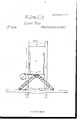
'tion of the construction and operation of the same, reference being had to the annexed drawings, making part of this specification, in which- Figure l on Sheet l is an isometrical projection of a complete press with the said improvements, and Fig. 2 on Sheet 2 ageometrical vertical section.`
"Ihe construction of the press is inthe usual manner, as shown in Figs. l and 2, consisting of upright posts A, top rails, B, "bottom rails, C, and intermediate and other rails,.D, furthermoie, of the box E an d follower F, the upper arms, G, and lower arms, II. The above letters have reference to Fig. 2 as well as Fig. l. 'Ihe rail-pieces D are on a level with the top of the lower arms, II, of the toggle-joint when they stand vertical, and between the said rail-pieces the pulleys are situated, as hereinafter described, for drawing up the togglo-joints.,w The length of the lower arms, II, is shorter than the upper arms, G-that is, they are made in such proportion to each other that when the lower` ones are in a horizontal position, as represented in Fig. 2, the upper arms shall be long enough to extend up above and clear of the pulleys, to their point of j unction with the follower F, directly over the stationaryjoint of levers II, in a vertical line. By this construction and these proportions the maximum motion and power is given to the arms that they are capable of receiving, said arms having the purchase that they are raised by placed at a stationary point between them on a level with the upper end of the arms H when they are standing vertical. Ropes pass round pulleys connected with the arms G H G II at their junction I, and those placed at the stationary point between the toggle-joints form the purchase above named. In Fig. l are shown the pulleys l 2 3 4, which revolve on the same pins I which connect the respective arms, and in the center of the frame, at the rail-pieces D', are introduced two sets of pulleys, each consisting of two pulleys, and which pulleys are marked 5, 6, 7, and `8. 0n the top of an addi.-
tional piece to the connecting-rail D and to a pin, K, inserted therein, is fastened a rope or chain, L, which passes over pulley 2, thence around pulley G, next over pulley I, returning to pulley 5, and liually to drum M. An.- other rope, N, Fig. l, is fastened to a pin, or bysoineother means, (not shown in the drawings,) at or near the center of rail D', and at its under side. This rope passes first round pulley 3, next over pulley 7, thence returning around pulley 4t, and then passing over pulley 8 to drum M, where it is astened, like the other rope. rlhe pulleys l, 2, 3, and 4t, as
above stated, are revolving on the saine pins that connect the arms, but are located between them, the arms being twin arms-viz., each consists of two separate pieces for the purpose of introducing said pulleys, and., furthermore, for the purpose of allowing the rope to pass between them. The drum M is furnished on one end with a crank for the application of the moving power. The ends of the b'ottom rails, G, above mentioned, extend beyond' the other stationary frame-work to such a length as to admit a sufiicient number of indentations or notches, p, for the reception of the lower endsotthe check-arms P, the upper ends of which are hung upon the pins I in the joint-s.
nIn Fig. 2, Sheet 2, the follower F is in its lowest position, and the lower arms, II, horizontal, and resting upon the bottom rail, C. The bottom arms in their motion describe one-4 fourth of a circle.`
The operation is as follows: Then the press is in the position shown at Fig. 2, and the box iilled with cotton or other material to be pressed, the power is applied to the drum M,
by which the joints I I, connecting the arms H G H G, are drawn up and inward. Through the intervention of the purchase connecting the joints I with the point D the whole strain of the pressure being borne by the ropes and pulleys; but as the arms are brought more nearly into a vertical position, the strain is gradn ally shifted, as the power of the arms increases, from the ropes to the arms, which, when brought vertical, sustain the whole pressure. It is proper here to remark that the toggle-joints on each side are acted upon by separate sets of pulleys, as will readily be seen by reference to the drawings, the ropes to which are connected to the same drum for the purpose of producing aparallel motion in the two sets of toggle-joints, so as to raise the follower level. The center pulleys may be either on two separate axes or on one common axis.
It will be understood that any additional number of pulleys may be used, or the number reduced, as circumstances may require to increase or lessen the purchase. The cheek.- arms l), Fig. 1, in consequence of their upper ends being hung to the pins I, as above described, will followthe movement of the arms G H at their joints, and their lower ends, falling into the indentations p of the bottom rail,
C, will not'only prevent the sliding back of the joints, which is very important in case one or both ropes should break.
I am aware that doubletogglc-joint presses have been constructed with a windlass stationed in the center between the said joints, and that pulleys have been used to draw to gether toggle-joints, in which lthe ropes extended straight across from the center joint of one to the center joint of the other. Togglejoints have also been made with arms of unequal length. Therefore, I do not claim either of these general principles; but
What l do claim as my invention, and de sire to secure by Letters Patent, is
The combination and arrangement of the' toggle-joints, as herein described, with the
Publications (1)
| Publication Number | Publication Date |
|---|---|
| US3631A true US3631A (en) | 1844-06-15 |
Family
ID=2063929
Family Applications (1)
| Application Number | Title | Priority Date | Filing Date |
|---|---|---|---|
| US3631D Expired - Lifetime US3631A (en) | X i improvement in |
Country Status (1)
| Country | Link |
|---|---|
| US (1) | US3631A (en) |
-
0
- US US3631D patent/US3631A/en not_active Expired - Lifetime
Similar Documents
| Publication | Publication Date | Title |
|---|---|---|
| US3631A (en) | X i improvement in | |
| US370259A (en) | eorba-czewski | |
| US1171393A (en) | Excavating apparatus. | |
| US379414A (en) | Baling-press | |
| US475117A (en) | Apparatus for baling cotton | |
| US137160A (en) | Improvement in apparatus for compressing cotton, hay | |
| US244272A (en) | John maeoh | |
| US1435082A (en) | Freight and passenger elevator | |
| US382269A (en) | price | |
| US1313228A (en) | minnich | |
| US420301A (en) | hoyey | |
| US5135A (en) | Improvement in cotton-presses | |
| US1798A (en) | Improvement in presses for cotton, hay | |
| US195747A (en) | Improvement in fire-escapes | |
| US1516A (en) | Machine for braking or working dough | |
| US144982A (en) | Improvement in hand-power baling-presses | |
| US328271A (en) | Kane adam | |
| US5632A (en) | Improvement in cotton-presses | |
| US142517A (en) | Improvement in cotton-presses | |
| US1128899A (en) | Portable clothes-reel. | |
| US290696A (en) | Cotton-press | |
| US84385A (en) | Improvement in elevators | |
| US228342A (en) | Tobacco-hoisting apparatus | |
| US94602A (en) | Improvement in cotton and hay-presses | |
| US94257A (en) | Isaac h |