US3629635A - Wheel-speed sensor for an adaptive braking system - Google Patents
Wheel-speed sensor for an adaptive braking system Download PDFInfo
- Publication number
- US3629635A US3629635A US42402A US3629635DA US3629635A US 3629635 A US3629635 A US 3629635A US 42402 A US42402 A US 42402A US 3629635D A US3629635D A US 3629635DA US 3629635 A US3629635 A US 3629635A
- Authority
- US
- United States
- Prior art keywords
- wheel
- pole piece
- vehicle
- tone
- speed sensor
- Prior art date
- Legal status (The legal status is an assumption and is not a legal conclusion. Google has not performed a legal analysis and makes no representation as to the accuracy of the status listed.)
- Expired - Lifetime
Links
Images


Classifications
-
- G—PHYSICS
- G01—MEASURING; TESTING
- G01P—MEASURING LINEAR OR ANGULAR SPEED, ACCELERATION, DECELERATION, OR SHOCK; INDICATING PRESENCE, ABSENCE, OR DIRECTION, OF MOVEMENT
- G01P3/00—Measuring linear or angular speed; Measuring differences of linear or angular speeds
- G01P3/42—Devices characterised by the use of electric or magnetic means
- G01P3/44—Devices characterised by the use of electric or magnetic means for measuring angular speed
- G01P3/48—Devices characterised by the use of electric or magnetic means for measuring angular speed by measuring frequency of generated current or voltage
- G01P3/481—Devices characterised by the use of electric or magnetic means for measuring angular speed by measuring frequency of generated current or voltage of pulse signals
- G01P3/488—Devices characterised by the use of electric or magnetic means for measuring angular speed by measuring frequency of generated current or voltage of pulse signals delivered by variable reluctance detectors
Definitions
- a wheel-speed sensor utilizing a magnetic pickup and adapted for use on an automotive vehicle A cupshaped drive wheel has an elastomeric friction ring secured to the inside surface of the rim of the cup.
- the friction ring drives a driven wheel and tone wheel element of an assembly including a pickup whose components are assembled on a unitary plastic molding which also serves as the bobbin for the coil.
- the mounting element of the driven wheel and pickup is a unitary stamping attached to a nonrotatable portion of the vehicle.
- This invention relates to an adaptive braking system for use on an automobile. More specifically, it relates to the wheelspeed sensor which provides the adaptive braking system with information relative to the speed and acceleration of one of the several wheels of an automotive vehicle.
- An adaptive braking system of the type in which the invention would be used is described in U.S. Pat. No. 3,494,671. Wheel-speed sensors of the game general class and of which this is an improvement are described in U.S. Pat. application Ser. Nos. 42,112, filed June 1, I970, and 42,111 filed June I, I970, having in common with this application the same assignee.
- An object of the invention is to provide a wheel-speed sensor of the general type which can be readily and economically produced with conventional equipment by eliminating operations that are costly in labor such as cementing and post-assembly finishing.
- the invention discloses a drive wheel which can be substantially formed by a single stroke of a press.
- the invention includes a pickup for the sensor in which a unitary plastic molding serves not only as the usual coil-winding bobbin, but also has provision for the permanent attachment of the coil terminals.
- the permanent magnet and the ferromagnetic pole piece are received and held in their relative positions prior to final assembly into the outer housing.
- the outer housing of the pickup may be an integral portion of the structural elements which support and combine the other elements of the sensor, such as the tone wheel.
- the structural elements which comprise a spring section and mounting bracket may all be combined into a single integral sheet steel stamping.
- FIG. 4 is an enlarged sectional view showing in detail the structure of the tone wheel, driven wheel, pickup assembly.
- FIG. 5 is a sectional view taken on line 55 of FIG. 4.
- FIG. 6 is a plane view of the subassembly showing the integral stamping that constitutes the structural elements including the spring and mounting bracket of the sensor and the shaft for the driven wheel, tone wheel element.
- FIG. 7 is an elevational view of the subassembly of FIG. 6.
- FIG. 8 is a view of the plastic molding of the pickup assembly.
- FIG. 9 is a sectional view along line 9-9 of FIG. 8.
- FIG. 10 is a sectional view along line I0l0 of FIG. 8.
- FIG. 11 is an elevational view of the cup-shaped element of the drive wheel.
- FIG. 12 is a sectional view taken on the line 12-12 of FIG. I 1.
- FIG. 13 is a partial enlarged section of the cup-shaped element in the same plane as FIG. 12.
- FIG. 14 is a view similar to FIG. 13 but with the elastomeric friction ring in place.
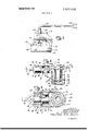
- FIGS. 1 and 2 show a conventional rear axle housing 10 containing an axle 12 formed with a flange 14, into which are pressed the usual wheel mounting bolts 16.
- a brake backing plate I8 to which are attached the usual parts of a brake such as the shoes 20, is mounted by bolts 22 and nuts 24 to a flange 26 of the axle housing 10.
- the outer face of the axle flange I4 is formed with a pilot projection 28 which usually is made accurately concentric with the bearing surfaces 29 of the axle 12.
- the central bore 31 of a brake drum 30 pilots on the projection 28 and the drum 30 is held in place by being clamped between the wheel (not shown) and the axle flange 14.
- a driven wheel, tone wheel, pickup assembly indicated generally by the numeral 32.
- a bracket portion 34 is attached to the axle housing 10 by removing two of the nuts 24, placing the two mounting holes of the bracket 34 over the screws 22 and replacing the nuts 24.
- a C-shaped leaf spring element 36 and structural elements 38 for mounting the tone .wheel, driven wheel 45 and pickup are illustrated as comprising integral parts of a single stamping 40 made from ferromagnetic material such as sheet steel.
- the structural elements 38 are formed generally in the shape of a box with one open side and one open end. The side of the box opposite the open side is extended lengthwise from the open end with a shallow U-section for strength to provide an arm 42 into which is riveted a shaft 43.
- the detailed structure of the stamping 40 can be clearly seen in FIGS. 6 and 7 which show the stamping 40 in subassembly with the shaft 43.
- the driven wheel 45 is a generally cylindrical element 44 having a flange at one end formed with teeth resembling gear teeth to constitute the signal-generating elements of the tone wheel 46.
- the tone wheel, driven wheel 45 is an integral structure which may be machined from a bar of ferromagnetic material such as steel. Ferromagnetic material is required since the teeth or signal-generating elements must be of such material.
- the tone wheel, driven wheel 45 is formed with a through bore 48 in which is pressed a roller bearing 50 rotatably seated on the shaft 43.
- the bore 48 has enlarged portions at each end. The one at the top, as seen in FIG. 4, receives a pressed-in dirt excluding seal 52 and retainer 53 which also engages the shaft 43.
- the enlarged portion of the bore 48 at the bottom, as seen in FIG. 4, has pressed into it a ball bearing 54 which is seated against a shoulder 56 and held by a pressed-in cup-shaped stamping 58 which closes the open end of the bore 48. After this cup 58 is installed, it is sealed by the application of sealing compound 60.
- the inner race of the ball bearing 54 is mounted on a reduced diameter portion 62 of the shaft 43 and is held against a shoulder 64 by a washer 66 and a rivet-formed shoulder 68. It will be seen that, thus installed, the ball bearing 54 forms an axial positioner and thrust taker for the driven wheel 45.
- the pickup indicated generally by the numeral 70 and consisting of a coil 72, suitable wiring harness 74 (shown in FIG. 3), a permanent magnet 76 and a pole piece 78, is positioned in the box-shaped portion of the structural elements 38 with the pole piece 78 projecting at the open end into proximity with the teeth of the tone wheel 46, and is secured in place by application of potting compound. If a removable shim of suitable dimensions is placed between the pole piece 78 and the tone wheel 46 while the potting compound is hardening, a permanent fixed clearance will be established.
- FIGS. 8, 9 and 10 show three views of the plastic molding 80.
- the molding 80 includes a coil-forming or bobbin section 82 which surrounds a rectangular central opening 84 designed to receive in close fitting engagement the pole piece 78, and a circular cylindrical recess 86, extending from one end in alignment with the opening 84, designed to receive and accurately position the permanent magnet 76.
- the magnet 76 is preferably made of a suitable high-energy magnetic alloy.
- the pole piece 78 is T-shaped with a head 88 which seats against the shoulder 90 which forms the transition from the rectangular opening 84 to the circular recess 86.
- FIG. 5 also illustrates how the pole piece 78 is formed with two teeth 79 spaced equally with the teeth of the tone wheel 46.
- a pair of coil terminal fittings 98 are crimped into the slots 92 and extend into the recesses 96 to be connected in compact manner with the coil leads of the wiring harness 74.
- the wiring harness as shown in FlGS. 1, 2 and 3, is provided with a molded elastomeric grommet 100 which passes through a suitable hole 102 in the brake backing plate 18.
- the hole 102 is made large enough to pass through the permanently attached terminal fittings 104 at the other end of the wiring harness.
- the terminal fittings 104 are, in turn, attached to wiring harness (not shown) leading to other components of the adaptive braking system.
- a friction drive wheel 106 is provided in the form of a large cupshaped element 108 (shown in FIGS. 11, 12 and 13).
- the cup 108 consists of a flat bottom portion 110 having a central opening 112 which fits closely over the pilot projection 28 of the axle 12.
- cylindrical parts 114 are of greater diameter than the axle flange 14 so that the cup 108 can be readily placed thereover with the inner margin of the cylindrical parts inside the vehicle brake.
- This inner margin is formed with a groove or channel 116 which opens inwardly, i.e., toward the centerline of the axle, and an elastomeric friction drive ring 118 of generally square cross section is seated in this groove.
- one sidewall 120 is formed with a multiplicity of equally spaced lanced-in portions which forms fingers or projections 122 disposed in a manner to resist withdrawal of the ring 118.
- the other sidewall 124 of the groove is crimped inwardly about the entire circumference of the cup 108. This can be seen more clearly by reference to FlG. 14.
- Other ways of deforming the sidewalls 120 and 124 of the groove 116 to positively secure the ring 118 may be envisioned within the spirit of the invention.
- the spring 36 supports and positions the driven wheel, tone wheel and pickup assembly 32 into tight but resilient contact with the inner surface of the friction ring 118 so that the tone wheel, driven wheel 45 is rotated at very high speed.
- the tone wheel As the tone wheel is rotated, its teeth are alternately aligned and not aligned with the teeth of the pole piece 78 causing a variation of magnetic flux therein and inducing an alternating voltage in the pickup coil 72 which is transmitted via the wiring harness 74 to the computer of the adaptive braking system.
- a wheel-speed sensor for use on a vehicle wheel having a rotatable portion and a nonrotatable portion, said sensor comprising:
- said friction drive wheel including an inwardly opening groove formed on an inner margin, a friction ring secured in the groove by crimping the groove walls into said groove, a plurality of fingers formed in the inner wall of said groove for said crimping of said groove walls to hold the friction ring in place, and a cup-shaped portion for extending the friction ring over a flange portion of an axle of said vehicle wheel.
- said structural means are an integral stamping formed from a sheet of metallic material.
- a wheel-speed sensor for use on a wheel of a vehicle, said sensor comprising:
- a friction drive wheel mounted for rotation with said vehicle wheel
- resilient means yieldably urging said rigid link toward said drive wheel, said resilient means yieldably maintaining said driven wheel in engagement with said drive wheel.
- said resilient means being a generally C-shaped leaf spring presenting a pair of arms
- one of said arms being secured to said nonrotative portion of the vehicle
- said pickup means including a permanent magnet, a pole piece connected to said permanent magnet and in close proximity with said tone wheel, a coil operatively connected to said pole piece to determine magnetic flux variations therein, and a molded element for combining said permanent magnet, pole piece and coil into a compact, unitary structure.
- said pickup means further includes notches in the end of said pole piece, said notches being alternately aligned and not aligned with said tone wheel to produce maximum and minimum magnetic flux in said pole piece, respectively.
- a center bore to receive said pole piece and means to prevent said pole piece from moving once positioned; and a cylindrical recess for receiving and positioning said permanent magnet.
Landscapes
- Physics & Mathematics (AREA)
- General Physics & Mathematics (AREA)
- Regulating Braking Force (AREA)
- Braking Arrangements (AREA)
Applications Claiming Priority (3)
| Application Number | Priority Date | Filing Date | Title |
|---|---|---|---|
| US4211270A | 1970-06-01 | 1970-06-01 | |
| US4211170A | 1970-06-01 | 1970-06-01 | |
| US4240270A | 1970-06-01 | 1970-06-01 |
Publications (1)
| Publication Number | Publication Date |
|---|---|
| US3629635A true US3629635A (en) | 1971-12-21 |
Family
ID=27366051
Family Applications (3)
| Application Number | Title | Priority Date | Filing Date |
|---|---|---|---|
| US42402A Expired - Lifetime US3629635A (en) | 1970-06-01 | 1970-06-01 | Wheel-speed sensor for an adaptive braking system |
| US42111A Expired - Lifetime US3626224A (en) | 1970-06-01 | 1970-06-01 | Wheel speed sensor for an adaptive braking system having a rotating tone wheel and electromagnetic pickup means |
| US42112A Expired - Lifetime US3626225A (en) | 1970-06-01 | 1970-06-01 | Wheel speed sensor for an adaptive braking system having a rotatable tone wheel and electromagnetic pickup means |
Family Applications After (2)
| Application Number | Title | Priority Date | Filing Date |
|---|---|---|---|
| US42111A Expired - Lifetime US3626224A (en) | 1970-06-01 | 1970-06-01 | Wheel speed sensor for an adaptive braking system having a rotating tone wheel and electromagnetic pickup means |
| US42112A Expired - Lifetime US3626225A (en) | 1970-06-01 | 1970-06-01 | Wheel speed sensor for an adaptive braking system having a rotatable tone wheel and electromagnetic pickup means |
Country Status (5)
| Country | Link |
|---|---|
| US (3) | US3629635A (fr) |
| CA (3) | CA941046A (fr) |
| DE (1) | DE2127115A1 (fr) |
| FR (1) | FR2093939B1 (fr) |
| GB (1) | GB1301622A (fr) |
Cited By (1)
| Publication number | Priority date | Publication date | Assignee | Title |
|---|---|---|---|---|
| US3761751A (en) * | 1971-03-19 | 1973-09-25 | Itt | Mounting arrangement for wheel speed sensors |
Families Citing this family (13)
| Publication number | Priority date | Publication date | Assignee | Title |
|---|---|---|---|---|
| DE7245640U (de) * | 1971-12-14 | 1973-11-08 | Fiat Spa | Meßgerat zur Feststellung der Winkelgeschwindigkeit eines Kraftfahr zeugrades |
| US3844168A (en) * | 1973-08-03 | 1974-10-29 | Gen Electric | Torque measuring apparatus |
| US4110676A (en) * | 1976-08-30 | 1978-08-29 | Reliance Electric Company | Dynamoelectric machine and tachometer |
| CA1262753A (fr) * | 1984-05-09 | 1989-11-07 | Tsutomu Hayashi | Mecanisme anticalage des freins de vehicules |
| US4700133A (en) * | 1986-02-28 | 1987-10-13 | Ssi Technologies, Inc. | Variable reluctance magnetic sensor with pole piece and shell projections matched to gear teeth |
| US4937522A (en) * | 1988-08-29 | 1990-06-26 | Eaton Corporation | Speed sensor pickup assembly with slotted magnet |
| GB9024283D0 (en) * | 1990-11-08 | 1990-12-19 | Lucas Ind Plc | Internal shoe drum brake |
| US6131547A (en) * | 1998-02-27 | 2000-10-17 | Cummins Engine Company, Inc. | Electronic engine speed and position apparatus for camshaft gear applications |
| CN1272758C (zh) * | 2000-11-09 | 2006-08-30 | Lg电子株式会社 | 能够提升电压的能量回收电路及其提高能效的方法 |
| US6987338B1 (en) | 2003-12-29 | 2006-01-17 | Lavasser Leonard J | Ground strap for a motor having a plastic housing |
| DE202010011721U1 (de) | 2010-08-24 | 2010-10-21 | Manitowoc Crane Group France Sas | Radialspielausgleichende Drehwinkelgeberanordnung |
| US9948496B1 (en) | 2014-07-30 | 2018-04-17 | Silver Peak Systems, Inc. | Determining a transit appliance for data traffic to a software service |
| US10156240B2 (en) | 2016-06-16 | 2018-12-18 | Scott C. Mancl | Motor-driven fan with trapped adhesive for minimizing vibration |
Citations (7)
| Publication number | Priority date | Publication date | Assignee | Title |
|---|---|---|---|---|
| US1797579A (en) * | 1928-09-24 | 1931-03-24 | Roscoe C Hoffman | Motor vehicle |
| USRE22549E (en) * | 1944-09-26 | Electric motor | ||
| FR1336035A (fr) * | 1962-10-17 | 1963-08-23 | Lucas Industries Ltd | Générateur de courant alternatif |
| US3447838A (en) * | 1967-12-06 | 1969-06-03 | Jacobs Mfg Co | Antiskid system for motor vehicles having airbrakes |
| US3469135A (en) * | 1967-03-24 | 1969-09-23 | Hammond Corp | Tone signal generator |
| US3482130A (en) * | 1967-12-28 | 1969-12-02 | Ford Motor Co | Reluctance pickup speed device for a speedometer cable |
| US3509395A (en) * | 1968-11-25 | 1970-04-28 | Hammond Corp | Tone signal generator |
Family Cites Families (8)
| Publication number | Priority date | Publication date | Assignee | Title |
|---|---|---|---|---|
| US555492A (en) * | 1896-03-03 | Speed-indicator for bicycles | ||
| GB812553A (en) * | 1955-07-28 | 1959-04-29 | Dunlop Rubber Co | Rotary inertia device and fluid braking system |
| US2798976A (en) * | 1954-12-02 | 1957-07-09 | Rca Corp | Timing signal generator |
| FR1267910A (fr) * | 1960-06-15 | 1961-07-28 | Renault | Perfectionnement aux génératrices tachymétriques |
| US3198973A (en) * | 1961-03-13 | 1965-08-03 | Gen Motors Corp | Distributor having magnetic pick-up coil |
| US3280934A (en) * | 1964-09-21 | 1966-10-25 | Biasi Charles P De | Auto kinetic wheel or fluid motor |
| US3315544A (en) * | 1964-12-07 | 1967-04-25 | Axel Wickman Transmissions Ltd | Vehicular driving axle |
| US3482129A (en) * | 1968-07-25 | 1969-12-02 | Kelsey Hayes Co | Inductor generator with self-lubricating bearing and constant air gaps for sensing vehicle wheel speed |
-
1970
- 1970-06-01 US US42402A patent/US3629635A/en not_active Expired - Lifetime
- 1970-06-01 US US42111A patent/US3626224A/en not_active Expired - Lifetime
- 1970-06-01 US US42112A patent/US3626225A/en not_active Expired - Lifetime
-
1971
- 1971-02-18 CA CA105,717A patent/CA941046A/en not_active Expired
- 1971-02-18 CA CA105,719A patent/CA961569A/en not_active Expired
- 1971-03-03 CA CA106,786A patent/CA941047A/en not_active Expired
- 1971-05-17 GB GB1530271*[A patent/GB1301622A/en not_active Expired
- 1971-05-27 FR FR7119227A patent/FR2093939B1/fr not_active Expired
- 1971-06-01 DE DE19712127115 patent/DE2127115A1/de active Pending
Patent Citations (7)
| Publication number | Priority date | Publication date | Assignee | Title |
|---|---|---|---|---|
| USRE22549E (en) * | 1944-09-26 | Electric motor | ||
| US1797579A (en) * | 1928-09-24 | 1931-03-24 | Roscoe C Hoffman | Motor vehicle |
| FR1336035A (fr) * | 1962-10-17 | 1963-08-23 | Lucas Industries Ltd | Générateur de courant alternatif |
| US3469135A (en) * | 1967-03-24 | 1969-09-23 | Hammond Corp | Tone signal generator |
| US3447838A (en) * | 1967-12-06 | 1969-06-03 | Jacobs Mfg Co | Antiskid system for motor vehicles having airbrakes |
| US3482130A (en) * | 1967-12-28 | 1969-12-02 | Ford Motor Co | Reluctance pickup speed device for a speedometer cable |
| US3509395A (en) * | 1968-11-25 | 1970-04-28 | Hammond Corp | Tone signal generator |
Cited By (1)
| Publication number | Priority date | Publication date | Assignee | Title |
|---|---|---|---|---|
| US3761751A (en) * | 1971-03-19 | 1973-09-25 | Itt | Mounting arrangement for wheel speed sensors |
Also Published As
| Publication number | Publication date |
|---|---|
| GB1301622A (fr) | 1973-01-04 |
| CA941046A (en) | 1974-01-29 |
| FR2093939A1 (fr) | 1972-02-04 |
| US3626224A (en) | 1971-12-07 |
| FR2093939B1 (fr) | 1975-07-04 |
| CA941047A (en) | 1974-01-29 |
| CA961569A (en) | 1975-01-21 |
| US3626225A (en) | 1971-12-07 |
| DE2127115A1 (de) | 1971-12-23 |
Similar Documents
| Publication | Publication Date | Title |
|---|---|---|
| US3629635A (en) | Wheel-speed sensor for an adaptive braking system | |
| US3719841A (en) | Wheel speed sensors for vehicle adaptive braking systems | |
| US3626226A (en) | Wheel speed sensor for an adaptive braking system | |
| CA2114064C (fr) | Capteur de vitesse de roulement pour vehicules, monte sur chapeau de moyeu | |
| US3626227A (en) | Wheel speed sensor for an adaptive braking system | |
| US4027753A (en) | In-axle vehicle wheel speed sensing device | |
| US3910386A (en) | Quick installation vehicle wheel sensor | |
| ES2000719A6 (es) | Freno de discos para motor electrico | |
| US5281911A (en) | Vehicle wheel speed sensor employing a locating plate | |
| GB2197991A (en) | Disc drive electric motor yoke/disc support | |
| EP0701133A1 (fr) | Ensemble de roulement avec capteur de vitesse de rotation | |
| US3772548A (en) | Wheel speed sensor | |
| US4510408A (en) | Mounting device for cylindrical magnetic sensor | |
| US3626228A (en) | Wheel speed sensor for an adaptive braking system | |
| US6315088B1 (en) | Spring-set electromagnetically released brake | |
| US3939373A (en) | Fixed gap speed sensor | |
| US3653471A (en) | Installation for the brake-locking prevention in vehicles | |
| US3915266A (en) | In axle wheel speed sensor for anti-skid brake control | |
| US3876048A (en) | Electromagnetic clutch | |
| US3949252A (en) | Vehicle wheel rotation speed measuring system | |
| US3927339A (en) | Frequency transmitters for producing control signals controlling the brake force in motor vehicle wheels | |
| US4037690A (en) | Sensor module bracket | |
| US3769534A (en) | Wheel speed sensor | |
| US3774061A (en) | Wheel speed sensor | |
| US3719840A (en) | High frequency transmitter,especially for brake slippage control installation of motor vehicles |