US3621348A - Control system for automatic operation of a press line - Google Patents
Control system for automatic operation of a press line Download PDFInfo
- Publication number
- US3621348A US3621348A US838900A US3621348DA US3621348A US 3621348 A US3621348 A US 3621348A US 838900 A US838900 A US 838900A US 3621348D A US3621348D A US 3621348DA US 3621348 A US3621348 A US 3621348A
- Authority
- US
- United States
- Prior art keywords
- synchro
- generator
- presses
- press
- press line
- Prior art date
- Legal status (The legal status is an assumption and is not a legal conclusion. Google has not performed a legal analysis and makes no representation as to the accuracy of the status listed.)
- Expired - Lifetime
Links
Images

Classifications
-
- H—ELECTRICITY
- H02—GENERATION; CONVERSION OR DISTRIBUTION OF ELECTRIC POWER
- H02P—CONTROL OR REGULATION OF ELECTRIC MOTORS, ELECTRIC GENERATORS OR DYNAMO-ELECTRIC CONVERTERS; CONTROLLING TRANSFORMERS, REACTORS OR CHOKE COILS
- H02P5/00—Arrangements specially adapted for regulating or controlling the speed or torque of two or more electric motors
- H02P5/46—Arrangements specially adapted for regulating or controlling the speed or torque of two or more electric motors for speed regulation of two or more dynamo-electric motors in relation to one another
- H02P5/50—Arrangements specially adapted for regulating or controlling the speed or torque of two or more electric motors for speed regulation of two or more dynamo-electric motors in relation to one another by comparing electrical values representing the speeds
-
- B—PERFORMING OPERATIONS; TRANSPORTING
- B21—MECHANICAL METAL-WORKING WITHOUT ESSENTIALLY REMOVING MATERIAL; PUNCHING METAL
- B21D—WORKING OR PROCESSING OF SHEET METAL OR METAL TUBES, RODS OR PROFILES WITHOUT ESSENTIALLY REMOVING MATERIAL; PUNCHING METAL
- B21D43/00—Feeding, positioning or storing devices combined with, or arranged in, or specially adapted for use in connection with, apparatus for working or processing sheet metal, metal tubes or metal profiles; Associations therewith of cutting devices
- B21D43/02—Advancing work in relation to the stroke of the die or tool
- B21D43/04—Advancing work in relation to the stroke of the die or tool by means in mechanical engagement with the work
- B21D43/05—Advancing work in relation to the stroke of the die or tool by means in mechanical engagement with the work specially adapted for multi-stage presses
-
- B—PERFORMING OPERATIONS; TRANSPORTING
- B30—PRESSES
- B30B—PRESSES IN GENERAL
- B30B15/00—Details of, or accessories for, presses; Auxiliary measures in connection with pressing
- B30B15/14—Control arrangements for mechanically-driven presses
- B30B15/146—Control arrangements for mechanically-driven presses for synchronising a line of presses
-
- B—PERFORMING OPERATIONS; TRANSPORTING
- B30—PRESSES
- B30B—PRESSES IN GENERAL
- B30B15/00—Details of, or accessories for, presses; Auxiliary measures in connection with pressing
- B30B15/14—Control arrangements for mechanically-driven presses
- B30B15/148—Electrical control arrangements
Definitions
- each of the components of the press line is operated in synchronism so that accurate timing is maintained between the sliding motions of the presses and the associated transfer feeders.
- the method of operating the press line for obtaining the goodtiming betweenthe component members of the press line is of the fundamental importance.
- the conventional method employed for operating a press line employs presses, each having a specifically assigned working region, and transfer feeders interposed between each of the presses. They are operated so that each workpiece processed in a press is taken out of the press, transferred and loaded into the next press. In such conventional methods all of the presses stopped their operations once in each operational cycle and aligned their positions to, for instance, their upper dead points.
- the object of this invention is to provide an improved method of operating a press line, wherein the above-described drawbacks of the conventional method are eliminated.
- Principle object of the invention is to provide an improved method for operating a press line, wherein the necessity of aligning the positions once in each of the operational cycle is obviated.
- Another object of this invention is to provide a novel method for controlling a press line, wherein the life of the clutches and the like is elongated and the operational procedure thereof simplified.
- Still another object of the present invention is to provide a novel method for controlling a press line, wherein all the presses and the transfer feeders are equipped with variable speed motors, and the sliding motion of each of the presses and the translating motion of each of the transfer feeders are interlinked synchronously by combining them electrically, so that the press line can be operated synchronously.
- a novel method for operating the press line including a row of presses each having a specific working region assigned thereto and a required number of transfer feeders interposed between each of the presses.
- the method comprised the steps of controlling, before the activation of thepresses, flywheel driving motors of the presses with the aid of a reference tachometer generator and controlling tachometer generators attached on the presses so that the speeds of the flywheel driving motors are substantially equal to each other.
- the flywheel driving motors are driven in synchronism by the aid of a reference synchro-generator and control synchro-motor attached on the presses.
- FIG. 2 is a schematic diagram of a press line for which an embodiment of the operational method of the invention is applied.
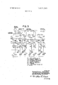
- FIG. 3 is a similar schematic diagram of another press line for which another embodiment of the operational method of the invention is to be applied.
- the solid line shows the electrical connections
- the broken line shows the mechanical connections.
- the press line according to the present invention comprises a plurality of single acting presses 1, 2, 3, and 4, each of which is operable independently, and a plurality of transfer feeders 5, 6, 7 and 8, each of which is interposed between the preceding press and the following press, so that each of workpieces loaded in a press is worked therein, unloaded, transported to the next press, and loaded therein automatically.
- a piece of material initially loaded in the first press 1 is pressed therein.
- the thus pressed material in the first press 1 is thereafter taken out of the first press 1 automatically by means of the first transfer feeder 5 and transported to the second press 2 to be loaded therein.
- the material is again pressed in the second press 2, unloaded and transported automatically to the third press 3 by means of the second transfer feeder 6.
- the material is thus loaded in the third press 3.
- the presses I, 2, 3 and 4 are operated in synchronism.
- all the motors for driving the presses 1, 2, 3 and 4 have their speeds equalized by tachometer generators provided on each of the presses and also by tachometer generator provided separately.
- the motors for driving the flywheels of the presses are synchronized by means of control synchro-motors provided on the presses and a master synchro-generator provided in a separate position. In this way, unloading of the workpieces from all of the presses, transportation of these workpieces to the following presses, and loading of these pieces in the presses, can be carried out fully automatically.
- an AC motor 16 which is supplied power from an AC power source 13 through a disconnect switch 14 and a control switch 15.
- a fuse 17, a transfonner 18 for energizing the control switch 15, a protecting relay 19, an AC ammeter 20, and a current transformer 21 are also provided at the input of the AC motor 16.
- DC motors 9, 10, 11 and 12 for driving the presses 1, 2, 3 and 4, respectively. They are all supplied power from the DC generator 22 through circuit interrupters 30a, 30b, 30c and 30d, reversible magnetic switches 31a, 31b, 31c and 31d, thermal overload relays 32a, 32b, 32c and 32d, and a starting resistors resistors 33a, 33b, 33c and 33d, respectively.
- the field current flowing through magnetic field coils 34a, 34b, 34c and 34d of these motors 9, l0, l1 and 12 are regulated by corresponding magnetic field control amplifiers 35a, 35b, 35c and 35d, respectively.
- Tachometer generators 36a, 36b, 36c and 36d are also attached on the presses 1, 2, 3 and 4.
- Transistor relays 37a, 37b, 37c and 37d, are connected to the former for confirming the stop of the motors 9, 10, 11 and 12, respectively.
- a DC motor 38 for driving a reference synchro-generator 44 to be used for synchronizing the presses 1, 2, 3 and 4.
- the motor 38 receives electric power from the DC generator 22 through a magnetic switch 39 and a thermal overload relay 40.
- a tachometer generator 41 is directly coupled to the DC motor 38.
- the output of the tachometer generator 41 is compared with the outputs of the tachometer generators 36a, 36b, 36c and 36d directly coupled with the DC motors 9, 10, 11 and 12 for driving the flywheels of the presses.
- the difference therebetween is amplified in the respective field control amplifier 35a, 35b, 35c and 35d so that a current proportional to the difference is passed through the field coil 34a, 34b, 34c and 34d. In by this way, the rotating speed of the motors 9, 10, 11 and 12 are equalized before the presses 1, 2, 3 and 4 are put into operation.
- Phase differences between the control synchro-motors 43a, 43b, 43c and 43d and the reference synchro-generator 44 are detected and amplified by synchronism detecting amplifiers 46a, 46b, 46c, and 46d.
- the results are transmitted to the field control amplifiers 35a, 35b, 35c and 35d, respectively, whereby the rotating speeds of the DC motors 9, 10, 11 and 12 may be equalized between each other.
- speed reduction means 47a, 47b, 47c and 47d are provided between the clutches 42a, 42b, 42c and 42d and the synchro-motors 43a, 43b, 43c and 43d, respectively.
- indicating synchro-transmitters 48a, 48b, 48c and 48d which are in turn directly connected with indicating synchro-receivers 49a, 49b, 49c, and 49d respectively.
- These synchro-receivers 49a, 49b, 49c and 49d receive the output signals from the synchro-transmitters 48a, 48b, 48c and 48d and indicate the sliding position of the presses 1, 2, 3 and 4.
- Phase difference indicators 50a, 50b, 50c, and 50d and relays 51a, 51b, 51c and 51d are provided nearby the synchronism detecting amplifiers 46a, 46b, 46c, and 46d, and the phase differences between the reference synchro-generator 44 and the synchro-motors 43a, 43b, 43c and 43d are indicated by the former indicators.
- the phase difference between the reference synchro-generator 44 and any one of the synchro-motors exceeds an allowable limit, the corresponding relay is operated, and the power supply to the DC motors 9, 10, l l and 12 is interrupted so that all of the presses 1, 2, 3 and 4 are brought to standstill simultaneously.
- the rotating speeds of the flywheels driving motors 9, 10, 11 and 12 are equalized each other under the control of the tachometer generators 36a, 36b, 36c and 36d directly coupled to the flywheel driving motors and a reference tachometer generator 41 directly coupled to the reference motor 38 before the presses 1, 2, 3 and 4 are operated.
- the presses are driven in synchronism by the aid of the control synchro-motors and the reference synchro-generator, so that the loading, unloading, and transfer of the materials between the presses can be achieved in far simpler manner.
- the provision of the DC flywheel driving motors and a DC generator to supply electric power to these m0- tors allows mutual transfer of electric power between these DC motors.
- the required capacity for the DC generator can be substantially reduced.
- FIG. 3 there is illustrated another synchronizing control system which is adapted to be employed in another type of synchronizing control method of press line constituting another embodiment of the present invention.
- a plurality of transfer feeders are operated in synchronism under the control of a synchro-generator directly coupled to the first press, and the second and the following presses are operated continuously and intermittently so that these presses do not interfere with the operation of the first press and the transfer feeders.
- FIG. 3 there are indicated a first, second, third, n-th presses 101,, 101,, 101,, and transfer feeders 102,, 102,, 102,, which are interposed between each of the presses, and a feeder placed at the delivery side of the n-th press 101,,.
- the press line is formed from the presses 101 101,, and transfer feeders 102,, 102,, 102,,,, disposed in a linear arrangement.
- variable speed motors 105,, 105,, 105 For the purpose of operating the main variable speed motor 105, for the first press 101, at an equivalent speed to that of another variable speed motor 104 which is driving a master synchro-generator 103, each of the variable speed motors 105, and 104 are provided with a tachometer generator.
- the first press 101, of this embodiment may be a double acting press.
- the transfer feeders 102,, 102,, 102, are driven variable speed motors 106,, 106 106,,.
- the purpose of these variable speed motors operating at an equivalent speed to that of the variable speed motor 104 which is driving the master synchro-generator 103, all of the variable speed motors 106,, 106 106,, are provided with tachometer generators 107,, 107 107,, respectively.
- a synchro-generator 110 and a control synchro-receiver 111 as well as a tachometer generators 108, 109 are provided on the variable speed motors 104 and 105,.
- tachometer generators 108, 107,, 107,, 107,, a synchro-generator 103, and control synchroreceiver 112,, 112,, 112, are provided on the variable speed motors 104 and 106,, 106,, 106,.
- a rotary carn switch 113 is directly coupled to the master synchro-generator 103 so that they may be rotated in unison, and when the rotary cam switch 113 is rotated for a predetermined angle, the second and following presses 101, to 101, are started their operations through the activation of respective clutches.
- clutches 114, 115,, 115,, 115,, and 116,, 116,, 116 are also provided on the variable speed motors 104, 105,, 105,, 105,, and 106,, 106,, 106,.
- a single-interlink" operation transferring switch 117 is provided for the variable speed motor 105, for driving the first press 101, which is of double-acting type.
- Single-interlinked operation transfer switches 118,, 118,, 118, are further provided for the variable speed motors driving transfer feeders 107,, 107,, 107,.
- variable speed motor 104 is also provided with a speed control device 119, and the first press driving motor 105, is provided with another speed control device 120.
- variable speed motors 106,, 106,, 106, for driving the transfer feeders are provided with speed control devices 121,, 121,, 121,.
- numeral 127 designates a starting signal transmitter to be employed for engaging or disengaging the above described clutches 114, 115,, and 116,, 116,, 116,
- numeral 128 designates an electric power source.
- all of the solid lines indicate electrical connections, and the broken lines indicate mechanical connections.
- the clutches 114, 115,, 116,, 116,, 116, 116 are all engaged, whereby the master synchro-generator 103, the first press 101,, and the transfer feeders 102,, 102,, 102, are operated simultaneously.
- the variable speed motor 105, for the first press is controlled by the tachometer generator 108, 109, synchro-generator 110, a control synchro-receiver 111 so that the motor 105, operates at an equivalent speed and phase angle to those of the master synchro-generator 103.
- variable speed motors 106, 106,, 106, for driving the transfer feeders 102,, 102,, 102, are also controlled by the tachometer generators 108, 107,, 107,, and synchro-receiver 112,, 1 12,, 112, so that they are operated at an equivalent speed and phase angle to those of the master synchro-generator 103.
- the rotary cam switch 113 rotated in unison with the master synchro-generator 103 starts to operate the second and the following presses 101,, 101, in an appropriate timing, so that the second and the following presses 101,, 101, are started after the first press 101, and the transfer feeders 102,, 102,, 102, have brought into synchronized operation with the master synchro-generator 103.
- the second and the following presses 101,, 101 are started after the first press 101, and the transfer feeders 102,, 102,, 102, are all brought into synchronized operation with the master synchro-generator 103.
- the single interlink" transfer switch 117 for the first press 101 is thrown to the single" side, whereby the transfer feeders 102,, 102,, 102, and the second and the following presses can be controlled by the master synchro-generator 103 independently to the speed and phase angle of the first press 101,.
- an operational method of the control system constituting another embodiment of the present invention is made realizable, wherein the first press and all of the transfer feeders are maintained in a continuous operating condition, and, when it is required, the second and following presses are temporarily stopped, for instance, at their upper dead points, so that all of the presses and the transfer feeders are thereafter operated in synchronism.
- a control system for automatic operation of the press line comprising, a reference synchro-generator, a synchro-receiver, said synchro-receiver being operated in association with one of the drive motors of one of the presses, a second synchro-receivers, said synchroreceiver being operated in association with one of the drive motors of the transfer feeders, tachometer generator means connected to each of said reference synchro-generators and each of said driving motors for equalizing the speeds of the driving motors and the reference synchro-generator before operating the press line, means responsive to the rotation of the crankshaft of each presses and the rotation of the drive shaft on each transfer feeder and including said reference synchro-generator and each of said synchro-receivers for synchronizing the phase of the press line
- a control system for automatic operation of the press line comprising, reference synchro-generator means including a synchrogenerator and a synchro-receiver and a tachometer generator, a second synchro-generator having a second tachometer generator, said second synchro-generator being operated in association with the crankshaft of one of the presses by a drive motor of the press, a second synchro-receiver having a third tachometer generator, said second synchro-receiver being operated in association with each of the drive shafts of the transfer feeders, control means for equalizing the speeds of the drive motor of the first press and the drive motor of the reference synchro-generator means prior to operating the press line, said first means including said second tachometer generator and said reference synchro-gener
Abstract
An operating method of press line including a row of presses each having a specific working region assigned thereto, and transfer feeders interposed between the presses, said press lines being adapted to produce formed articles, each of said presses are operated automatically at equalized speed, or each of said presses and each of said transfer feeders are operated synchronously.
Description
United States Patent Inventors Appl. No.
Filed Patented Assignee Priority Toshiyuki Uchida;
Hlsashl Mlyakoshl; Shinichi Murai, all of Kornatsu-shi, Japan July 3, 1969 Nov. 16, 1971 Knbushlkl Kakha Komatsu Seisakusho Minsto-ku, Tokyo-to, Japan Sept. 18, 1968 Japan CONTROL SYSTEM FOR AUTOMATIC orm'nou OF A PRESS um:
2 Claims, 3 Drawing Figs.
us. (I 318/77,
im. Cl. 1102;) 5/46 FieldoiSearch 318/77, 85
References Cited UNITED STATES PATENTS Stoltz Kovalsky Anger et al. Mathiaset al. Danly Primary Examiner-Gene Z. Rubinson Attorney-McClew and Toren 318/77 X 318/77 X 3l8/77X 318/77 X 318/85 X ABSTRACT: An operating method of press line including a row of presses each having a specific working region assigned thereto, and transfer feeders interposed between the presses, said press lines being adapted to produce formed articles, each 85 of said presses are operated automatically at equalized speed, or each of said presses and each of said transfer feeders are operated synchronously.
PATENTEDrmv 15 I97! 3,621,348
SHEET 2 [1F 2 MASTER F I G 3 SYNCHRO GEN.
ROTARY CAM SYNCHRO- R |Q3 swwcn RECElVERS- RECEIVER $55 SYN'CHRO- RECEIVER SST START SIGNAL TRANSMITTER S SOURCE INVENTORH TOSHIYU KI. UCHI DA HlSASl-II. N YQKOSI-II SH IMIGHI URHI.
BY 4956M ATTORNEYS CONTROL SYSTEM FOR AUTOMATIC OPERATION OF A PRESS LINE BACKGROUND OF THE INVENTION This invention relates to methods and means for operating a press line, and more particularly to press line composed of a plurality of presses and transfer feeders interposed therebetween, wherein the components of the press line are not mechanically, but electrically.
Heretofore, it has been widely known that a plurality of presses and the associated transfer feeders may be effectively operated if they are combined into a press line and operated without interruption and automatically, for instance, by depressing a pushbutton. A workpiece is then processed in one stage of the press line, taken out of the press, transferred to the subsequent press, loaded therein, and processed again to be taken out of the press, a required number of such operational cycles are repeated in succession.
In the above-described operation, it is essential that each of the components of the press line is operated in synchronism so that accurate timing is maintained between the sliding motions of the presses and the associated transfer feeders.
Thus, the method of operating the press line for obtaining the goodtiming betweenthe component members of the press line is of the fundamental importance.
The conventional method employed for operating a press line employs presses, each having a specifically assigned working region, and transfer feeders interposed between each of the presses. They are operated so that each workpiece processed in a press is taken out of the press, transferred and loaded into the next press. In such conventional methods all of the presses stopped their operations once in each operational cycle and aligned their positions to, for instance, their upper dead points.
Such operation of the press line made it essential to operate clutches and brakes provided on each of the presses once during each operational cycle. This shortened the life of the clutches and the brakes, and also resulted in a complicated operation.
SUMMARY OF THE INVENTION The object of this invention is to provide an improved method of operating a press line, wherein the above-described drawbacks of the conventional method are eliminated.
Principle object of the invention is to provide an improved method for operating a press line, wherein the necessity of aligning the positions once in each of the operational cycle is obviated.
Another object of this invention is to provide a novel method for controlling a press line, wherein the life of the clutches and the like is elongated and the operational procedure thereof simplified.
Still another object of the present invention is to provide a novel method for controlling a press line, wherein all the presses and the transfer feeders are equipped with variable speed motors, and the sliding motion of each of the presses and the translating motion of each of the transfer feeders are interlinked synchronously by combining them electrically, so that the press line can be operated synchronously.
Further object of the present invention is to provide a novel method for controlling the press line, wherein all the rotating speeds of the flywheels of. the presses are equalized by tachometer generators when the clutches are disengaged, and each of the flywheel driving motors are synchronized by the controlling synchro-motors when the clutches are engaged.
Another object of the present invention is to provide a method for controlling a press line, wherein, by adopting a common source system, all the presses are operated at equal speeds even when the synchronizing operation is not effected between each of the presses as well as between each of the presses and each of the transfer feeders, whereby the operation of the controlling system is carried out smoothly.
Still another object of the present invention is to provide a method for controlling a press line, wherein each of the transfer feeders is equipped with a motor without mechanically connecting the transfer feeder and the drive shaft of the press, and each of the presses and each of the transfer feeders are controlled electrically so 1 that they are operated synchronously.
These and other objects of the present invention are achieved by a novel method for operating the press line including a row of presses each having a specific working region assigned thereto and a required number of transfer feeders interposed between each of the presses. The method, according to one aspect thereof, comprised the steps of controlling, before the activation of thepresses, flywheel driving motors of the presses with the aid of a reference tachometer generator and controlling tachometer generators attached on the presses so that the speeds of the flywheel driving motors are substantially equal to each other. After the activation of the presses by means of clutches, the flywheel driving motors are driven in synchronism by the aid of a reference synchro-generator and control synchro-motor attached on the presses. In accordance with another aspect of the invention, the method comprises the steps of operating the first press and the transfer feeders in synchronism under the direction of a transmitter coupled to the first press, and thereafter activating the second and the subsequent presses so that these presses do not interfere with the operation of the first press and the transfer feeders.
The nature, principle, and the advantageous features of the invention will be better understood from the following description with respect to the preferred embodiments thereof when read in conjunction with the accompanying drawings.
BRIEF DESCRIPTION OF DRAWINGS In the drawings:
FIG. 1 is an explanatory schematic view of a press line for which the operational method according to the present invention is to be applied;
FIG. 2 is a schematic diagram of a press line for which an embodiment of the operational method of the invention is applied; and,
FIG. 3 is a similar schematic diagram of another press line for which another embodiment of the operational method of the invention is to be applied. In the figure, the solid line shows the electrical connections, and the broken line shows the mechanical connections.
DETAILED DESCRIPTION As is apparent from FIG. I, the press line according to the present invention comprises a plurality of single acting presses 1, 2, 3, and 4, each of which is operable independently, and a plurality of transfer feeders 5, 6, 7 and 8, each of which is interposed between the preceding press and the following press, so that each of workpieces loaded in a press is worked therein, unloaded, transported to the next press, and loaded therein automatically.
To be more particular, a piece of material initially loaded in the first press 1 is pressed therein. The thus pressed material in the first press 1 is thereafter taken out of the first press 1 automatically by means of the first transfer feeder 5 and transported to the second press 2 to be loaded therein. The material is again pressed in the second press 2, unloaded and transported automatically to the third press 3 by means of the second transfer feeder 6. The material is thus loaded in the third press 3. By repeating the same procedure, ultimately the material loaded in the first press 1 will be subjected to the first, second, third and fourth pressing processes and completed into a desired shape.
In order that a fully automatic operation throughout the press line is attained, the presses I, 2, 3 and 4 are operated in synchronism. To be more specific, immediately before the initiation of the press operation, all the motors for driving the presses 1, 2, 3 and 4 have their speeds equalized by tachometer generators provided on each of the presses and also by tachometer generator provided separately. After the presses are started, the motors for driving the flywheels of the presses are synchronized by means of control synchro-motors provided on the presses and a master synchro-generator provided in a separate position. In this way, unloading of the workpieces from all of the presses, transportation of these workpieces to the following presses, and loading of these pieces in the presses, can be carried out fully automatically.
The above described equalization of speed (or speed alignment) just before the initiation of the press operation, and the synchronization of the motors 9, 10, 11 and 12 for driving the flywheels (not shown) of the presses 1, 2, 3 and 4, are achieved with the aid of an electric control system as illustrated in FIG. 2.
Referring to FIG. 2, there is provided an AC motor 16 which is supplied power from an AC power source 13 through a disconnect switch 14 and a control switch 15. In this case, a fuse 17, a transfonner 18 for energizing the control switch 15, a protecting relay 19, an AC ammeter 20, and a current transformer 21 are also provided at the input of the AC motor 16.
A DC generator 22 is driven by the AC motor 16. The output voltage of the DC generator 22 is controlled by a constant voltage device 23, a transfer switch which transfers between a speed regulating rheostat 26 used for varying setting of the speed and a fixed resistor 27 used for fixed setting of speed through the contacts 24, 25 and a control amplifier 28 the output of which is supplied to the excitation field coil 29 of the DC generator 22.
In a system control panel (not shown), there is provided a DC motor 38 for driving a reference synchro-generator 44 to be used for synchronizing the presses 1, 2, 3 and 4. The motor 38 receives electric power from the DC generator 22 through a magnetic switch 39 and a thermal overload relay 40.
A tachometer generator 41 is directly coupled to the DC motor 38. The output of the tachometer generator 41 is compared with the outputs of the tachometer generators 36a, 36b, 36c and 36d directly coupled with the DC motors 9, 10, 11 and 12 for driving the flywheels of the presses. The difference therebetween is amplified in the respective field control amplifier 35a, 35b, 35c and 35d so that a current proportional to the difference is passed through the field coil 34a, 34b, 34c and 34d. In by this way, the rotating speed of the motors 9, 10, 11 and 12 are equalized before the presses 1, 2, 3 and 4 are put into operation.
When clutches 42a, 42b, 42c and 42d provided on the DC motors 9, 10, 11 and 12 for transmitting the driving force are engaged, the control synchro- motors 43a, 43b, 43c and 43d are also driven from the motors 9, 10, 11 and 12, respectively. At the same time, a clutch 45 for the reference synchrogenerator 44 is also engaged so that the latter is driven from the DC motor 38.
Phase differences between the control synchro- motors 43a, 43b, 43c and 43d and the reference synchro-generator 44 are detected and amplified by synchronism detecting amplifiers 46a, 46b, 46c, and 46d. The results are transmitted to the field control amplifiers 35a, 35b, 35c and 35d, respectively, whereby the rotating speeds of the DC motors 9, 10, 11 and 12 may be equalized between each other.
It should be noted that speed reduction means 47a, 47b, 47c and 47d are provided between the clutches 42a, 42b, 42c and 42d and the synchro- motors 43a, 43b, 43c and 43d, respectively. Directly coupled with the synchro-motors, there are provided indicating synchro-transmitters 48a, 48b, 48c and 48d which are in turn directly connected with indicating synchro- receivers 49a, 49b, 49c, and 49d respectively. These synchro- receivers 49a, 49b, 49c and 49d receive the output signals from the synchro-transmitters 48a, 48b, 48c and 48d and indicate the sliding position of the presses 1, 2, 3 and 4.
As is apparent from the above description, for the purpose of obtaining synchronized operation of all of the presses 1 2, 3 and 4 in the press line, the rotating speeds of the flywheels driving motors 9, 10, 11 and 12 are equalized each other under the control of the tachometer generators 36a, 36b, 36c and 36d directly coupled to the flywheel driving motors and a reference tachometer generator 41 directly coupled to the reference motor 38 before the presses 1, 2, 3 and 4 are operated. After the presses are operated, the presses are driven in synchronism by the aid of the control synchro-motors and the reference synchro-generator, so that the loading, unloading, and transfer of the materials between the presses can be achieved in far simpler manner.
Moreover, when the work loads of the presses are different to a large extent, the provision of the DC flywheel driving motors and a DC generator to supply electric power to these m0- tors allows mutual transfer of electric power between these DC motors. Thus the required capacity for the DC generator can be substantially reduced.
Referring to FIG. 3, there is illustrated another synchronizing control system which is adapted to be employed in another type of synchronizing control method of press line constituting another embodiment of the present invention. In this embodiment, a plurality of transfer feeders are operated in synchronism under the control of a synchro-generator directly coupled to the first press, and the second and the following presses are operated continuously and intermittently so that these presses do not interfere with the operation of the first press and the transfer feeders.
In FIG. 3, there are indicated a first, second, third, n-th presses 101,, 101,, 101,, and transfer feeders 102,, 102,, 102,, which are interposed between each of the presses, and a feeder placed at the delivery side of the n-th press 101,,. The press line is formed from the presses 101 101 101,, and transfer feeders 102,, 102,, 102,,, disposed in a linear arrangement.
These presses 101,, 101,, 101,,are driven by variable speed motors 105,, 105,, 105,. For the purpose of operating the main variable speed motor 105, for the first press 101, at an equivalent speed to that of another variable speed motor 104 which is driving a master synchro-generator 103, each of the variable speed motors 105, and 104 are provided with a tachometer generator. The first press 101, of this embodiment may be a double acting press.
The transfer feeders 102,, 102,, 102,, are driven variable speed motors 106,, 106 106,,. The purpose of these variable speed motors operating at an equivalent speed to that of the variable speed motor 104 which is driving the master synchro-generator 103, all of the variable speed motors 106,, 106 106,, are provided with tachometer generators 107,, 107 107,, respectively.
In order that the master synchro-generator 103 may be operated at an equivalent speed and an equivalent phase angle to those of the first press 101,, a synchro-generator 110 and a control synchro-receiver 111 as well as a tachometer generators 108, 109 are provided on the variable speed motors 104 and 105,.
For operating the transfer feeders 102,, 102,, 102, at an equivalent speed and phase angle to those of the master synchro-transmitter 103, tachometer generators 108, 107,, 107,, 107,, a synchro-generator 103, and control synchroreceiver 112,, 112,, 112, are provided on the variable speed motors 104 and 106,, 106,, 106,.
A rotary carn switch 113 is directly coupled to the master synchro-generator 103 so that they may be rotated in unison, and when the rotary cam switch 113 is rotated for a predetermined angle, the second and following presses 101, to 101,, are started their operations through the activation of respective clutches. As is apparent from the drawing, clutches 114, 115,, 115,, 115,, and 116,, 116,, 116, are also provided on the variable speed motors 104, 105,, 105,, 105,, and 106,, 106,, 106,.
A single-interlink" operation transferring switch 117 is provided for the variable speed motor 105, for driving the first press 101,, which is of double-acting type. Single-interlinked operation transfer switches 118,, 118,, 118, are further provided for the variable speed motors driving transfer feeders 107,, 107,, 107,.
The variable speed motor 104 is also provided with a speed control device 119, and the first press driving motor 105, is provided with another speed control device 120. Likewise, the variable speed motors 106,, 106,, 106, for driving the transfer feeders are provided with speed control devices 121,, 121,, 121,. Numerals 122, 123,, 123,, 123, designate speed setting devices. There are also provided starters 124, 125,, 125,, 125,, and 126,, 126,, 126, for variable speed motors 104, 105,, 105,, 105,, and 106,, 106,, 106,, respectively.
Furthermore, numeral 127 designates a starting signal transmitter to be employed for engaging or disengaging the above described clutches 114, 115,, and 116,, 116,, 116,, and the numeral 128 designates an electric power source. In FIG. 3 all of the solid lines indicate electrical connections, and the broken lines indicate mechanical connections.
Since the control system of the press line for practising another embodiment of the invention is constructed as described above, upon depressing a pushbutton (not Shown) for operating the starting signal transmitter 127, the clutches 114, 115,, 116,, 116,, 116, are all engaged, whereby the master synchro-generator 103, the first press 101,, and the transfer feeders 102,, 102,, 102, are operated simultaneously. By this way, the variable speed motor 105, for the first press is controlled by the tachometer generator 108, 109, synchro-generator 110, a control synchro-receiver 111 so that the motor 105, operates at an equivalent speed and phase angle to those of the master synchro-generator 103. The variable speed motors 106, 106,, 106, for driving the transfer feeders 102,, 102,, 102,, are also controlled by the tachometer generators 108, 107,, 107,, and synchro-receiver 112,, 1 12,, 112, so that they are operated at an equivalent speed and phase angle to those of the master synchro-generator 103.
After the master synchro-generator 103 has rotated for a predetermined angle, the rotary cam switch 113 rotated in unison with the master synchro-generator 103 starts to operate the second and the following presses 101,, 101, in an appropriate timing, so that the second and the following presses 101,, 101, are started after the first press 101, and the transfer feeders 102,, 102,, 102, have brought into synchronized operation with the master synchro-generator 103. To be more specific, the second and the following presses 101,, 101, are started after the first press 101, and the transfer feeders 102,, 102,, 102, are all brought into synchronized operation with the master synchro-generator 103.
By this way, all of the presses 101,, 101,, 101, and the t transfer feeders 102,, 102,, 102, are automatically operated without interference between each other.
When the first press 101, is not utilized, the single interlink" transfer switch 117 for the first press 101, is thrown to the single" side, whereby the transfer feeders 102,, 102,, 102, and the second and the following presses can be controlled by the master synchro-generator 103 independently to the speed and phase angle of the first press 101,.
Accordingly, with the above-described construction of the control system for the automatic press line, an operational method of the control system constituting another embodiment of the present invention is made realizable, wherein the first press and all of the transfer feeders are maintained in a continuous operating condition, and, when it is required, the second and following presses are temporarily stopped, for instance, at their upper dead points, so that all of the presses and the transfer feeders are thereafter operated in synchronism.
In view of the above description, it would be apparent that these operational methods of the press line, when it is compared with the conventional method of the master synchrotransmitter always controlling the first press together with other component members, can further decrease the capacity well as the response speed of the variable speed motor driv ing the first press, and allows far simpler electrical installation than those according to the conventional method.
We claim:
1. in a press line having a series of presses with drive motors and transfer feeders with drive motors interposed between the presses, wherein the presses each have a crankshaft and the transfer feeders have a drive shaft, a control system for automatic operation of the press line comprising, a reference synchro-generator, a synchro-receiver, said synchro-receiver being operated in association with one of the drive motors of one of the presses, a second synchro-receivers, said synchroreceiver being operated in association with one of the drive motors of the transfer feeders, tachometer generator means connected to each of said reference synchro-generators and each of said driving motors for equalizing the speeds of the driving motors and the reference synchro-generator before operating the press line, means responsive to the rotation of the crankshaft of each presses and the rotation of the drive shaft on each transfer feeder and including said reference synchro-generator and each of said synchro-receivers for synchronizing the phase of the axis of the reference synchrogenerator with the phase of the crank shaft of each press and the phase of the drive shaft of the transfer feeder.
2. In a press line having a series of presses each including a drive motor and a crank shaft, and having a transfer feeder interposed between adjacent presses between adjacent presses and each including a drive motor and a drive shaft, a control system for automatic operation of the press line comprising, reference synchro-generator means including a synchrogenerator and a synchro-receiver and a tachometer generator, a second synchro-generator having a second tachometer generator, said second synchro-generator being operated in association with the crankshaft of one of the presses by a drive motor of the press, a second synchro-receiver having a third tachometer generator, said second synchro-receiver being operated in association with each of the drive shafts of the transfer feeders, control means for equalizing the speeds of the drive motor of the first press and the drive motor of the reference synchro-generator means prior to operating the press line, said first means including said second tachometer generator and said reference synchro-generator means, second means for equalizing the speeds of the drive motor of the reference synchro-generator and the drive motor of each transfer feeder before operation of the press line, said second means including said first tachometer generator and said third tachometer generator, third means for synchronizing the crankshaft of the first press in the axis of the synchro-receiver of said reference synchro-generator means during operation of the press line for processing workpieces, said third means including said second synchro-generator and said first synchro-receiver, fourth means for synchronizing the axis of the synchro,generator of said reference synchro-generator means and the drive shaft of each of the transfer feeders during operation of the press line, said fourth means including said first synchro-generator and said second synchro-receiver, and a rotary cam switch coupling the second presses with said reference synchro-generator means t I! i 1i l
Claims (1)
- 2. In a press line having a series of presses each including a drive motor and a crank shaft, and having a transfer feeder interposed between adjacent presses between adjacent presses and each including a drive motor and a drive shaft, a control system for automatic operation of the press line comprising, reference synchro-generator means including a synchro-generator and a synchro-receiver and a tachometer generator, a second synchro-generator having a second tachometer generator, said second synchro-generator being operated in association with the crankshaft of one of the presses by a drive motor of the press, a second synchro-receiver having a third tachometer generator, said second synchro-receiver being operated in association with each of the drive shafts of the transfer feeders, control means for equalizing the speeds of the drive motor of the first press and the drive motor of the reference synchro-generator means prior to operating the press line, said first means including said second tachometer generator and said reference synchro-generator means, second means for equalizing the speeds of the drive motor of the reference synchro-generator and the drive motor of each transfer feeder before operation of the press line, said second means including said first tachometer generator and said third tachometer generator, third means for synchronizing the crank shaft of the first press in the axis of the synchro-receiver of said reference synchro-generator means during operation of the press line for processing workpieces, said third means including said second synchro-generator and said first synchro-receiver, fourth means for synchronizing the axis of the synchro-generator of said reference synchro-generator means and the drive shaft of each of the transfer feeders during operation of the press line, said fourth means including said first synchro-generator and said second synchro-receiver, and a rotary cam switch coupling the second presses with said reference synchro-generator means.
Applications Claiming Priority (1)
| Application Number | Priority Date | Filing Date | Title |
|---|---|---|---|
| JP43067106A JPS5229026B1 (en) | 1968-09-18 | 1968-09-18 |
Publications (1)
| Publication Number | Publication Date |
|---|---|
| US3621348A true US3621348A (en) | 1971-11-16 |
Family
ID=13335294
Family Applications (1)
| Application Number | Title | Priority Date | Filing Date |
|---|---|---|---|
| US838900A Expired - Lifetime US3621348A (en) | 1968-09-18 | 1969-07-03 | Control system for automatic operation of a press line |
Country Status (5)
| Country | Link |
|---|---|
| US (1) | US3621348A (en) |
| JP (1) | JPS5229026B1 (en) |
| DE (1) | DE1945172B2 (en) |
| FR (1) | FR2018305A1 (en) |
| GB (1) | GB1274460A (en) |
Cited By (12)
| Publication number | Priority date | Publication date | Assignee | Title |
|---|---|---|---|---|
| US3908862A (en) * | 1974-08-29 | 1975-09-30 | Cincinnati Milacron Inc | Ratio controlled mixing of liquids |
| US3991350A (en) * | 1970-09-07 | 1976-11-09 | Kabushiki Kaisha Komatsu Seisakusho | Shaft angle adjustment of a synchronized tandem-press production line |
| US4353015A (en) * | 1978-03-15 | 1982-10-05 | Siemens Aktiengesellschaft | Apparatus for changing the relative phase angles of output shafts of a multiple motor electric drive |
| US4408281A (en) * | 1981-07-27 | 1983-10-04 | Danly Machine Corporation | Control system for synchronizing multiple presses in a line |
| US4492901A (en) * | 1981-05-29 | 1985-01-08 | Kabushiki Kaisha Komatsu Seisakusho | Control system for synchronizing combination press line |
| US5010286A (en) * | 1987-09-14 | 1991-04-23 | Fanuc Ltd. | Method of synchronous control of spindle motor and feed motor |
| US5049798A (en) * | 1990-03-13 | 1991-09-17 | Harris Graphics Corporation | Control apparatus |
| US5283506A (en) * | 1991-06-04 | 1994-02-01 | Kober Ag | Method of and apparatus for regulating the operation of a driving system for a packing machine |
| US20090177306A1 (en) * | 2006-02-06 | 2009-07-09 | Abb Research Ltd. | Press line system and method |
| US20110061547A1 (en) * | 2009-09-17 | 2011-03-17 | Aida Engineering, Ltd. | Press machine and method of controlling the same |
| US20120272839A1 (en) * | 2011-04-27 | 2012-11-01 | Aida Engineering, Ltd. | Tandem press line |
| CN109782687A (en) * | 2019-02-26 | 2019-05-21 | 西门子工厂自动化工程有限公司 | Synchronous press line control system and method |
Families Citing this family (1)
| Publication number | Priority date | Publication date | Assignee | Title |
|---|---|---|---|---|
| CN117225964B (en) * | 2023-11-14 | 2024-02-09 | 泰州宏润金属科技有限公司 | Sheet metal stamping control system |
Citations (5)
| Publication number | Priority date | Publication date | Assignee | Title |
|---|---|---|---|---|
| US2342767A (en) * | 1942-02-21 | 1944-02-29 | Westinghouse Electric & Mfg Co | Control system |
| US2462203A (en) * | 1947-10-30 | 1949-02-22 | Westinghouse Electric Corp | Speed regulating system |
| US3050670A (en) * | 1955-05-09 | 1962-08-21 | Square D Co | Motor control system |
| US3078402A (en) * | 1958-10-20 | 1963-02-19 | Westinghouse Electric Corp | Method and apparatus for synchronized drives |
| US3199439A (en) * | 1964-03-26 | 1965-08-10 | Danly Mach Specialties Inc | Control arrangement for automatic press line |
Family Cites Families (1)
| Publication number | Priority date | Publication date | Assignee | Title |
|---|---|---|---|---|
| FR1534030A (en) * | 1967-06-14 | 1968-07-26 | Bliss Co | Synchronization of a press line |
-
1968
- 1968-09-18 JP JP43067106A patent/JPS5229026B1/ja active Pending
-
1969
- 1969-07-03 US US838900A patent/US3621348A/en not_active Expired - Lifetime
- 1969-08-05 GB GB39131/69A patent/GB1274460A/en not_active Expired
- 1969-09-05 DE DE1945172A patent/DE1945172B2/en not_active Ceased
- 1969-09-09 FR FR6931043A patent/FR2018305A1/fr not_active Withdrawn
Patent Citations (5)
| Publication number | Priority date | Publication date | Assignee | Title |
|---|---|---|---|---|
| US2342767A (en) * | 1942-02-21 | 1944-02-29 | Westinghouse Electric & Mfg Co | Control system |
| US2462203A (en) * | 1947-10-30 | 1949-02-22 | Westinghouse Electric Corp | Speed regulating system |
| US3050670A (en) * | 1955-05-09 | 1962-08-21 | Square D Co | Motor control system |
| US3078402A (en) * | 1958-10-20 | 1963-02-19 | Westinghouse Electric Corp | Method and apparatus for synchronized drives |
| US3199439A (en) * | 1964-03-26 | 1965-08-10 | Danly Mach Specialties Inc | Control arrangement for automatic press line |
Cited By (18)
| Publication number | Priority date | Publication date | Assignee | Title |
|---|---|---|---|---|
| US3991350A (en) * | 1970-09-07 | 1976-11-09 | Kabushiki Kaisha Komatsu Seisakusho | Shaft angle adjustment of a synchronized tandem-press production line |
| US3908862A (en) * | 1974-08-29 | 1975-09-30 | Cincinnati Milacron Inc | Ratio controlled mixing of liquids |
| US4353015A (en) * | 1978-03-15 | 1982-10-05 | Siemens Aktiengesellschaft | Apparatus for changing the relative phase angles of output shafts of a multiple motor electric drive |
| US4492901A (en) * | 1981-05-29 | 1985-01-08 | Kabushiki Kaisha Komatsu Seisakusho | Control system for synchronizing combination press line |
| US4408281A (en) * | 1981-07-27 | 1983-10-04 | Danly Machine Corporation | Control system for synchronizing multiple presses in a line |
| US5010286A (en) * | 1987-09-14 | 1991-04-23 | Fanuc Ltd. | Method of synchronous control of spindle motor and feed motor |
| US5049798A (en) * | 1990-03-13 | 1991-09-17 | Harris Graphics Corporation | Control apparatus |
| US5283506A (en) * | 1991-06-04 | 1994-02-01 | Kober Ag | Method of and apparatus for regulating the operation of a driving system for a packing machine |
| US20090177306A1 (en) * | 2006-02-06 | 2009-07-09 | Abb Research Ltd. | Press line system and method |
| US20110061547A1 (en) * | 2009-09-17 | 2011-03-17 | Aida Engineering, Ltd. | Press machine and method of controlling the same |
| CN102019714A (en) * | 2009-09-17 | 2011-04-20 | 会田工程技术有限公司 | Press machine and method of controlling the same |
| EP2311630A3 (en) * | 2009-09-17 | 2012-03-14 | Aida Engineering, Ltd. | Press machine and method of controlling the same |
| CN102019714B (en) * | 2009-09-17 | 2014-11-12 | 会田工程技术有限公司 | Press machine and method of controlling the same |
| US9021946B2 (en) | 2009-09-17 | 2015-05-05 | Aida Engineering, Ltd. | Press machine and method of controlling the same |
| US20120272839A1 (en) * | 2011-04-27 | 2012-11-01 | Aida Engineering, Ltd. | Tandem press line |
| US9108379B2 (en) * | 2011-04-27 | 2015-08-18 | Aida Engineering, Ltd. | Tandem press line |
| CN109782687A (en) * | 2019-02-26 | 2019-05-21 | 西门子工厂自动化工程有限公司 | Synchronous press line control system and method |
| CN109782687B (en) * | 2019-02-26 | 2020-08-18 | 西门子工厂自动化工程有限公司 | Synchronous press line control system and method |
Also Published As
| Publication number | Publication date |
|---|---|
| GB1274460A (en) | 1972-05-17 |
| DE1945172A1 (en) | 1970-04-02 |
| FR2018305A1 (en) | 1970-05-29 |
| JPS5229026B1 (en) | 1977-07-29 |
| DE1945172B2 (en) | 1981-05-27 |
Similar Documents
| Publication | Publication Date | Title |
|---|---|---|
| US3621348A (en) | Control system for automatic operation of a press line | |
| US7357073B2 (en) | Drive unit and drive method for press | |
| US3557686A (en) | Press line synchronization | |
| US3234644A (en) | Friction welding | |
| US3199439A (en) | Control arrangement for automatic press line | |
| GB2125579A (en) | A method of braking and stopping a machine part | |
| US2809312A (en) | Control for power operated presses and the like | |
| US3991350A (en) | Shaft angle adjustment of a synchronized tandem-press production line | |
| US4492901A (en) | Control system for synchronizing combination press line | |
| US4801000A (en) | Method for the controlled actuation of devices for unloading the conveyed items, in sorting apparatus | |
| GB1379156A (en) | System of control for a polyphase alternating current synchronous motor | |
| US2806967A (en) | Control means for power operated forming presses and the like | |
| US3412301A (en) | Plural-motor control system for a common load with individual load sharing controls and decoupling of a motor for independent operation | |
| US4022307A (en) | Device for driving a transfer beam | |
| US2818150A (en) | Control system for power presses having a magnetic flux clutch-brake drive | |
| US3063131A (en) | Indexing machine tool | |
| US3333173A (en) | Split pole rotor for synchronous motors | |
| US3088063A (en) | Press drive control | |
| US3010051A (en) | Electric shaft apparatus | |
| SU317180A1 (en) | PRESS LINE MANAGEMENT SYSTEM | |
| US3769565A (en) | Voltage control | |
| US3078402A (en) | Method and apparatus for synchronized drives | |
| US2560288A (en) | Dynamic braking for electrically driven machines | |
| CN104708313B (en) | Inertia vibration generator system assembly method | |
| US2743405A (en) | Variable voltage motor control |