US3620085A - Apparatus for measuring the level of liquid in a reservoir - Google Patents
Apparatus for measuring the level of liquid in a reservoir Download PDFInfo
- Publication number
- US3620085A US3620085A US866700A US3620085DA US3620085A US 3620085 A US3620085 A US 3620085A US 866700 A US866700 A US 866700A US 3620085D A US3620085D A US 3620085DA US 3620085 A US3620085 A US 3620085A
- Authority
- US
- United States
- Prior art keywords
- reservoir
- tubes
- liquid
- manometer
- tube
- Prior art date
- Legal status (The legal status is an assumption and is not a legal conclusion. Google has not performed a legal analysis and makes no representation as to the accuracy of the status listed.)
- Expired - Lifetime
Links
Images

Classifications
-
- G—PHYSICS
- G01—MEASURING; TESTING
- G01F—MEASURING VOLUME, VOLUME FLOW, MASS FLOW OR LIQUID LEVEL; METERING BY VOLUME
- G01F23/00—Indicating or measuring liquid level or level of fluent solid material, e.g. indicating in terms of volume or indicating by means of an alarm
- G01F23/14—Indicating or measuring liquid level or level of fluent solid material, e.g. indicating in terms of volume or indicating by means of an alarm by measurement of pressure
- G01F23/16—Indicating, recording, or alarm devices being actuated by mechanical or fluid means, e.g. using gas, mercury, or a diaphragm as transmitting element, or by a column of liquid
- G01F23/165—Indicating, recording, or alarm devices being actuated by mechanical or fluid means, e.g. using gas, mercury, or a diaphragm as transmitting element, or by a column of liquid of bubbler type
- G01F23/167—Indicating, recording, or alarm devices being actuated by mechanical or fluid means, e.g. using gas, mercury, or a diaphragm as transmitting element, or by a column of liquid of bubbler type with mechanic or fluid indicating or recording
-
- G—PHYSICS
- G01—MEASURING; TESTING
- G01F—MEASURING VOLUME, VOLUME FLOW, MASS FLOW OR LIQUID LEVEL; METERING BY VOLUME
- G01F23/00—Indicating or measuring liquid level or level of fluent solid material, e.g. indicating in terms of volume or indicating by means of an alarm
- G01F23/14—Indicating or measuring liquid level or level of fluent solid material, e.g. indicating in terms of volume or indicating by means of an alarm by measurement of pressure
- G01F23/16—Indicating, recording, or alarm devices being actuated by mechanical or fluid means, e.g. using gas, mercury, or a diaphragm as transmitting element, or by a column of liquid
- G01F23/162—Indicating, recording, or alarm devices being actuated by mechanical or fluid means, e.g. using gas, mercury, or a diaphragm as transmitting element, or by a column of liquid by a liquid column
Definitions
- This invention relates to apparatus for measuring the level and possibly also the density of liquid in a reservoir; such apparatus is useful for use with large capacity tanks, for example, the tanks of oil tankers.
- the apparatus includes at least two manometer tubes arranged to detect the pressure difference between at least two different pairs of levels in the reservoir, a scale movable in relation to the tubes and carrying at least two series of curves, each associated with a manometer tube, each curve in a series representing the height of liquid in the manometer tube for a given level of liquid in the reservoir for a diiferent liquid density.
- the probes may be insufllation tubes which are arranged to be connected to a common gas supply and the connection between each manometer tube and its insuffiation tubes may conveniently contain a microregulator which is arranged to maintain the flow of gas to the insufilation tubes constant whatever the level of the liquid in the reservoir.
- the connection may also contain a safety valve which is arranged to close automatically if the flow of gas fails in order to prevent the liquid vapour from the liquid in the reservoir passing back through the connection to the operating room. This safety feature is particularly important when the apparatus is used in connection with liquids which have harmful vapours.
- One manometer tube may have its insufilation tubes near the top of the reservoir in order to measure the pressure diiference when the tank is being filled and another of the manometer tubes may have its insufilation tubes near the bottom of the reservoir in order to measure the pressure difference when the tank is nearly empty.
- FIG. 1 is a diagrammatic representation of a telemetering apparatus installed in a tanker
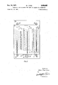
- FIG. 2 shows in a diagrammatic front elevation the movable scale.
- FIG. 1 shows a telemetering apparatus in conjunction with the tanks C C and C of a tanker N.
- the measuring system for the tank C only has been show in detail.
- insufilation tubes a, b, c, d which discharge compressed gas into the tank at various levels from the top to the bottom.
- the four insufilation tubes are supplied with gas from a pressurized source S through a common safety valve 10 and built-in flow chamber micro-regulators m m m mg.
- the purpose of the micro-regulators is to maintain the rate of insufilation constant whatever the pressure of the gas in the source S and the level of liquid in the tank C
- Each micro-regulator incorporates a pressure-sensing chamber which is merely a tank connected in series with the gas line and which is sufficiently large for the pressure in the chamber to be constant and to be independent of the disturbances in the tank due to the introduction of the gas through the tubes a, b, c and d.
- Three manometer tubes t t and t are situated in the control room of the ship opposite three series E E and E of curves which are etched on a movable scale A which will be described in detail hereinafter.
- the tube 2 is connected between the pressure-sensing chambers of the micro-regulators m and mg by two lines 1 and I
- the t is connected between the pressure-sensing chambers of the micro-regulators m and m by two lines l and I
- the tube t is connected between the pressure-sensing chambers of the micro-regulators m and m by two lines 1,, and l
- Each of the lines l l 1 and I contains a safety valve 0,, c 0 and c respectively which automatically close if the gas supply fails in order to prevent vapours from the tanks reaching the control room.
- a hydrometer D is connected across the lines l and l and its operation is controlled by apressure-responsive switch M which is connected across the lines and l
- the manometer tube t gives a measurement of the pressure difference between the bottom and the top of the tank C this is an overall coarse measurement of the liquid level in the tank.
- the tube t measures the pressure difference between a point a short distance below the maximum liquid level of the tank and the top of the tank; this gives a fine measurement of the liquid if it is near the top of the tank.
- the tube t detects the pressure difference between the bottom of the tank and a point situated a little above the bottom; this gives a fine measurement of the liquid level when draining is almost complete.
- the scale A includes three series of graduated curves E E B
- the tank is one which has a maximum liquid level of 16 metres from the bottom.
- the curves E range from 14.9 to 16.5 m., the curves E from 0 to 17 m., and curves E from 0 to 1.7 m.
- the translucent scale A is arranged to be moved horizontally over the front of the manometer tubes t t and 1 by means of rollers g.
- the scale A carries a rack 21 which is arranged to co-operate with a pinion 22 rotatably mounted on the backing 20 which carries the tubes t t and t and the rollers g.
- the pinion can be controlled by a knurled knob 23. By means of this knob 23 it is possible to control the relative horizontal displacement of the scale A and the backing 20.
- the scale A also carries a relative density scale e and the backing carries a pointer i so that any position of the scale A in relation to the backing 20 corresponds to a certain relative density as shown on scale e.
- the apparatus is used as follows: when the tank C has been filled to a level which is near the maximum level, the manometer tubes t and t indicate two values for the liquid level on the curves E and E The scale A is then moved relative to the backing 20 until these values are equal (in the example shown, 15.65 m.) With the scale in this position the pointer i indicates a certain value for the density on the scale 2 (in this case 0.81). Thus it is possible to obtain an indication of the level of liquid in the tank and the density of the liquid at the same time.
- the manometers t and t are used when the level is near the bottom of the tank.
- the provision of the hydrometer D is just a safety measure.
- Apparatus for measuring the level of liquid in a reservoir including at least two manometer tubes arranged to detect the pressure difference between at least two different pairs of levels in the reservoir, a scale movable in relation to the tubes and carrying at least two series of curves, each associated with a manometer tube, each curve in a series representing a range of heights of liquid in the manometer tube for a given level of liquid in the reservoir and for a range of densities of liquid in the reservoir.
- each manometer tube is connected to two insufllation tubes.
- one of the manometer tubes has one of its probes situated at the top of the reservoir and the other situated a small distance below the first insufilation tube.
- Apparatus as claimed in claim 2 in which one manometer tube has one probe situated at the bottom of the reservoir and the other a small distance above the first tube.
- Apparatus as claimed in claim 2 in which one manometer tube has one probe, situated at the top of the reservoir and the other probe situated at the bottom of the reservoir.
- the scale also carries density markings arranged so that when movement of the scale has equalized the readings of the level of liquid in two of the manometer tubes, the density of the liquid in the reservoir is indicated by a particular marking.
- connection between each manometer tube and its insuffiation tube or tubes contains a micro-regulator for maintaining the flow of gas through the insufflation tube constant Whatever the level of the liquid in the reservoir.
- connection also contains a safety valve which is arranged to close if the flow of gas fails.
- Apparatus as claimed in claim 1 in combination with a reservoir, and including means within said reservoir for transmitting pressures representative of said two different pairs of levels in the reservoir to said manometer tubes.
Landscapes
- Physics & Mathematics (AREA)
- Fluid Mechanics (AREA)
- General Physics & Mathematics (AREA)
- Measuring Fluid Pressure (AREA)
- Measurement Of Levels Of Liquids Or Fluent Solid Materials (AREA)
- Level Indicators Using A Float (AREA)
Applications Claiming Priority (1)
| Application Number | Priority Date | Filing Date | Title |
|---|---|---|---|
| FR6909078A FR2038714A5 (sv) | 1969-03-27 | 1969-03-27 |
Publications (1)
| Publication Number | Publication Date |
|---|---|
| US3620085A true US3620085A (en) | 1971-11-16 |
Family
ID=9031361
Family Applications (1)
| Application Number | Title | Priority Date | Filing Date |
|---|---|---|---|
| US866700A Expired - Lifetime US3620085A (en) | 1969-03-27 | 1969-10-15 | Apparatus for measuring the level of liquid in a reservoir |
Country Status (6)
| Country | Link |
|---|---|
| US (1) | US3620085A (sv) |
| JP (1) | JPS4936266B1 (sv) |
| DE (1) | DE2014765C3 (sv) |
| ES (1) | ES373223A1 (sv) |
| FR (1) | FR2038714A5 (sv) |
| GB (1) | GB1271695A (sv) |
Cited By (14)
| Publication number | Priority date | Publication date | Assignee | Title |
|---|---|---|---|---|
| US3969941A (en) * | 1973-11-08 | 1976-07-20 | E. Rapp Electronik Gmbh | Level detector for liquids and other flowable masses |
| US3969942A (en) * | 1975-08-11 | 1976-07-20 | Hope Henry F | Liquid level responsive apparatus |
| US3985027A (en) * | 1975-07-10 | 1976-10-12 | Sperry-Sun, Inc. | Controlled flow impedance in a pressure sensing system |
| US4006635A (en) * | 1973-11-08 | 1977-02-08 | Cermat | Liquid level measuring process and indicator |
| DE2827428A1 (de) * | 1978-06-22 | 1980-01-10 | Axel Ramus | Verfahren und vorrichtung zur feststellung einer fluessigkeits- oder gasphase in fluessigkeitfuehrenden systemen |
| EP0022739B1 (fr) * | 1979-07-16 | 1982-03-17 | Arbed S.A. | Procédé et dispositif pour la mesure du niveau de la scorie dans un récipient métallurgique et pour l'appréciation de son état physique |
| EP0048589A1 (en) * | 1980-09-19 | 1982-03-31 | Tankmaster Limited | Tank contents gauge |
| US4665746A (en) * | 1985-07-17 | 1987-05-19 | Sheppard William J | Liquid level measuring apparatus and method |
| US5020368A (en) * | 1988-11-30 | 1991-06-04 | Shell Oil Company | Method and system measuring a vertical density profile of a fluid |
| US5163324A (en) * | 1992-02-24 | 1992-11-17 | General Motors Corporation | Bubbler liquid level sensing system |
| US5406828A (en) * | 1993-11-16 | 1995-04-18 | Yellowstone Environmental Science, Inc. | Method and apparatus for pressure and level transmission and sensing |
| US5423226A (en) * | 1993-11-16 | 1995-06-13 | Yellowstone Environmental Science, Inc. | Flow measurement system |
| WO1997008517A1 (en) * | 1995-08-23 | 1997-03-06 | Kockum Sonics Ab | Method and device for measuring liquid levels |
| US20100242594A1 (en) * | 2007-09-27 | 2010-09-30 | Yasuhiro Onishi | Bubble column type hydrocarbon synthesis reactor, and slurry level detecting method |
Families Citing this family (1)
| Publication number | Priority date | Publication date | Assignee | Title |
|---|---|---|---|---|
| EP0145379A3 (en) * | 1983-11-23 | 1987-06-24 | Transitron Electronics Corp. | Tank level measuring system |
-
1969
- 1969-03-27 FR FR6909078A patent/FR2038714A5/fr not_active Expired
- 1969-06-14 JP JP44046756A patent/JPS4936266B1/ja active Pending
- 1969-06-30 GB GB32836/69A patent/GB1271695A/en not_active Expired
- 1969-10-15 US US866700A patent/US3620085A/en not_active Expired - Lifetime
- 1969-10-17 ES ES373223A patent/ES373223A1/es not_active Expired
-
1970
- 1970-03-26 DE DE2014765A patent/DE2014765C3/de not_active Expired
Cited By (15)
| Publication number | Priority date | Publication date | Assignee | Title |
|---|---|---|---|---|
| US3969941A (en) * | 1973-11-08 | 1976-07-20 | E. Rapp Electronik Gmbh | Level detector for liquids and other flowable masses |
| US4006635A (en) * | 1973-11-08 | 1977-02-08 | Cermat | Liquid level measuring process and indicator |
| US3985027A (en) * | 1975-07-10 | 1976-10-12 | Sperry-Sun, Inc. | Controlled flow impedance in a pressure sensing system |
| US3969942A (en) * | 1975-08-11 | 1976-07-20 | Hope Henry F | Liquid level responsive apparatus |
| DE2827428A1 (de) * | 1978-06-22 | 1980-01-10 | Axel Ramus | Verfahren und vorrichtung zur feststellung einer fluessigkeits- oder gasphase in fluessigkeitfuehrenden systemen |
| EP0022739B1 (fr) * | 1979-07-16 | 1982-03-17 | Arbed S.A. | Procédé et dispositif pour la mesure du niveau de la scorie dans un récipient métallurgique et pour l'appréciation de son état physique |
| EP0048589A1 (en) * | 1980-09-19 | 1982-03-31 | Tankmaster Limited | Tank contents gauge |
| US4665746A (en) * | 1985-07-17 | 1987-05-19 | Sheppard William J | Liquid level measuring apparatus and method |
| US5020368A (en) * | 1988-11-30 | 1991-06-04 | Shell Oil Company | Method and system measuring a vertical density profile of a fluid |
| US5163324A (en) * | 1992-02-24 | 1992-11-17 | General Motors Corporation | Bubbler liquid level sensing system |
| US5406828A (en) * | 1993-11-16 | 1995-04-18 | Yellowstone Environmental Science, Inc. | Method and apparatus for pressure and level transmission and sensing |
| US5423226A (en) * | 1993-11-16 | 1995-06-13 | Yellowstone Environmental Science, Inc. | Flow measurement system |
| WO1997008517A1 (en) * | 1995-08-23 | 1997-03-06 | Kockum Sonics Ab | Method and device for measuring liquid levels |
| US20100242594A1 (en) * | 2007-09-27 | 2010-09-30 | Yasuhiro Onishi | Bubble column type hydrocarbon synthesis reactor, and slurry level detecting method |
| US8479572B2 (en) | 2007-09-27 | 2013-07-09 | Nippon Steel Engineering Co. Ltd. | Bubble column type hydrocarbon synthesis reactor, and slurry level detecting method |
Also Published As
| Publication number | Publication date |
|---|---|
| DE2014765A1 (de) | 1970-10-01 |
| ES373223A1 (es) | 1972-05-16 |
| JPS4936266B1 (sv) | 1974-09-28 |
| DE2014765B2 (de) | 1978-10-12 |
| DE2014765C3 (de) | 1979-06-13 |
| GB1271695A (en) | 1972-04-26 |
| FR2038714A5 (sv) | 1971-01-08 |
Similar Documents
| Publication | Publication Date | Title |
|---|---|---|
| US3620085A (en) | Apparatus for measuring the level of liquid in a reservoir | |
| US4669309A (en) | Tank contents gauge | |
| US4006635A (en) | Liquid level measuring process and indicator | |
| US3744306A (en) | Method and apparatus for measuring the ullage of a vessel | |
| US3371534A (en) | Level sensing apparatus | |
| US2866339A (en) | Thermally compensating vapor pressure measurement system | |
| US3572121A (en) | Device for pneumatically measuring liquid levels | |
| US2342696A (en) | Liquid level gauge | |
| US2691223A (en) | Liquid level gauge | |
| US2791906A (en) | Boiler water gauges providing uncorrected level indications and level indications corrected for density of the boiler water | |
| US1699812A (en) | Riquid-level-indicating system | |
| US1457406A (en) | Depth and specific-gravity measuring apparatus | |
| US3262305A (en) | Method and apparatus for calibrating differential pressure cells | |
| US1131412A (en) | Pneumatic depth-indicator. | |
| US2991645A (en) | Mobile calibration unit for liquid meters | |
| US2353275A (en) | Container pressure withstanding testing device | |
| US1894366A (en) | Pressure gauge automatically correcting the temperature | |
| US2898763A (en) | Specific gravity indicators | |
| US4091669A (en) | Pressure responsive apparatus | |
| US2674128A (en) | Liquid level gauge | |
| US3376732A (en) | Manometer | |
| US2342587A (en) | Method of and means for indicating pressures | |
| GB782691A (en) | Differential pneumatic linear dimension comparator gauge | |
| US2312787A (en) | System of gauging pressures | |
| US3431078A (en) | Respiration measuring apparatus |