US3616754A - Method and apparatus for selectively preventing the explosion of explodable projectiles - Google Patents
Method and apparatus for selectively preventing the explosion of explodable projectiles Download PDFInfo
- Publication number
- US3616754A US3616754A US659688A US3616754DA US3616754A US 3616754 A US3616754 A US 3616754A US 659688 A US659688 A US 659688A US 3616754D A US3616754D A US 3616754DA US 3616754 A US3616754 A US 3616754A
- Authority
- US
- United States
- Prior art keywords
- signal
- location
- projectile
- predetermined
- range
- Prior art date
- Legal status (The legal status is an assumption and is not a legal conclusion. Google has not performed a legal analysis and makes no representation as to the accuracy of the status listed.)
- Expired - Lifetime
Links
Images

Classifications
-
- F—MECHANICAL ENGINEERING; LIGHTING; HEATING; WEAPONS; BLASTING
- F42—AMMUNITION; BLASTING
- F42C—AMMUNITION FUZES; ARMING OR SAFETY MEANS THEREFOR
- F42C15/00—Arming-means in fuzes; Safety means for preventing premature detonation of fuzes or charges
- F42C15/40—Arming-means in fuzes; Safety means for preventing premature detonation of fuzes or charges wherein the safety or arming action is effected electrically
-
- F—MECHANICAL ENGINEERING; LIGHTING; HEATING; WEAPONS; BLASTING
- F42—AMMUNITION; BLASTING
- F42C—AMMUNITION FUZES; ARMING OR SAFETY MEANS THEREFOR
- F42C13/00—Proximity fuzes; Fuzes for remote detonation
- F42C13/04—Proximity fuzes; Fuzes for remote detonation operated by radio waves
Definitions
- This invention relates to a method and apparatus for selectively preventing the explosion of explodable projectiles.
- the supporting fire power itself may not be sufiiciently accurate to prevent injury to friendly troops and positions. It must be noted that if a number of artillery rounds, even where the latter are of the same caliber and from the same lot, are fired from the same weapon with the same settings in quadrant, elevation and deflection, the rounds will not all fall at a single point but will be scattered. The points of impact of the projectiles fired in the above manner will be scattered both laterally and transversely. Dispersion, as this phenomena is called, is caused by inherent errors, not by mistakes or constant errors. Dispersion is the result of minor variations of many elements from round to round, for example, conditions in the bore, conditions in the carriage, and conditions during flight. Thus, even where it is possible to accurately aim projectiles from afar at an enemy engaged in close combat with friendly troops, the risks are great that many of the rounds fired will fall amongst the friend- 1y troops.
- an object of the present invention to permit the use of artillery and/or air support in assisting friendly troops engaged in close combat with the enemy while eliminating, or at least substantially reducing, the aforesaid risks of injury to the friendly troops which would otherwise result from such supporting fire power.
- Still another object of the present invention is to provide a method as stated above which may be used with proximity fused projectiles or otherwise controlled projectiles as well as with those which explode upon impact.
- a concomitant object of the present invention is to permit friendly projectiles to explode as close to friendly ice positions as possible yet not so close as to result in substantial injury to such friendly positions.
- a wireless signal of predetermined characteristics is transmitted from a location to be protected, for example, from a position held by friendly troops and which is surrounded by enemy troops at a close range
- Friendly projectiles incorporating a signal detecting device as hereinafter described may then be purposely propelled toward the general region containing such a location so as to explode as close as possible to such location yet far enough away to not cause substantial injury to the friendly troops there.
- the transmitter, carried by the friendly troops may be energized, at will, to transmit a signal defining, in space, a safety zone, for example, an umbrella shaped zone, at the boundary of which the transmitted signal has predetermined signal strength characteristics.
- the projectiles are equipped with receiving means capable of detecting a predetermined signal having such predetermined strength characteristics and to automatically prevent explosion of the respective projectile when a signal of such characteristics is detected.
- receiving means capable of detecting a predetermined signal having such predetermined strength characteristics and to automatically prevent explosion of the respective projectile when a signal of such characteristics is detected.
- friendly artillery and/or air fire power By aiming friendly artillery and/or air fire power at the enemy troops closest to the friendly position, or even at the perimeter of the friendly position itself, where friendly and enemy troops are engaged in close combat, a substantial number of rounds can be made to fall into and destroy the closely adjacent enemy troop position while those of the rounds which happen to fall into the safety zone of the friendly troops, as defined by the signal strength of the wireless signal transmitted by the friendly troops, would be automatically disarmed or otherwise placed in non-explosive condition so as to prevent injury to the friendly troops.
- the predetermined signal strength and thus the size of the safety zone is chosen of such magnitude, with respect to the explosive characteristics of the projectiles, that an explosion of such projectile just outside the safety zone would at least not substantially damage the location to be protected while the same explosion inside of said zone would at least slightly damage said location.
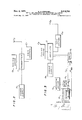
- FIG. 1 illustrates schematically the signal transmitter and its transmitted signals in relation to approaching projectiles equipped, in accordance with the present invention, with signal receiving and explosion preventing means;
- FIG. 2 shows diagrammatically a signal generating means according to the present invention
- FIG. 3 shows diagrammatically a receiver on, and the explosion preventing means of, a projectile which may be used together with the signal generating means of FIG. 2 in the manner illustrated in FIG. 1.
- a transmitter T located at L, continuously transmits a wireless signal S which forms, in space, when location L is on the ground as shown, a hemispherical zone Z about the transmitter T.
- a signal S displays a predetermined signal intensity 8; which is inversely proportional to the square of the distance Ra.
- a signal S of predetermined intensity 8 At the imaginary surface of hemisphere, i.e., at a radius greater than Ra the intensity of the signal S is, of course, lower than intensity S in accordance with the inverse square law.
- Transmitter T may be stationary or moving. It may be carried by military personnel, or it may be mounted on a moving vehicle, such as for example, a tank, a submarine or an aircraft. If mounted on a vehicle or carried by personnel, the location to be protected will obviously include such vehicle or such personnel and the hemispherical signal zone Z, i.e., the safety zone, will move with the transmitter T so as to always provide a signal umbrella about the location to be protected, namely, location L.
- location as used herein is intended to include moving and/or stationary objects, personnel and vehicles as well as portions of terrain, water and/ or space.
- artillery support fire P from distant artillery weapons A can, in accordance with the present invention, be used effectively against location B without risk of substantial injury to the friendly personnel at location L.
- each of the artillery rounds in the form of projectiles P I through P 6, propelled toward the general region of terrain G containing the zone Z, carries, as hereinafter described in greater detail, a receiver or detector means capable of detecting a predetermined signal of predetermined intensity S
- the projectiles P I through P 6, fired from artillery piece A toward the general region containing zone Z, will be dispersed in accordance with a known probability curve.
- Round F I has, in the position shown, not yet reached zone Z and is, therefore, still active but will be prevented from exploding, e.g., will be disarmed, as soon as it comes within range Ra of location L and detects the signal of signal intensity S as will be further explained hereinafter.
- Rounds P 3 through P 6 will never enter zone Z, i.e., will never come within range Ra of location L and will therefore explode either upon impact or in the air via a proximity fuse or similar detonating device. It will be understood, of course, that if transmitter T is mounted on a moving vehicle, the zone Z may shift position during flight of the projectiles so that others of the projectiles may come within range Ra of the moving transmitter and thus be disarmed.
- the disarming means may be such that if, after a projectile has been disarmed as described above, the zone Z is shifted by moving transmitter T to another location, leaving the projectile (which may have fallen harmlessly to the ground, or may still be in flight) beyond the then range Ra, the detonating circuit of the projectile will be activated once more and the projectile may then explode.
- a projectile P 7 in the form of an air to ground missile or bomb, fired at or dropped on the enemy position E from a friendly airplane and provided with receiver means, as herein described, may, in its flight, pass through a portion of zone Z as shown.
- the missile will be prevented from exploding by the wireless signal of signal strength at least equal to S; which it will be receiving. This Will be the 0356 even though the proximity fuse, timing fuse, or other fuse of missile P 7 shall have given the order to detonate. Under these circumstances, however, should the missile P 7 once more emerge from zone Z, as shown, explosion will occur since the detonating signal will still be in effect while the intensity of the wireless signal received by the missile will be less than the signal intensity 5; required to prevent detonation.
- the range Ra may be chosen of such magnitude that an explosion, having the given explosive characteristics, just outside the chosen range Ra would at least not substantially damage the location L, while an explosion of said given explosive characteristics inside of said range Ra would at least slightly damage location L.
- range Ra are not only the explosive power of the projectile but also the type of projectile e.g. anti-personnel, armor-piercing, etc. and the character of location L, e.g. whether the transmitter is carried by a foot soldier or on a tank. The latter are given as examples of the considerations which enter into a determination of the explosive characteristics of projectiles as that term is used herein.
- Enemy positions in close proximity to friendly troops can be wiped out with artillery or similar fire power from distant positions while shrouding the friendly troops in an umbrella-like safety zone within which all friendly projectiles, which would otherwise cause substantial injury to the friendly troops, are automatically disarmed or otherwise prevented from exploding.
- the projectiles may, for example, be of the type which are permanently armed and adapted to explode upon impact, or they may be of the type which are permanently armed and explode in response to action of a proximity fuse, or of the type which are normally disarmed and which become armed in response to a remote control signal or in response to a proximity fuse or similar device.
- close combat fighting it is, of course, desirable to explode rounds in the midst of enemy positions, as close to the friendly positions as possible, yet without risking substantial injury to such friendly positions.
- either the transmitter T at location L, or the receiver on the proectile, or both, may be adjusted to interrupt the detonatmg circuit and prevent explosion of the projectile, whenever such projectile comes within the range Ra of the transmitter.
- the signal intensity of the signal transmitted by transmitter T will be a fixed predetermined quantity which will remain substantially constant throughout.
- FIG. 2 shows, in diagrammatic form, a signal generating means according to the present invention.
- a power supply 8 supplies power at a given voltage level to a conventional transmitter T, for transmitting an amplitude modulated radio frequency signal.
- a conventional tuning means C in the form, for example, of a variable tuning condenser may be connected in a manner well known to those skilled in the art to transmitter T so that the latter will generate a predetermined signal, for example, a signal of predetermined frequency, to be radiated by the antenna
- a gain control G in the form, for example, of a variable potentiometer connected to an amplifier stage of transmitter T in a manner well known to those skilled in the art.
- FIG. 3 illustrates schematically a projectile P carrying, according to the present invention, a detector or receiver means for receiving the signal transmitted by said signal generating means.
- the projectile carries, according to one embodiment of the invention, a power supply S for supplying an amplitude modulation receiver R with voltage at a predetermined level.
- the receiver R is adapted to receive the energy radiated by the antenna A of transmitter T.
- Conventional tuning means C which may be in the form of variable tuning condensers is connected to the receiver R for tuning the latter to a predetermined frequency identical to the predetermined frequency of the signal S transmitted by transmitter T.
- An adjustment means in the form of a conventional gain control G is connected in a well known manner to one of the amplifier stages of receiver R.
- the adjustment means or gain control G may be in the form of a variable potentiometer and permits selection of an amplifieroutput of predetermined voltage level when a signal with the aforesaid predetermined frequency and having a signal intensity S is received at antenna A
- a signal intensity sensing means which may be in the form of relay R having normally closed relay contacts '1 and 2, is connected to the output of said receiver amplifier.
- the aforesaid predetermined voltage level of the amplifier output is chosen such that sufficient power is available to actuate relay R to open the normally closed relay contacts 1, 2 thereof when a signal S having said predetermined signal intensity 5; is received at antenna A,.
- the gain control G of the particular projectile would have to be adjusted in a direction to increase the gain of the amplifier.
- the required voltage level for actuating relay R to open the normally closed contacts thereof will be achieved when a signal of lower signal intensity than previously is received at antenna A whereby the range Ra at which explosion will be prevented, is effectively increased.
- the signal generating means and the signal detecting means may be of any desired degree of complexity so as to prevent enemy countermeasures from interfering with the response of the receiver to the transmitted signal.
- Receiver R may be of the type comprising a radio frequency amplifier, a detector for developing an audio frequency signal representing the modulation envelope, an amplifier stage, and a detector for developing a DC. signal representing the amplitude of the audio frequency signal used to energize relay R
- the receiver and transmitter herein may be generally similar to the receiver and corresponding transmitter described and illustrated in US. Pat. 2,788,521.
- transmitter T may be substantially identical to the transmitter designated by 1 in the latter patent.
- Tuning means C herein may be in the form of a condenser such as condenser C of the patent, while the power supply 8, may be in the form shown in the patent, i.e., as including a battery B a vibrator V and a transformer T.
- the manner of connecting a gain control G, to the circuit illustrated by the patent will be obvious to those skilled in the art and therefore requires no further explanation.
- the receiver R herein may be of a construction similar to that shown in FIG. 2 of the patent where relay R is the counterpart to my relay R except that my normally closed contacts 1, 2 would be substituted for contacts a thereof.
- the variable capacitor C10 shown in the patent is the counterpart of my tuning means C Gain control G may, of course, be suitably connected to the circuit shown in FIG. 2 of the patent in a manner which will be obvious to those skilled in the art so as to permit varying of the gain thereof for the reasons already described.
- the value of resistor R14 of capacitor C14, of the patent may be chosen to provide any desired time lag before response of the relay R,, or, if desired, the latter time delay circuit may be eliminated entirely for purposes of the present invention.
- Each of the projectiles P 1-7 comprises an explosive charge E a detonator D for exploding said charge, a detonating device D and a disarming means in the form of disarming and detonating circuit C
- the detonating device D may be of any well known construction, such as for example, a proximity fuse which is connected in circuit with a relay R so as to energize the latter when the projectile comes within a predetermined distance of its target.
- Normally open contacts 3, 4 of relay R are located in circuit C in series with the detonator D, a battery B and the normally closed contacts 1, 2 of relay R
- the latter relay is in circuit with receiver R and is arranged to be energized by receiver R when a predetermined signal of intensity S is detected at antenna A,.
- normally open contacts 3, 4 of relay R are in series with the normally closed contacts 1, 2 of relay R Under normal conditions, therefore, i.e. when the projectile is outside of zone Z, normally closed contacts 1, 2 of relay R remain closed so that when the detonating device D responds to a predetermined proximity to the target, relay R is activated thereby closing the contacts 3, 4 thereof to energize the detonator D which results in explosion of the explosive charge.
- an explodable projectile is permitted to explode in the normal manner whenever the latter is beyond a predetermined range Ra at the time of impact or at the time it receives the command to explode from its Proximity fuse or similar means, but is prevented from exploding whenever it passes Within the range Ra of the location L which it is desired to protect.
- the arrangement according to one form of the present invention is such that the required voltage level at the output of the amplifier stage of receiver R, for actuating relay R is reached only in response to receipt at antenna A of a signal of said predetermined frequency and having said predetermined signal strength S Knowing the explosive characteristics of the projectile, i.e. the range from the point of explosion at which various degrees of destruction will take place, a safe range Ra may be determined for the location L. Knowing the signal intensity of the signal transmitted by transmitter T, the signal intensity 8; of such signal at range Ra from said location L can be readily determined.
- gain control G of receiver R, carried by the projectiles P can be preset to provide a receiver output having a voltage level suflicient for actuating relay R when a signal having the predetermined signal intensity S is detected by antenna A
- receiver R since the frequency of transmitter T is known, receiver R may be tuned to the same frequency so that the latter will respond only to a signal at said frequency.
- both the preselected frequency as well as the gain control value of G are preset in each projectile before firing or release thereof.
- the frequency characteristics of the transmitted signal may be varied from time to time to prevent the enemy from interfering with the above described procedure. Naturally, each time the transmitted signal frequency characteristics are varied the receiver R must be tuned accordingly to the new frequency.
- friendly troops should, for some reason, find the friendly projectiles exploding too close to the friendly positions they can readily vary the gain control G, of transmitter T so as to increase the signal intensity of the transmitted signal to thereby disarm the projectiles at a range which is greater than the range Ra previously described.
- the signals received by the antenna A are detected by the detector of receiver R and amplified by an amplifier stage of the receiver R, and the output of the amplifier is fed to relay R
- the output voltage level will be such as to actuate relay R to open the detonator circuit C and to thereby prevent the projectile from exploding.
- the transmitter apparatus carried by the friendly troops may be provided with a secondary receiver for receiving the radio signal transmitted by the proximity fuze and in response thereto (transponder) actuating the signal generating device of the present invention.
- the latter transmitter will be energized only when the projectile fuze signal is received.
- Suitable transponder means for accomplishing such actuation are well known in the art and form no part of the present invention.
- wireless signal is intended to include any signal or signals capable of being transmitted without the use of wires.
- location as used herein is intended to include a moving location as well as a stationary one depending on whether signal generating means T is moving or stationary.
- the range from said location at which said one predetermined signal intensity is present is such that an explosion of said given explosive characteristics just outside said chosen range would at least not substantially damage said location while an explosion of said given explosive characteristics inside of said range would at least slightly damage said location.
- a method according to claim 1 comprising controlling the power at which said signal is transmitted so as to provide a signal of said predetermined signal strength at the chosen range from said location.
- a method according to claim 1, comprising controlling the signal detecting means of said projectile in dependence on the explosive characteristics of said projectile.
- Apparatus for selectively preventing the explosion of explodable projectiles of given explosive characteristics in proximity to a given location comprising:
- receiver means positioned on said projectile for receivmg said wireless signal
- d1sarm1ng means on said projectile operatively connected to said detector means for automatically disarming said projectile in response to detection by said detector means that said projectile is within said given range of said given location, said given range being chosen, with respect to said given explosive characteristics of said projectile, such that an exploslon having said given explosive characteristics just outslde said chosen range would at least not substantially damage said location while an explosion having said given explosive characteristics within said range would at least slightly damage said location.
- said detector means on said projectile being adapted to detect said predetermined signal having said predetermined intensity
- said signal generator means comprising a portable transmitter for transmitting a wireless signal of predetermined characteristics while moving along a given path.
- said signal generating means comprises means for controlling the intensity of the signal generated thereby so that said signal will display said predetermined signal intensity at said chosen range from said location.
- Apparatus according to claim 5 further comprising adjustment means operatively connected to said detector means on said projectile for adjusting said detector means to respond to one of a plurality of different given signal intensities, said signal generated by said signal generating means displaying a different signal intensity at different distances from said location and said detector being adjustable to respond to a chosen one of said signal intensities, whereby said predetermined range can be chosen in correspondence to' the particular explosive characteristics of said projectile.
- said signal generating means comprises transmitter means for transmitting a radio signal.
- said transmitter means comprising tuning means for providing for transmission a signal having given frequency characteristics.
- said detector means comprises radio receiver means including adjustable tuner means whereby said detector means will respond only to said signal of given frequency characteristics.
- said detector means comprising signal intensity sensing means actuated only by a signal having said predetermined intensity characteristics so that in order to prevent explosion of said projectile coming within said predetermined range of said location, said predetermined signal of said predetermined intensity must be present at said predetermined range.
- Apparatus according to claim 4 further comprising control means associated with said signal generator means for varying said signal characteristics of said transmitted signal so as to permit adjustment at said location of said given range.
- an explodable projectile of given explosive characteristics and having a detonator a detonator circuit including a normally closed relay, a radio receiver having an output circuit adapted to open said normally closed relay, said radio receiver actuating said relay only in response to receipt of a signal having a predetermined intensity; and a transmitter located at a location to be protected, said transmitter having means to radiate a signal displaying said predetermined intensity at a predetermined range from said location but not beyond said range, whereby when said transmitter is operated and said projectile approaches the location of said transmitter said radio receiver actuates said relay when reaching the range from said location at which said predetermined signal displays said predetermined intensity characteristics, thereby rendering said detonating circuit inoperative, whereas when said projectile does not come Within said predetermined range of said location said receiver will not receive said signal having said predetermined intensity characteristics and said relay will remain closed to render said detonating circuit operative, said range being chosen with respect to the explosive power of said projectile to be of such a magnitude that the location at which said transmitter
- Apparatus according to claim 14 wherein said relay is arranged to return to its normally closed position so as to again render said detonating circuit operative in response to cessation of receipt of a signal of said predetermined signal intensity by said radio receiver in the event said projectile passes outside of said predetermined range after having been within said predetermined range.
- said given range being chosen, with respect to the given explosive characteristics of said projectile, such that an explosion of said given explosive characteristics just outside said chosen range would at least not substantially damage said location while an explosion of said given explosive characteristics inside of said range would at least slightly damage said location.
Abstract
PROVIDING ABOUT A LOCATION TO BE PROTECTED A WIRELESS SIGNAL HAVING A PREDETERMINED INTENSITY AT A GIVEN RANGE FROM SAID LOCATION, AND DETECTING SAID SIGNAL OF PREDETERMINED INTENSITY SO AS TO PREVENT EXPLOSION OF FRIENDLY
PROJECTILES IN THE EVENT THE LATTER COME WITHIN SAID GIVEN RANGE OF SAID LOCATION.
PROJECTILES IN THE EVENT THE LATTER COME WITHIN SAID GIVEN RANGE OF SAID LOCATION.
Description
M. A. FRENKEL 3,616,754 METHOD AND APPARATUS FOR SELECTIVELY PREVENTING Nov. 2, 1971 THE EXPLOSION OF EXPLODABLE PROJECTILES Filed Aug. 10, 1967 2 Sheets-Shoat 1 INVI'JN'IUIL MARVIN A FRENKEL HY%4M7 United States Patent US. (ll. 102-70.2 R 16 Claims ABSTRACT OF THE DISCLOSURE Providing about a location to be protected a wireless signal having a predetermined intensity at a given range from said location, and detecting said signal of predetermined intensity so as to prevent explosion of friendly projectiles in the event the latter come within said given range of said location.
This invention relates to a method and apparatus for selectively preventing the explosion of explodable projectiles.
In many combat situations, for example during close infantry combat, in jungle warfare, or when visibility is bad, present means do not permit artillery and/or air support because of the fear of injury to the closely adjacent friendly troops. A convoy ambushed while moving along a winding road, for example, may not be able to sufficiently accurately provide positional information for artillery and/or air support to itself escape risk of injury resulting from such supporting fire power.
Furthermore, the supporting fire power itself may not be sufiiciently accurate to prevent injury to friendly troops and positions. It must be noted that if a number of artillery rounds, even where the latter are of the same caliber and from the same lot, are fired from the same weapon with the same settings in quadrant, elevation and deflection, the rounds will not all fall at a single point but will be scattered. The points of impact of the projectiles fired in the above manner will be scattered both laterally and transversely. Dispersion, as this phenomena is called, is caused by inherent errors, not by mistakes or constant errors. Dispersion is the result of minor variations of many elements from round to round, for example, conditions in the bore, conditions in the carriage, and conditions during flight. Thus, even where it is possible to accurately aim projectiles from afar at an enemy engaged in close combat with friendly troops, the risks are great that many of the rounds fired will fall amongst the friend- 1y troops.
It is, therefore, an object of the present invention to permit the use of artillery and/or air support in assisting friendly troops engaged in close combat with the enemy while eliminating, or at least substantially reducing, the aforesaid risks of injury to the friendly troops which would otherwise result from such supporting fire power.
It is another object of the present invention to provide a method by which a region containing friendly troops, whether they be stationary or moving close to enemy positions, may be blanketed with friendly artillery and/or fire power without risk of substantial injury to the friendly troops.
It is a further object of the present invention to provide apparatus which will accomplish the above method.
Still another object of the present invention is to provide a method as stated above which may be used with proximity fused projectiles or otherwise controlled projectiles as well as with those which explode upon impact.
A concomitant object of the present invention is to permit friendly projectiles to explode as close to friendly ice positions as possible yet not so close as to result in substantial injury to such friendly positions.
Generally speaking, according to the present invention, a wireless signal of predetermined characteristics is transmitted from a location to be protected, for example, from a position held by friendly troops and which is surrounded by enemy troops at a close range, Friendly projectiles incorporating a signal detecting device as hereinafter described, may then be purposely propelled toward the general region containing such a location so as to explode as close as possible to such location yet far enough away to not cause substantial injury to the friendly troops there. The transmitter, carried by the friendly troops, may be energized, at will, to transmit a signal defining, in space, a safety zone, for example, an umbrella shaped zone, at the boundary of which the transmitted signal has predetermined signal strength characteristics. The projectiles are equipped with receiving means capable of detecting a predetermined signal having such predetermined strength characteristics and to automatically prevent explosion of the respective projectile when a signal of such characteristics is detected. Thus, those of the projectiles which enter the safety zone defined by the Wireless gnals of predetermined strength characteristics, respond to detection of such signals by automatically becoming disarmed or otherwise, being placed in non-explosive condition.
By aiming friendly artillery and/or air fire power at the enemy troops closest to the friendly position, or even at the perimeter of the friendly position itself, where friendly and enemy troops are engaged in close combat, a substantial number of rounds can be made to fall into and destroy the closely adjacent enemy troop position while those of the rounds which happen to fall into the safety zone of the friendly troops, as defined by the signal strength of the wireless signal transmitted by the friendly troops, would be automatically disarmed or otherwise placed in non-explosive condition so as to prevent injury to the friendly troops. The predetermined signal strength and thus the size of the safety zone is chosen of such magnitude, with respect to the explosive characteristics of the projectiles, that an explosion of such projectile just outside the safety zone would at least not substantially damage the location to be protected while the same explosion inside of said zone would at least slightly damage said location.
The foregoing and other objects, characteristics and advantages of the method and apparatus according to the present invention will be more clearly understood from the following detailed description thereof when read in conjunction with the accompanying drawings, wherein:
FIG. 1 illustrates schematically the signal transmitter and its transmitted signals in relation to approaching projectiles equipped, in accordance with the present invention, with signal receiving and explosion preventing means;
FIG. 2 shows diagrammatically a signal generating means according to the present invention; and
FIG. 3 shows diagrammatically a receiver on, and the explosion preventing means of, a projectile which may be used together with the signal generating means of FIG. 2 in the manner illustrated in FIG. 1.
Referring now to the drawings and more particularly to FIG. 1 there is shown a terrain G including a location L, which it is desired to protect. In operation, a transmitter T, located at L, continuously transmits a wireless signal S which forms, in space, when location L is on the ground as shown, a hemispherical zone Z about the transmitter T. At the boundary of zone Z, i.e., at a radius Ra from the transmitter antenna A signal S displays a predetermined signal intensity 8; which is inversely proportional to the square of the distance Ra. Thus, at the imaginary surface of hemispherical zone Z there exists a signal S of predetermined intensity 8;. Beyond the imaginary surface of the hemisphere, i.e., at a radius greater than Ra the intensity of the signal S is, of course, lower than intensity S in accordance with the inverse square law.
Transmitter T may be stationary or moving. It may be carried by military personnel, or it may be mounted on a moving vehicle, such as for example, a tank, a submarine or an aircraft. If mounted on a vehicle or carried by personnel, the location to be protected will obviously include such vehicle or such personnel and the hemispherical signal zone Z, i.e., the safety zone, will move with the transmitter T so as to always provide a signal umbrella about the location to be protected, namely, location L. Thus, the term location as used herein is intended to include moving and/or stationary objects, personnel and vehicles as well as portions of terrain, water and/ or space.
Should the transmitter T be carried on a friendly truck ambushed by enemy forces, or carried by friendly personnel engaged in close combat with, or surrounded by enemy forces E, artillery support fire P from distant artillery weapons A can, in accordance with the present invention, be used effectively against location B without risk of substantial injury to the friendly personnel at location L. In accordance with the present invention, each of the artillery rounds, in the form of projectiles P I through P 6, propelled toward the general region of terrain G containing the zone Z, carries, as hereinafter described in greater detail, a receiver or detector means capable of detecting a predetermined signal of predetermined intensity S The projectiles P I through P 6, fired from artillery piece A toward the general region containing zone Z, will be dispersed in accordance with a known probability curve. Assuming that projectile P 4 follows the ideal trajectory for the settings of artillery piece A then the projected impacts of the remaining rounds will be distributed about location 1.; at, e.g., locations I I I I and I Some of the rounds, therefore, for example rounds P 1 and P 2, will enter the zone Z while rounds P 3, P 4, P S and P 6 have projected impacts outside of zone Z. As soon as round P Z enters zone Z it is prevented from exploding as a result of its detecting the signal of signal strength S Thus, upon passing within range Ra of location L, i.e., upon entering within the hemispherical safety zone defined by the signal intensity 8;, round P Z is prevented from exploding. Round F I has, in the position shown, not yet reached zone Z and is, therefore, still active but will be prevented from exploding, e.g., will be disarmed, as soon as it comes within range Ra of location L and detects the signal of signal intensity S as will be further explained hereinafter. Rounds P 3 through P 6 will never enter zone Z, i.e., will never come within range Ra of location L and will therefore explode either upon impact or in the air via a proximity fuse or similar detonating device. It will be understood, of course, that if transmitter T is mounted on a moving vehicle, the zone Z may shift position during flight of the projectiles so that others of the projectiles may come within range Ra of the moving transmitter and thus be disarmed. It will also be understood that the disarming means may be such that if, after a projectile has been disarmed as described above, the zone Z is shifted by moving transmitter T to another location, leaving the projectile (which may have fallen harmlessly to the ground, or may still be in flight) beyond the then range Ra, the detonating circuit of the projectile will be activated once more and the projectile may then explode. A projectile P 7 in the form of an air to ground missile or bomb, fired at or dropped on the enemy position E from a friendly airplane and provided with receiver means, as herein described, may, in its flight, pass through a portion of zone Z as shown. During the time missile P 7 is within the imaginary hemisphere defining zone Z, the missile will be prevented from exploding by the wireless signal of signal strength at least equal to S; which it will be receiving. This Will be the 0356 even though the proximity fuse, timing fuse, or other fuse of missile P 7 shall have given the order to detonate. Under these circumstances, however, should the missile P 7 once more emerge from zone Z, as shown, explosion will occur since the detonating signal will still be in effect while the intensity of the wireless signal received by the missile will be less than the signal intensity 5; required to prevent detonation.
Knowing the explosive characteristic of the projectiles P l through P 7, i.e., not only the explosive power but also the destructive power of the particular round under the particular conditions of use, namely the range from the detonating point at which substantial destruction results, the range Ra may be chosen of such magnitude that an explosion, having the given explosive characteristics, just outside the chosen range Ra would at least not substantially damage the location L, while an explosion of said given explosive characteristics inside of said range Ra would at least slightly damage location L. Taken into consideration in determining range Ra are not only the explosive power of the projectile but also the type of projectile e.g. anti-personnel, armor-piercing, etc. and the character of location L, e.g. whether the transmitter is carried by a foot soldier or on a tank. The latter are given as examples of the considerations which enter into a determination of the explosive characteristics of projectiles as that term is used herein.
Were projectiles P 1 and P 2 or missile P 7 to explode within range Ra, as shown, they would cause substantial damage to location L. The remaining projectiles being along their entire trajectories outside of range Ra, however, can be permitted to explode without risking substantial damage to location L. In this manner, it is possible to provide artillery, bomber or missile support to friendly troops even when the latter are engaged in close combat with enemy troops. It is possible to provide such support power at a proximity to the friendly troops not before possible without risk of substantial injury to friendly troops. Enemy positions in close proximity to friendly troops can be wiped out with artillery or similar fire power from distant positions while shrouding the friendly troops in an umbrella-like safety zone within which all friendly projectiles, which would otherwise cause substantial injury to the friendly troops, are automatically disarmed or otherwise prevented from exploding.
The projectiles may, for example, be of the type which are permanently armed and adapted to explode upon impact, or they may be of the type which are permanently armed and explode in response to action of a proximity fuse, or of the type which are normally disarmed and which become armed in response to a remote control signal or in response to a proximity fuse or similar device. In close combat fighting it is, of course, desirable to explode rounds in the midst of enemy positions, as close to the friendly positions as possible, yet without risking substantial injury to such friendly positions. This may be accomplished according to the present invention by locating the transmitter T at the friendly position and continuously transmitting a pre-determined signal therewith while blanketing the entire area with artillery rounds or pro ectiles, bombs and/or missiles equipped with explosion preventmg means such as described herein. The important thlng 1s to choose the range Ra to be of such a magnitude that for the particular explosive characteristics of the part cular projectiles used, explosion of such projectiles outside of range Ra will not cause substantial injury to the location L to be protected while explosion inside of range Ra would cause at least slight injury to such location. Once the range Ra is chosen for a projectile havmgpartrcular explosive characteristics then either the transmitter T at location L, or the receiver on the proectile, or both, may be adjusted to interrupt the detonatmg circuit and prevent explosion of the projectile, whenever such projectile comes within the range Ra of the transmitter.
Preferably, the signal intensity of the signal transmitted by transmitter T will be a fixed predetermined quantity which will remain substantially constant throughout. The only adjustments then will be adjustments of the receiver means on the individual projectiles so as to correspond to the explosive characteristics of the particular projectile, as described herein.
FIG. 2 shows, in diagrammatic form, a signal generating means according to the present invention. According to one embodiment of the present invention a power supply 8, supplies power at a given voltage level to a conventional transmitter T, for transmitting an amplitude modulated radio frequency signal. A conventional tuning means C in the form, for example, of a variable tuning condenser, may be connected in a manner well known to those skilled in the art to transmitter T so that the latter will generate a predetermined signal, for example, a signal of predetermined frequency, to be radiated by the antenna A For adjustment of the intensity of the signal transmitted there may be provided a gain control G in the form, for example, of a variable potentiometer connected to an amplifier stage of transmitter T in a manner well known to those skilled in the art.
FIG. 3 illustrates schematically a projectile P carrying, according to the present invention, a detector or receiver means for receiving the signal transmitted by said signal generating means. The projectile carries, according to one embodiment of the invention, a power supply S for supplying an amplitude modulation receiver R with voltage at a predetermined level. The receiver R is adapted to receive the energy radiated by the antenna A of transmitter T. Conventional tuning means C which may be in the form of variable tuning condensers is connected to the receiver R for tuning the latter to a predetermined frequency identical to the predetermined frequency of the signal S transmitted by transmitter T.
An adjustment means in the form of a conventional gain control G, is connected in a well known manner to one of the amplifier stages of receiver R. The adjustment means or gain control G may be in the form of a variable potentiometer and permits selection of an amplifieroutput of predetermined voltage level when a signal with the aforesaid predetermined frequency and having a signal intensity S is received at antenna A A signal intensity sensing means which may be in the form of relay R having normally closed relay contacts '1 and 2, is connected to the output of said receiver amplifier. The aforesaid predetermined voltage level of the amplifier output is chosen such that sufficient power is available to actuate relay R to open the normally closed relay contacts 1, 2 thereof when a signal S having said predetermined signal intensity 5; is received at antenna A,. Thus, if it is desired to increase the range Ra at which explosion of the projectile is prevented, for example, if it is decided to change to projectiles of different explosive characteristics, e.g., greater destructive capability, then, assuming a known and substantially constant transmitter signal intensity, the gain control G of the particular projectile would have to be adjusted in a direction to increase the gain of the amplifier. Thereby, the required voltage level for actuating relay R to open the normally closed contacts thereof will be achieved when a signal of lower signal intensity than previously is received at antenna A whereby the range Ra at which explosion will be prevented, is effectively increased.
The signal generating means and the signal detecting means may be of any desired degree of complexity so as to prevent enemy countermeasures from interfering with the response of the receiver to the transmitted signal.
Receiver R may be of the type comprising a radio frequency amplifier, a detector for developing an audio frequency signal representing the modulation envelope, an amplifier stage, and a detector for developing a DC. signal representing the amplitude of the audio frequency signal used to energize relay R The receiver and transmitter herein may be generally similar to the receiver and corresponding transmitter described and illustrated in US. Pat. 2,788,521.
For example, transmitter T may be substantially identical to the transmitter designated by 1 in the latter patent. Tuning means C herein may be in the form of a condenser such as condenser C of the patent, while the power supply 8, may be in the form shown in the patent, i.e., as including a battery B a vibrator V and a transformer T. The manner of connecting a gain control G, to the circuit illustrated by the patent will be obvious to those skilled in the art and therefore requires no further explanation.
The receiver R herein may be of a construction similar to that shown in FIG. 2 of the patent where relay R is the counterpart to my relay R except that my normally closed contacts 1, 2 would be substituted for contacts a thereof. The variable capacitor C10 shown in the patent is the counterpart of my tuning means C Gain control G may, of course, be suitably connected to the circuit shown in FIG. 2 of the patent in a manner which will be obvious to those skilled in the art so as to permit varying of the gain thereof for the reasons already described. It will further be obvious to those skilled in the art that the value of resistor R14 of capacitor C14, of the patent, may be chosen to provide any desired time lag before response of the relay R,, or, if desired, the latter time delay circuit may be eliminated entirely for purposes of the present invention.
Also, it will be obvious to those skilled in the art, and hence will require no further explanation here, that the holding-circuit of the patent including relay R,2 and switch SW may be eliminated for purposes of the present invention.
Each of the projectiles P 1-7 comprises an explosive charge E a detonator D for exploding said charge, a detonating device D and a disarming means in the form of disarming and detonating circuit C The detonating device D may be of any well known construction, such as for example, a proximity fuse which is connected in circuit with a relay R so as to energize the latter when the projectile comes within a predetermined distance of its target. Normally open contacts 3, 4 of relay R are located in circuit C in series with the detonator D, a battery B and the normally closed contacts 1, 2 of relay R The latter relay is in circuit with receiver R and is arranged to be energized by receiver R when a predetermined signal of intensity S is detected at antenna A,. Thus, the normally open contacts 3, 4 of relay R are in series with the normally closed contacts 1, 2 of relay R Under normal conditions, therefore, i.e. when the projectile is outside of zone Z, normally closed contacts 1, 2 of relay R remain closed so that when the detonating device D responds to a predetermined proximity to the target, relay R is activated thereby closing the contacts 3, 4 thereof to energize the detonator D which results in explosion of the explosive charge. E. If, however, prior to actuation of the detonating device D as described above, a predetermined signal of intensity S is detected by receiver R, the latter will actuate relay R to open the normally closed contacts 1, 2 thereof thus interrupting the circuit C and preventing energization of detonator D when, thereafter, the contacts 3, 4 of relay R are closed in response to actuation of the detonating device D Thus, when a signal of signal intensity S is received by receiver R, indicating that the projectile has entered the zone Z defined by the predetermined range Ra, the detonating ciricuit C is interrupted, and remains interrupted for as long as said signal of intensity 8; or greater is received, thereby preventing explosion of the projectile.
It is thus seen that according to the present invention an explodable projectile is permitted to explode in the normal manner whenever the latter is beyond a predetermined range Ra at the time of impact or at the time it receives the command to explode from its Proximity fuse or similar means, but is prevented from exploding whenever it passes Within the range Ra of the location L which it is desired to protect.
The arrangement according to one form of the present invention is such that the required voltage level at the output of the amplifier stage of receiver R, for actuating relay R is reached only in response to receipt at antenna A of a signal of said predetermined frequency and having said predetermined signal strength S Knowing the explosive characteristics of the projectile, i.e. the range from the point of explosion at which various degrees of destruction will take place, a safe range Ra may be determined for the location L. Knowing the signal intensity of the signal transmitted by transmitter T, the signal intensity 8; of such signal at range Ra from said location L can be readily determined. Once the signal intensity 8; at range Ra is known, gain control G, of receiver R, carried by the projectiles P can be preset to provide a receiver output having a voltage level suflicient for actuating relay R when a signal having the predetermined signal intensity S is detected by antenna A Similarly, since the frequency of transmitter T is known, receiver R may be tuned to the same frequency so that the latter will respond only to a signal at said frequency. Preferably, both the preselected frequency as well as the gain control value of G, are preset in each projectile before firing or release thereof. The frequency characteristics of the transmitted signal may be varied from time to time to prevent the enemy from interfering with the above described procedure. Naturally, each time the transmitted signal frequency characteristics are varied the receiver R must be tuned accordingly to the new frequency.
In the event friendly troops should, for some reason, find the friendly projectiles exploding too close to the friendly positions they can readily vary the gain control G, of transmitter T so as to increase the signal intensity of the transmitted signal to thereby disarm the projectiles at a range which is greater than the range Ra previously described.
In operation, the signals received by the antenna A, are detected by the detector of receiver R and amplified by an amplifier stage of the receiver R, and the output of the amplifier is fed to relay R When a signal of predetermined intensity is received at the selected frequency, the output voltage level will be such as to actuate relay R to open the detonator circuit C and to thereby prevent the projectile from exploding.
Where the friendly projectiles are equipped with fuzes which in normal operation themselves transmit a signal as, for example, radio proximity fuzes, then the transmitter apparatus carried by the friendly troops may be provided with a secondary receiver for receiving the radio signal transmitted by the proximity fuze and in response thereto (transponder) actuating the signal generating device of the present invention. Thus, rather than transmitting continuously, which might divulge to the enemy the position of the transmitter carried by the friendly troops, the latter transmitter will be energized only when the projectile fuze signal is received. Suitable transponder means for accomplishing such actuation are well known in the art and form no part of the present invention.
As used herein the term wireless signal is intended to include any signal or signals capable of being transmitted without the use of wires. The term location as used herein is intended to include a moving location as well as a stationary one depending on whether signal generating means T is moving or stationary.
While it will be apparent that the embodiments of the invention herein disclosed are calculated to fulfill the objects stated above it will be appreciated that the invention is susceptible to modification, variation and change without departing from the proper scope or fair meaning of the subjoined claims.
Having thus described my invention, what I claim and desire to protect by Letters Patent is:
1. In a method for selectively preventing the explosion of an explodable projectile of given explosive characteristics, the steps of:
providing said projectile with means capable of detecting a predetermined wireless signal of predetermined intensity;
transmitting said predetermined wireless signal from a location to be protected so as to form about said location, in space, a zone in which said signal displays predetermined consecutively lower signal intensities at corresponding predetermined consecutively greater ranges from said location;
propelling said explodable projectile toward the general region containing said zone; detecting, with said detecting means, said predetermined signal having a predetermined one of said predetermined signal intensities, when said projectile reaches the range from said location corresponding to said one predetermined signal intensity; and
automatically preventing explosion of said projectile in response to detection of said signal having said predetermined one of said signal intensities while permitting said projectile to explode in the event said projectile is not within said range corresponding to said one predetermined signal intensity signal;
said one predetermined signal intensity being chosen,
with respect to the given explosive characteristics of said projectile, such that the range from said location at which said one predetermined signal intensity is present is such that an explosion of said given explosive characteristics just outside said chosen range would at least not substantially damage said location while an explosion of said given explosive characteristics inside of said range would at least slightly damage said location.
2. A method according to claim 1 comprising controlling the power at which said signal is transmitted so as to provide a signal of said predetermined signal strength at the chosen range from said location.
3. A method according to claim 1, comprising controlling the signal detecting means of said projectile in dependence on the explosive characteristics of said projectile.
4. Apparatus for selectively preventing the explosion of explodable projectiles of given explosive characteristics in proximity to a given location, comprising:
signal generating means at said location for transmitting a wireless signal having predetermined signal characteristics;
receiver means positioned on said projectile for receivmg said wireless signal;
means cooperating with said receiver means for detecting from the characteristics of the signal received whether said projectile is or is not within a given range of said given location; and d1sarm1ng means on said projectile operatively connected to said detector means for automatically disarming said projectile in response to detection by said detector means that said projectile is within said given range of said given location, said given range being chosen, with respect to said given explosive characteristics of said projectile, such that an exploslon having said given explosive characteristics just outslde said chosen range would at least not substantially damage said location while an explosion having said given explosive characteristics within said range would at least slightly damage said location.
5. Apparatus according to claim 4 wherein said Wireless signal has a predetermined intensity at said given range from said location but not beyond said range:
said detector means on said projectile being adapted to detect said predetermined signal having said predetermined intensity;
and said disarming means on said projectile automatically disarming said projectile in response to detection of said predetermined signal of predetermined intensity.
6. Apparatus according to claim 5, said signal generator means comprising a portable transmitter for transmitting a wireless signal of predetermined characteristics while moving along a given path.
7. Apparatus according to claim wherein said signal generating means comprises means for controlling the intensity of the signal generated thereby so that said signal will display said predetermined signal intensity at said chosen range from said location.
8. Apparatus according to claim 5 further comprising adjustment means operatively connected to said detector means on said projectile for adjusting said detector means to respond to one of a plurality of different given signal intensities, said signal generated by said signal generating means displaying a different signal intensity at different distances from said location and said detector being adjustable to respond to a chosen one of said signal intensities, whereby said predetermined range can be chosen in correspondence to' the particular explosive characteristics of said projectile.
9. Apparatus according to claim 5 wherein said signal generating means comprises transmitter means for transmitting a radio signal.
10. Apparatus according to claim 9, said transmitter means comprising tuning means for providing for transmission a signal having given frequency characteristics.
11. Apparatus according to claim 10, wherein said detector means comprises radio receiver means including adjustable tuner means whereby said detector means will respond only to said signal of given frequency characteristics.
12. Apparatus according to claim 11, said detector means comprising signal intensity sensing means actuated only by a signal having said predetermined intensity characteristics so that in order to prevent explosion of said projectile coming within said predetermined range of said location, said predetermined signal of said predetermined intensity must be present at said predetermined range.
13. Apparatus according to claim 4 further comprising control means associated with said signal generator means for varying said signal characteristics of said transmitted signal so as to permit adjustment at said location of said given range.
14. In combination, an explodable projectile of given explosive characteristics and having a detonator, a detonator circuit including a normally closed relay, a radio receiver having an output circuit adapted to open said normally closed relay, said radio receiver actuating said relay only in response to receipt of a signal having a predetermined intensity; and a transmitter located at a location to be protected, said transmitter having means to radiate a signal displaying said predetermined intensity at a predetermined range from said location but not beyond said range, whereby when said transmitter is operated and said projectile approaches the location of said transmitter said radio receiver actuates said relay when reaching the range from said location at which said predetermined signal displays said predetermined intensity characteristics, thereby rendering said detonating circuit inoperative, whereas when said projectile does not come Within said predetermined range of said location said receiver will not receive said signal having said predetermined intensity characteristics and said relay will remain closed to render said detonating circuit operative, said range being chosen with respect to the explosive power of said projectile to be of such a magnitude that the location at which said transmitter is located will at least not be substantially damaged by the explosion of said projectile in the event the latter does not come within said range.
15. Apparatus according to claim 14, wherein said relay is arranged to return to its normally closed position so as to again render said detonating circuit operative in response to cessation of receipt of a signal of said predetermined signal intensity by said radio receiver in the event said projectile passes outside of said predetermined range after having been within said predetermined range.
16. In a method for selectively preventing the explosion of an explodable projectile of given explosive characteristics, the steps of:
transmitting a given wireless signal from a location to be protected;
propelling said explodable projectile toward the general region containing said location;
detecting said given wireless signal with means provided on said projectile; determining from said detected signal whether said projectile is within a given range of said location; and
automatically preventing explosion of said projectile in response to determining that said projectile is within said given range of said location, while permitting said projectile to explode in the event said projectile is not within said given range;
said given range being chosen, with respect to the given explosive characteristics of said projectile, such that an explosion of said given explosive characteristics just outside said chosen range would at least not substantially damage said location while an explosion of said given explosive characteristics inside of said range would at least slightly damage said location.
References Cited UNITED STATES PATENTS 2,877,452 3/1959 Astin l0 270.2 X 3,027,837 4/1962 Kendall 10270.2 X 3,086,465 4/1963 De Montfort 10 270.2 X 3,329,952 7/1967 Bogle 102-702 X 3,332,077 7/1967 Nerd et a1 3437 BENJAMIN A. BORCHELT, Primary Examiner T. H. WEBB, Assistant Examiner U.S. Cl. X.R. 102-702 P
Applications Claiming Priority (1)
| Application Number | Priority Date | Filing Date | Title |
|---|---|---|---|
| US65968867A | 1967-08-10 | 1967-08-10 |
Publications (1)
| Publication Number | Publication Date |
|---|---|
| US3616754A true US3616754A (en) | 1971-11-02 |
Family
ID=24646393
Family Applications (1)
| Application Number | Title | Priority Date | Filing Date |
|---|---|---|---|
| US659688A Expired - Lifetime US3616754A (en) | 1967-08-10 | 1967-08-10 | Method and apparatus for selectively preventing the explosion of explodable projectiles |
Country Status (1)
| Country | Link |
|---|---|
| US (1) | US3616754A (en) |
Cited By (5)
| Publication number | Priority date | Publication date | Assignee | Title |
|---|---|---|---|---|
| FR2573554A1 (en) * | 1984-11-16 | 1986-05-23 | Telecommunications Sa | Time multiplexed carrier frequency signals appts. for flying object |
| US4967667A (en) * | 1985-03-14 | 1990-11-06 | Dese Research And Engineering, Inc. | Method and system for preventing salvage fusing of nuclear attack weapons |
| US5229541A (en) * | 1975-12-08 | 1993-07-20 | The United States Of America As Represented By The Secretary Of The Navy | Torpedo safety system |
| DE19704070A1 (en) * | 1997-02-04 | 1998-08-06 | Buck Chem Tech Werke | Camouflage and / or deception device |
| US10584949B2 (en) * | 2016-04-20 | 2020-03-10 | Nof Corporation | Wireless detonator, wireless detonation system, and wireless detonation method |
-
1967
- 1967-08-10 US US659688A patent/US3616754A/en not_active Expired - Lifetime
Cited By (6)
| Publication number | Priority date | Publication date | Assignee | Title |
|---|---|---|---|---|
| US5229541A (en) * | 1975-12-08 | 1993-07-20 | The United States Of America As Represented By The Secretary Of The Navy | Torpedo safety system |
| FR2573554A1 (en) * | 1984-11-16 | 1986-05-23 | Telecommunications Sa | Time multiplexed carrier frequency signals appts. for flying object |
| US4967667A (en) * | 1985-03-14 | 1990-11-06 | Dese Research And Engineering, Inc. | Method and system for preventing salvage fusing of nuclear attack weapons |
| DE19704070A1 (en) * | 1997-02-04 | 1998-08-06 | Buck Chem Tech Werke | Camouflage and / or deception device |
| DE19704070C2 (en) * | 1997-02-04 | 1998-12-24 | Buck Chem Tech Werke | Camouflage and / or deception device |
| US10584949B2 (en) * | 2016-04-20 | 2020-03-10 | Nof Corporation | Wireless detonator, wireless detonation system, and wireless detonation method |
Similar Documents
| Publication | Publication Date | Title |
|---|---|---|
| US4160415A (en) | Target activated projectile | |
| US4050381A (en) | Low density indirect fire munition system (U) | |
| US3877376A (en) | Directed warhead | |
| US7202809B1 (en) | Fast acting active protection system | |
| US4492166A (en) | Submunition having terminal trajectory correction | |
| CA1211566A (en) | Means for reducing spread of shots in a weapon system | |
| US4765244A (en) | Apparatus for the detection and destruction of incoming objects | |
| US5942716A (en) | Armored vehicle protection | |
| US4281809A (en) | Method of precision bombing | |
| US3980019A (en) | Adaptive ordnance system | |
| US5497705A (en) | Zone-defense weapon system and method for controlling same | |
| US5841059A (en) | Projectile with an explosive load triggered by a target-sighting device | |
| US4262596A (en) | Overhead attack missile | |
| KR102208851B1 (en) | The laser guidance bomb having proximity sensor | |
| US3758052A (en) | System for accurately increasing the range of gun projectiles | |
| RU2216709C2 (en) | Radio fuse accord-2k for salvo delayed action blasting of ammunition with optical-electron device acknowledging presence of target | |
| US3616754A (en) | Method and apparatus for selectively preventing the explosion of explodable projectiles | |
| US11619476B1 (en) | Munition with controlled self neutralization | |
| US3485461A (en) | Firing control system for laser-guided projectiles | |
| US4773328A (en) | Method of actuating a proximity fuze and device for implementing the method | |
| US4214534A (en) | Command fuzing system | |
| US5147973A (en) | Multi-option fuze system | |
| US5196644A (en) | Fuzing systems for projectiles | |
| US20090007766A1 (en) | Cruise munitions detonator projectile | |
| US4417520A (en) | Sequential time discrimination system for sub-delivery systems |