US3616640A - Chromatic clock - Google Patents
Chromatic clock Download PDFInfo
- Publication number
- US3616640A US3616640A US18911A US3616640DA US3616640A US 3616640 A US3616640 A US 3616640A US 18911 A US18911 A US 18911A US 3616640D A US3616640D A US 3616640DA US 3616640 A US3616640 A US 3616640A
- Authority
- US
- United States
- Prior art keywords
- clock
- chromatic
- face
- hour
- colors
- Prior art date
- Legal status (The legal status is an assumption and is not a legal conclusion. Google has not performed a legal analysis and makes no representation as to the accuracy of the status listed.)
- Expired - Lifetime
Links
- 239000003086 colorant Substances 0.000 abstract description 34
- 238000004040 coloring Methods 0.000 description 6
- 241001071918 Heliotropium Species 0.000 description 3
- 238000010276 construction Methods 0.000 description 3
- 230000003340 mental effect Effects 0.000 description 3
- 239000000203 mixture Substances 0.000 description 3
- 230000012447 hatching Effects 0.000 description 2
- 229920003023 plastic Polymers 0.000 description 2
- 239000000853 adhesive Substances 0.000 description 1
- 230000001070 adhesive effect Effects 0.000 description 1
- XAGFODPZIPBFFR-UHFFFAOYSA-N aluminium Chemical compound [Al] XAGFODPZIPBFFR-UHFFFAOYSA-N 0.000 description 1
- 229910052782 aluminium Inorganic materials 0.000 description 1
- 238000013459 approach Methods 0.000 description 1
- 230000007547 defect Effects 0.000 description 1
- 239000005338 frosted glass Substances 0.000 description 1
- 239000011521 glass Substances 0.000 description 1
- 238000003780 insertion Methods 0.000 description 1
- 230000037431 insertion Effects 0.000 description 1
- 239000000463 material Substances 0.000 description 1
- 239000012858 resilient material Substances 0.000 description 1
- 230000001360 synchronised effect Effects 0.000 description 1
Images


Classifications
-
- G—PHYSICS
- G04—HOROLOGY
- G04B—MECHANICALLY-DRIVEN CLOCKS OR WATCHES; MECHANICAL PARTS OF CLOCKS OR WATCHES IN GENERAL; TIME PIECES USING THE POSITION OF THE SUN, MOON OR STARS
- G04B19/00—Indicating the time by visual means
- G04B19/30—Illumination of dials or hands
Definitions
- ABSTRACT OF THE DISCLOSURE A chromatic clock in which twelve segments of an annular space on the clock face ⁇ are continuously illuminated with different respective colors and in which the enclosed circular space is sequentially illuminated with colors matching those of the segments as the hours pass so that an observer is immediately made aware of the hour of the day. A minute hand cooperates with the segments of the annulus immediately to make the observer laware of the particular five-minute interv-al of the hour.
- My clock provides the observer with an attractive time display having a high degree of aesthetic value. It does not require the observer rst to note a color at one location land then search a code occupying other locations to determine time. Rather, it immediately informs the observer of the time. It is relatively simple in construction for the result achieved.
- One object of my invention is to provide a chromatic ice clock which displays time in a manner having a high degree of aesthetic appeal.
- Another object of my invention is to provide a chromatic clock which provides a more attractive display of time than do clocks of the prior art.
- a further object of my invention is to provide a chromatic clock which immediately makes the observer aware of the time without requiring him to 4associate a display indication at one location with a code occupying other locations.
- a still further object of my invention is to provide a chromatic clock which is simple in construction and in operation.
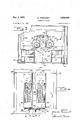
- FIG. 1 is a perspective view of one form of my chromatic clock.
- FIG. 2 is a sectional view of the form of my chromatic clock illustrated in FIG. l taken along the line 2-2 of FIG. l and drawn on an enlarged scale.
- FIG. 3 is a sectional view of my chromatic clock taken along the line 3 3 of FIG. 2.
- FIG. 4 is a sectional view of the works of my chromatic clock removed from the case.
- FIG. 5 is a fragmentary sectional view of my chromatic clock taken along the line 5 5 of FIG. 4, drawn on an enlarged scale, and viewed from the rear.
- FIG. 6 is a perspective view of a color coded cylinder which I employ in my chromatic clock.
- FIG. 7 is a front elevation of my chromatic clock illustrating its condition at one particular time.
- FIG. 8 is -a front elevation of my chromatic clock at another particular time with a part broken away to illustrate some of the details ofthe mechanism.
- my chromatic clock indicated generally by the reference character 10 includes an outer case or housing which may be boxlike in shape and which may include afront 12, a back 14, sides 16 and 18 and a top 20 with the bottom being open to permit insertion and removal of the operating mechanism to be described.
- the operating mechanism of my clock to be described hereinafter is supported on a frame indicated generally by the reference character 24 located within the housing of the clock.
- the frame may include four corner posts 24, 26, 28 and 30, laterally extending front and back upper connectors 32 and 34, and laterally extending lower connectors 36 and 38.
- the frame 24 includes front to back connectors 39 and 40 at ythe top and 42 and 44 at the bottom.
- the framework 24 thus far described is by way of example only.
- the individual members thereof may be formed by angles of aluminum or the like connected by any suitable means such, for example, as rivets or nuts and bolts or the like.
- baille 46 with a generally cylindrical extension 48 running from baille 46 toward the front 12.
- Frame 24 positions a plate 50 formed from frosted glass or plastic adjacent the front 12 behind the opening 22 so as to will be stepped through cover the same.
- Batlle 48 deilnes a generally circular area 52 on the face of the plate 50.
- Frame 24 supports a second baille comprising a ring 54 extending around the periphery of opening 22 inside the plate 50.
- Bafile S4 carries a plurality of generally radially extending -vanes 56 which are positioned between baille 48 and the baille S4. Vanes 56 divide the annular portion of the face of plate 50 between area 52 and the edge of opening 22 into a number of segments corresponding to the number of hours to be displayed to the observer. In the particular embodiment in the drawings I have shown a number of vanes 56 which provide twelve segments corresponding to the twelve hours of the conventional clock face.
- I mount a illter plate 58 on the inner edge of baille 54 and surrounding the baille 48. I so treat the portions of the lilter 58 between pairs of adjacent bailles 56 as to cause the areas of plate 50 between the pairs of baille to assume respective distinctive colors when the back of plate 58 is illuminated.
- the plate 58 may be transparent and the segmental surfaces thereof may be painted so as to transmit only certain respective colors.
- illms of illter material of different colors may be adhered to the segmental surfaces of the plate by a suitable transparent adhesive.
- I provide my clock with means for illuminatign the back of the plate 58 when the clock is in operation so as to illuminate the -various segments on the face of plate 50 with transmitted light of different colors indicating the various hours around the clock face.
- an arrangement of three fluorescent lamps 60, 62 and 64 are mounted in a generally triangular orientation on baille 46 in the space -between baille 46 and plate 58.
- plate 58 is so treated as to cause the respective segments of the annular area on the face of plate 50 to be illuminated with different colors when the lamps 60, 62 and 64 are lighted.
- the segment 66 at the top of the clock at a location corresponding to the twelfth hour may be white.
- the other segments 66 around the face in a clockwise direction and corresponding respectively to the hours one to eleven may be colored heliotrope, brown, light green, red, yellow, dark green, Vermillion, violet, gray, pink and blue as indicated by the hatching in the drawings.
- I provide my clock with means for sequentially illuminating area 52 in colors corresponding to the colors of the segmental areas 66 as the hours of the day pass.
- a platform 68 carried by frame members 42 and 44 carries respective bearings 70 and 73 which rotatably support shafts-74 and 76 carrying vertically disposed cylindrical filters 78 and 80 for rotatable movement around spaced vertical axes.
- a third shaft 82 located on platform 68 between shafts 74 and 76 carries a gear 84 which meshes with and drives respective gears 86 and 88 on shafts 74 and 76 when the shaft 82 is driven.
- I mount a sprocket wheel 90 on shaft 82 for rotation therewith. I provide the sprocket wheel 90 with twelve teeth 92 so that when wheel 90 is driven through the distance between a pair of adjacent teeth 92 the drums or lters 78 and 80 1/12 of a revolution in opposite directions.
- a crossbar 94 extending between two of the upper frame members carries spaced guides 96 and 98 for receiving and guiding the upper ends of the two drums 78 and 80.
- I mount respective cylindrical ballles 100 and 102 on guides 96 and 98.
- -I mount respective lamps 104 and 106 within the bailles 100 and 102.
- the angular extent of the slits 108 and 110 is such that each covers approximately one-twelfth of the angular extent cach of the drums 78 and 80 around its axis of rotation.
- each of the drums 78 and 80 may be made of glass or of a transparent plastic the regions 112 of which are painted or have colored illms applied thereto to cause them to transmit light of the desired color.
- the drums 78 and 80 may be made of glass or of a transparent plastic the regions 112 of which are painted or have colored illms applied thereto to cause them to transmit light of the desired color.
- the colors of successive areas of one drum as viewed from the top in one direction are the same as the colors of the areas of the other drum in the opposite direction.
- the arrangement is such that at any particular time areas 112 of the same color on the two drums 78 and 80 are behind the slits 108 and 1.10 so that the central area 32 is illuminated by light from lamps 104 and 106 passing ilrst through slits 106 and 108, then through the areas 112 behind the slits and finally through the extension 48 of baille 46 to the inner surface of plate 50 in the central area thereof.
- I mount ⁇ an arm 114 on the frame adjacent the bottom of one of the cylinders such, for example, as cylinders 80.
- I form the arm 114 of a suitable resilient material so as to be urged into engagement with the surface of the cylinder.
- a detent tooth 116 on the arm 1'14 is adapted to engage in respective detent recesses 118 in the surface of drum 80 below the regions 112.
- I provide as many detent recesses 118 as there are regions 112 on each of the drums. In the particular embodiment shown there will be twelve recesses corresponding to the twelve segments of a drum.
- An upright 120 on bracket 68 supports a clock mechanism 122 of any suitable type known to the art.
- the clockwork 122 is a synchronous clock motor having a shaft 124 which completes a revolution once each hour.
- Shaft 124 extends from a motor 122 through an opening 126 in plate 50.
- the end of the shaft 124 outside plate 50 carries a minute hand 128 which, as will be explained hereinafter, cooperates with the segments 66 to indicate the time within ilve minute intervals.
- I mount a crank arm 130 on shaft 124 between the upright 120 and the cylinders 78 and 80.
- Arm 130 is sufficiently long that once in the course of each revolution of shaft 12.4 it engages in the space between a pair of adjacent teeth to drive sprocket wheel 90 through one-twelfth of a revolution thus to indicate that the hour has changed.
- I mount a guide i132 at the bottom of the frame so as to ensure the engagement of crank 130 with the teeth 92.
- my clock In operation of my clock, it is ilrst plugged in to energize motor 122 and to light bulbs 60, 62, 64, 104 and 106.
- the minute hand 128 is rotated to drive shaft 124 to cause crank 130 to drive sprocket wheel 90 to rotate cylinders 78 and 80 ⁇ until area 52 is illuminated with a color corresponding to the color of the particular hour during which the clock is being set.
- the minute hand 128 is then moved to a position within one of the outer segments 66 which corresponds to the minute of the hour. While all of the segments 66 remain illuminated with the respective colors, the central aren 52 is illunniL1 nated only with that color corresponding to the present hour.
- the central area blends into the correspondingly illuminated segmental area 66 to produce a substantially homogeneous pattern of light shaped similarly to a keyhole with the pattern pointing to a location on the clock face at which the numeral indicating the particular hour of the day would be located on a conventionalclock face.
- the inner area 152 is illuminated With brown light to correspond to the color of the brown segment which is positioned at the location at which the numeral two normally would be located.
- the minute hand 128 ⁇ cooperates 'with the outer segments to indicate the minute of the second hour.
- the clock indicates half-past two.
- crank 130 enters into the'space between a pair of adjacent teeth 92 to rotate sprocket wheel 90 in a counterclockwise direction as viewed in FIG. 3 to rotate the two drums or filter cylinders 78 and 80 respectively in a clockwise direction and in a counterclockwise direction as viewed in FIG. 3.
- crank 130 leaves the tooth 9'2 which it had engaged during the action of driving sprocket 90, detent 116 falls into the next recess 118 accurately to locate the cylinders 78 and 80.
- crank 130 ⁇ and hand K128i on shaft 124 that the center area 52 just changes color as hand 128 points vertically upward.
- regions 112 providing a light green color move into positions behind slits 108 and 110 as the hour changes fromY two oclock to three oclock so that during the three oclock hour area 52 is light green to match the light green segment 66 located on the face at the position 'which normally would be occupied by the numeral three.
- center area 52 changing sequentially from light green to red to yellow, to green, to Vermillion, to violet, to gray, to pink, to blue, to white and to heliotrope as the hour changes from three, to four, to llve, to six, to seven, to eight, to nine, to ten, to eleven, to twelve and to one.
- FIG. 7 a time of approximately seven and one-half minutes after five whereat the center area 512 is yellow and the minute hand is at the dividing line between the heliotrope and brown segments.
- a clock including in combination, a face having a central area and a plurality of segmental secondary areas surrounding said central area and contiguous thereto, first means for .xedly coloring said secondary areas with respective distinct colors, and second means including a clock mechanism for sequentially coloring the central area with the colors of said secondary areas successively to provide a substantially continuous area in the shape of said central area and one of said secondary areas in the respective colors of said secondary areas.
- a clock as in claim 1 in which said central area is circular and in which said secondary areas are segments of an annulus surrounding said circular area.
- said ilrst coloring means comprises means for illuminating said secondary areas.
- said second coloring means comprises means for selectively illuminating said central area with the colors of said secondary areas.
- a chromatic clock including in combination, a face, means dividing said face into a central area and a plurality of secondary areas arranged around said central area at locations corresponding to the locations of the numerals of a conventional clock face, each of said secondary areas being contiguous to said central area, trst means for continuously illuminating said secondary areas with respective colors, and second means including timing means for sequentially illuminating said central area with colors corresponding to the colors of said secondary areas successively to provide a substantially continuous area in the shape of said central area and one of said secondary areas in the respective colors of said secondary areas.
- a chromatic clock as in claim 7 in which said dividing means comprises a light baille having an opening delimiting said central area, said second illuminating means comprising light projection means behind said baille opening.
- a chromatic clock as in claim 7 in which said dividing means comprises a light baille behind said face, said baille having an opening delimiting said central area, said second illuminating means comprising a scctioned rotatable light filter behind said opening, a lamp behind said lter and means responsive to said timing means for stepping said lter.
- a chromatic clock as in claim 7 in which said dividing means comprises a ⁇ baille behind said face, said baille having an opening delimiting said central area, said timing means having a shaft extending through said face, a minute hand on said shaft for cooperation with said secondary areas, said second illuminting means comprising a sectioned 'filter having sections corresponding to the colors of said secondary areas, means mounting said lter for rotary movement behind said opening, a light source behind said ilter and means responsive to movement of said shaft for stepping said filter.
- a chromatic clock as in claim 7 in which said dividing means comprises a first baille having an opening delimiting said central area, a generally cylindrical filter having a wall made up of a plurality of sections corresponding respectively in color to the colors of said secondary areas, means mounting said filter for rotary movement behind said opening, an auxiliary light bafiie within said filter, a light source within said auxiliary baffle, said auxiliary baffle having an opening between said source and said first am opening, said auxiliary baffle opening having a width adapted to restrict the passage of light to the width of one of said filter sections and means responsive to said timing means for driving said filter successively to position said sections adjacent said opening.
- a chromatic clock including in combination, a face, a first light baffle, means mounting said first light bafiie in spaced relationship to the back of said face, said first light bafiie having a central opening therein, a second light bafiie extending around said opening from said first baiiie to the back of the face to delirnit a central area of said face, a plurality of third light bafes extending radially outwardly from said second baffle at spaced locations therearound to delirnit a plurality of secondary areas on said face contiguous to and extending radially outwardly from said central area, a first light Ifilter between said first baffie and said face and around said second baffle adjacent said third baffies, said first filter havin-g a plurality of sections of different colors corresponding to the respective secondary areas, first illuminating means located between said first filter and said first bafiie, a second filter positioned behind said first am adjacent the first bafiie
- a clock as in claim 12 in which said clock mechanism comprises a shaft extending through said face, and a minute hand carried by said shaft adjacent said face for cooperation with the secondary areas of said face.
- a clock as in claim 13 in which said second filter is located adjacent the first baffle opening at one side of said shaft, said clock including a third filter similar to said second filter, said third filter positioned adjacent said first bafiie opening at the other side of said shaft, a third light source behind said third filter, a fifth bafiie between said third light source and said third filter, said fifth bafe having an opening adjacent to said ⁇ first baffle opening and means responsive to said clock mechanism for stepping said third filter successively to position its segments adjacent the opening in said fifth bafiie.
Landscapes
- Physics & Mathematics (AREA)
- General Physics & Mathematics (AREA)
- Electric Clocks (AREA)
Abstract
A CHROMATIC CLOCK IN WHICH TWELVE SEGMENTS OF AN ANNULAR SPACE ON THE CLOCK FACE ARE CONTINUOUSLY ILLUMINATED WITH DIFFERENT RESPECTIVE COLORS AND IN WHICH THE ENCLOSED CIRCULAR SPACE IS SEQUENTIALLY ILLUMINATED WITH COLORS MATCHING THOSE OF THE SEGMENTS AS THE HOURS PASS SO THAT AN OBSERVER IS IMMEDIATELY MADE AWARE OF THE HOUR OF THE DAY. A MINUTE HAND COOPERATES WITH THE SEGMENTS OF THE ANNULUS IMMEDIATELY TO MAKE THE OBSERVER AWARE OF THE PARTICULAR FIVE-MINUTE INTERVAL OF THE HOUR.
Description
3 Sheets-Sheet 1 I/vv'smo@ H Trang/5 ys NOV- 2, 1971 y M. REsNlcoFF GHROMATIC CLOCK Filed March 12, 1970 E /32 Moran ReSfI/'Caf/ M. RESNICOFF CHROMATIC CLOCK Nov. 2, 1971 3 Sheets-Sheet 3 rFiled March l2 1970 NVE'NTR Maffe/7 Resn/'ca/'f nited States Patent 3,616,640 CHROMATIC CLOCK Morton Resnicol, New York, N.Y., assignor to Art Cycle Inc. Filed Mar. 12, 1970, Ser. No. 18,911 Int. Cl. G04b 19/30 U.S. Cl. 58-50 14 Claims ABSTRACT OF THE DISCLOSURE A chromatic clock in which twelve segments of an annular space on the clock face `are continuously illuminated with different respective colors and in which the enclosed circular space is sequentially illuminated with colors matching those of the segments as the hours pass so that an observer is immediately made aware of the hour of the day. A minute hand cooperates with the segments of the annulus immediately to make the observer laware of the particular five-minute interv-al of the hour.
BACKGROUND OF THE INVENTION Many attempts have been made in the prior art to present an observer with a more attractive indication of time. A large number of these attempts involve the use of light. For example, various schemes have been proposed for illuminating clock dials. In other systems either an image of the dial face or an image of numerals indicating the time is projected on a surface. The projection may, moreover, be in diEerent colors. While systems of this sort are somewhat more pleasing than the ordinary clock face they have relatively little aesthetic value.
`One particular system shown in U.S. Pat. 3,439,492 goes a step further than the systems of the prior art described above in that it presents an indication of the hour at a particular location on the clock face, with each hour being indicated by a distinctive color. At a second location on the clock face the present live-minute interval within the hour is indicated in color. At a third location on the clock face there is presented a blend of the two colors which individually respectively indicate the hour and the veminute interval. In order that the observer may decipher the indications, there the clock face carries a color code comprising painted colored areas arranged in a circle around the clock face.
While the system just described presents a more pleasing and appealing appearance than do the earlier systems, it is inconvenient to use for it requires two distinct observations and mental operations on the part ofthe observer to decipher the indications of time. First, one must note the color presented at the hour indicating location and then search the code to associate the presented color with one of the code colors thus to determine the hour. The same operation must be repeated for the five-minute indication at the live-minute location. It will readily be appreciated that the blend of colors presented at the third location is not readily decipherable since it may be one among one hundred and forty-four possible hues.
I have invented a chromatic clock which overcomes the defects of clocks of the prior art described hereinabove. My clock provides the observer with an attractive time display having a high degree of aesthetic value. It does not require the observer rst to note a color at one location land then search a code occupying other locations to determine time. Rather, it immediately informs the observer of the time. It is relatively simple in construction for the result achieved.
SUMMARY `OF THE INVENTION One object of my invention is to provide a chromatic ice clock which displays time in a manner having a high degree of aesthetic appeal.
Another object of my invention is to provide a chromatic clock which provides a more attractive display of time than do clocks of the prior art.
A further object of my invention is to provide a chromatic clock which immediately makes the observer aware of the time without requiring him to 4associate a display indication at one location with a code occupying other locations.
A still further object of my invention is to provide a chromatic clock which is simple in construction and in operation.
,Other and further objects of my invention will appear from the following description.
BRIEF DESCRIPTION OF THE DRAWINGS In the accompanying drawings which form part of the instant specification and which are to be read in conjunction therewith and in which like reference numerals are used to indicate like parts in the various views:
FIG. 1 is a perspective view of one form of my chromatic clock.
FIG. 2 is a sectional view of the form of my chromatic clock illustrated in FIG. l taken along the line 2-2 of FIG. l and drawn on an enlarged scale.
FIG. 3 is a sectional view of my chromatic clock taken along the line 3 3 of FIG. 2.
FIG. 4 is a sectional view of the works of my chromatic clock removed from the case.
FIG. 5 is a fragmentary sectional view of my chromatic clock taken along the line 5 5 of FIG. 4, drawn on an enlarged scale, and viewed from the rear.
FIG. 6 is a perspective view of a color coded cylinder which I employ in my chromatic clock.
FIG. 7 is a front elevation of my chromatic clock illustrating its condition at one particular time.
FIG. 8 is -a front elevation of my chromatic clock at another particular time with a part broken away to illustrate some of the details ofthe mechanism.
DESCRIPTION OF .THE PREFERRED EMBODIMENT Referring now to the drawings my chromatic clock indicated generally by the reference character 10 includes an outer case or housing which may be boxlike in shape and which may include afront 12, a back 14, sides 16 and 18 and a top 20 with the bottom being open to permit insertion and removal of the operating mechanism to be described. I form the front 12 With an opening 22 which, in the particular embodiment of my clock illustrated in the drawings, is circular. Y v
The operating mechanism of my clock to be described hereinafter is supported on a frame indicated generally by the reference character 24 located within the housing of the clock. By way of example the frame may include four corner posts 24, 26, 28 and 30, laterally extending front and back upper connectors 32 and 34, and laterally extending lower connectors 36 and 38. In addition, the frame 24 includes front to back connectors 39 and 40 at ythe top and 42 and 44 at the bottom. The framework 24 thus far described is by way of example only. The individual members thereof may be formed by angles of aluminum or the like connected by any suitable means such, for example, as rivets or nuts and bolts or the like. Frame 24 'supports a light baille 46 extending across the housing at a location between the front 12 and the back 14. We form baille 46 with a generally cylindrical extension 48 running from baille 46 toward the front 12. Frame 24 positions a plate 50 formed from frosted glass or plastic adjacent the front 12 behind the opening 22 so as to will be stepped through cover the same. Batlle 48 deilnes a generally circular area 52 on the face of the plate 50.
I mount a illter plate 58 on the inner edge of baille 54 and surrounding the baille 48. I so treat the portions of the lilter 58 between pairs of adjacent bailles 56 as to cause the areas of plate 50 between the pairs of baille to assume respective distinctive colors when the back of plate 58 is illuminated. This may be achieved in any suitable manner. For example, the plate 58 may be transparent and the segmental surfaces thereof may be painted so as to transmit only certain respective colors. Alternatively, illms of illter material of different colors may be adhered to the segmental surfaces of the plate by a suitable transparent adhesive.
I provide my clock with means for illuminatign the back of the plate 58 when the clock is in operation so as to illuminate the -various segments on the face of plate 50 with transmitted light of different colors indicating the various hours around the clock face. For example, an arrangement of three fluorescent lamps 60, 62 and 64 are mounted in a generally triangular orientation on baille 46 in the space -between baille 46 and plate 58.
As has been explained hereinabove, plate 58 is so treated as to cause the respective segments of the annular area on the face of plate 50 to be illuminated with different colors when the lamps 60, 62 and 64 are lighted. By way of example, the segment 66 at the top of the clock at a location corresponding to the twelfth hour may be white. The other segments 66 around the face in a clockwise direction and corresponding respectively to the hours one to eleven may be colored heliotrope, brown, light green, red, yellow, dark green, Vermillion, violet, gray, pink and blue as indicated by the hatching in the drawings. From the structure thus far described it will be seen that I have dividedthe face of the plate S which forms the face of my clock into a central generally circular area 52 surrounded by an annular region which is divided .up into twelve segmental areas 66 which are illuminated in various respective colors continuously during the operation of my clock.
I provide my clock with means for sequentially illuminating area 52 in colors corresponding to the colors of the segmental areas 66 as the hours of the day pass. A platform 68 carried by frame members 42 and 44 carries respective bearings 70 and 73 which rotatably support shafts-74 and 76 carrying vertically disposed cylindrical filters 78 and 80 for rotatable movement around spaced vertical axes. A third shaft 82 located on platform 68 between shafts 74 and 76 carries a gear 84 which meshes with and drives respective gears 86 and 88 on shafts 74 and 76 when the shaft 82 is driven. I mount a sprocket wheel 90 on shaft 82 for rotation therewith. I provide the sprocket wheel 90 with twelve teeth 92 so that when wheel 90 is driven through the distance between a pair of adjacent teeth 92 the drums or lters 78 and 80 1/12 of a revolution in opposite directions.
A crossbar 94 extending between two of the upper frame members carries spaced guides 96 and 98 for receiving and guiding the upper ends of the two drums 78 and 80. I mount respective cylindrical ballles 100 and 102 on guides 96 and 98. -I mount respective lamps 104 and 106 within the bailles 100 and 102. The baflles 100 and 102 are provided with respective Ivertically extending slits 108 and 110. =I so position the baffles 100 and 102 eccentrically of the axes of rotation of the drums 78 and 80 that the slits 108 and 110 are relatively closely adjacent to the inner surfaces of drums 78 and 80. The angular extent of the slits 108 and 110 is such that each covers approximately one-twelfth of the angular extent cach of the drums 78 and 80 around its axis of rotation.
I form the central portion of each of the drums 78 and with a plurality of regions 112 adapted respectively to transmit light of different colors. This may be achieved in any suitable manner similar to that which was employed to provide colored segments 66 on the plate 58. For example, the drums 78 and 80 may be made of glass or of a transparent plastic the regions 112 of which are painted or have colored illms applied thereto to cause them to transmit light of the desired color. In the particular embodiment which is illustrated in the drawings, there are twelve regions '112 around the periphery of each of the drums 7,8 and 80. Moreover, these areas correspond respectively in color to the colors of the segments 66 as is indicated by the hatching in the drawings. Owing to the fact that the drums rotate in opposite directions, the colors of successive areas of one drum as viewed from the top in one direction are the same as the colors of the areas of the other drum in the opposite direction. The arrangement is such that at any particular time areas 112 of the same color on the two drums 78 and 80 are behind the slits 108 and 1.10 so that the central area 32 is illuminated by light from lamps 104 and 106 passing ilrst through slits 106 and 108, then through the areas 112 behind the slits and finally through the extension 48 of baille 46 to the inner surface of plate 50 in the central area thereof.
In order to ensure that the two drums are accurately I mount `an arm 114 on the frame adjacent the bottom of one of the cylinders such, for example, as cylinders 80. I form the arm 114 of a suitable resilient material so as to be urged into engagement with the surface of the cylinder. A detent tooth 116 on the arm 1'14 is adapted to engage in respective detent recesses 118 in the surface of drum 80 below the regions 112. I provide as many detent recesses 118 as there are regions 112 on each of the drums. In the particular embodiment shown there will be twelve recesses corresponding to the twelve segments of a drum.
An upright 120 on bracket 68 supports a clock mechanism 122 of any suitable type known to the art. Preferably, the clockwork 122 is a synchronous clock motor having a shaft 124 which completes a revolution once each hour. Shaft 124 extends from a motor 122 through an opening 126 in plate 50. The end of the shaft 124 outside plate 50 carries a minute hand 128 which, as will be explained hereinafter, cooperates with the segments 66 to indicate the time within ilve minute intervals. I mount a crank arm 130 on shaft 124 between the upright 120 and the cylinders 78 and 80. Arm 130 is sufficiently long that once in the course of each revolution of shaft 12.4 it engages in the space between a pair of adjacent teeth to drive sprocket wheel 90 through one-twelfth of a revolution thus to indicate that the hour has changed. Preferably, I mount a guide i132 at the bottom of the frame so as to ensure the engagement of crank 130 with the teeth 92.
In operation of my clock, it is ilrst plugged in to energize motor 122 and to light bulbs 60, 62, 64, 104 and 106. Next, the minute hand 128 is rotated to drive shaft 124 to cause crank 130 to drive sprocket wheel 90 to rotate cylinders 78 and 80` until area 52 is illuminated with a color corresponding to the color of the particular hour during which the clock is being set. The minute hand 128 is then moved to a position within one of the outer segments 66 which corresponds to the minute of the hour. While all of the segments 66 remain illuminated with the respective colors, the central aren 52 is illunniL1 nated only with that color corresponding to the present hour. Moreover, the central area blends into the correspondingly illuminated segmental area 66 to produce a substantially homogeneous pattern of light shaped similarly to a keyhole with the pattern pointing to a location on the clock face at which the numeral indicating the particular hour of the day would be located on a conventionalclock face.
By way of example, in FIG. l during the second hour of the day the inner area 152 is illuminated With brown light to correspond to the color of the brown segment which is positioned at the location at which the numeral two normally would be located. At the same time the minute hand 128` cooperates 'with the outer segments to indicate the minute of the second hour. As is shown in FIG. 1 the clock indicates half-past two. As the motor continues to operate and as the end of the hour approaches, crank 130 enters into the'space between a pair of adjacent teeth 92 to rotate sprocket wheel 90 in a counterclockwise direction as viewed in FIG. 3 to rotate the two drums or filter cylinders 78 and 80 respectively in a clockwise direction and in a counterclockwise direction as viewed in FIG. 3. As the crank 130 leaves the tooth 9'2 which it had engaged during the action of driving sprocket 90, detent 116 falls into the next recess 118 accurately to locate the cylinders 78 and 80. I so position crank 130` and hand K128i on shaft 124 that the center area 52 just changes color as hand 128 points vertically upward. 'In the operation just described regions 112 providing a light green color move into positions behind slits 108 and 110 as the hour changes fromY two oclock to three oclock so that during the three oclock hour area 52 is light green to match the light green segment 66 located on the face at the position 'which normally would be occupied by the numeral three.
The above operation continues with the center area 52 changing sequentially from light green to red to yellow, to green, to Vermillion, to violet, to gray, to pink, to blue, to white and to heliotrope as the hour changes from three, to four, to llve, to six, to seven, to eight, to nine, to ten, to eleven, to twelve and to one. Further by way of illustrating the manner in which my clock immediately informs the observer of the hour, I have illustrated in FIG. 7 a time of approximately seven and one-half minutes after five whereat the center area 512 is yellow and the minute hand is at the dividing line between the heliotrope and brown segments. In FIG. 8 there is indicated a time of ten forty-five at which time the center area 52 is illuminated with blue to match the blue of the segment 66 located in the position on the face at which the number ten normally would be located. At the same time, the hand 128 is at the center of the gray segment which corresponds in location to that which normally would be occupied by the numeral nine. Any other time of the day is represented in like manner. It is further to be appreciated that while I have shown a form of my clock in which twelve hours are represented, I might as well so construct my clock as to provide twenty-four hours. for example.
,It will be seen that I have accomplished the objects of my invention. I have provided a chromatic clock which displays the time in an extremely attractive fashion. My chromatic clock immediately indicates in color the hour of the day without requiring any mental operation of associating a displayed color with a code which is remote from the color display. My clock further irnmediately indicates the minute of the hour: It does not require the observer to perform the extra mental operation of associating an hour color indication at one location with a code of color indications at various remote locations. It is simple in construction and operation for the result achieved thereby.
It lwill be understood that certain features and subcombinations are of utility and may be employed without reference toy other features and subcombinations.
This is contemplated by and is within the scope of my claims. It is further obvious that various changes may be made in details within the scope of my claims Without departing from the spirit of my invention. It is, therefore, to be understood that my invention is not to be limited to the specic details shown and described.
Having thus described my invention, what I claim is: 1. A clock including in combination, a face having a central area and a plurality of segmental secondary areas surrounding said central area and contiguous thereto, first means for .xedly coloring said secondary areas with respective distinct colors, and second means including a clock mechanism for sequentially coloring the central area with the colors of said secondary areas successively to provide a substantially continuous area in the shape of said central area and one of said secondary areas in the respective colors of said secondary areas. 2. A clock as in claim 1 in which said central area is circular.
3. A clock as in claim 1 in which said central area is circular and in which said secondary areas are segments of an annulus surrounding said circular area.
4. A clock as in claim 1 in which said ilrst coloring means comprises means for illuminating said secondary areas.
5. A clock as in claim 1 in which said second coloring means comprises means for selectively illuminating said central area with the colors of said secondary areas.
`6. A clock as in claim 1 in which said ilrst coloring means comprises means for illuminating said secondary areas with said respective distinct colors in which said second coloring means comprises vmeans for selectively illuminating said central area with the colors of said secondary areas.
7. A chromatic clock including in combination, a face, means dividing said face into a central area and a plurality of secondary areas arranged around said central area at locations corresponding to the locations of the numerals of a conventional clock face, each of said secondary areas being contiguous to said central area, trst means for continuously illuminating said secondary areas with respective colors, and second means including timing means for sequentially illuminating said central area with colors corresponding to the colors of said secondary areas successively to provide a substantially continuous area in the shape of said central area and one of said secondary areas in the respective colors of said secondary areas.
8. A chromatic clock as in claim 7 in which said dividing means comprises a light baille having an opening delimiting said central area, said second illuminating means comprising light projection means behind said baille opening.
9. A chromatic clock as in claim 7 in which said dividing means comprises a light baille behind said face, said baille having an opening delimiting said central area, said second illuminating means comprising a scctioned rotatable light filter behind said opening, a lamp behind said lter and means responsive to said timing means for stepping said lter.
10. A chromatic clock as in claim 7 in which said dividing means comprises a `baille behind said face, said baille having an opening delimiting said central area, said timing means having a shaft extending through said face, a minute hand on said shaft for cooperation with said secondary areas, said second illuminting means comprising a sectioned 'filter having sections corresponding to the colors of said secondary areas, means mounting said lter for rotary movement behind said opening, a light source behind said ilter and means responsive to movement of said shaft for stepping said filter.
11. A chromatic clock as in claim 7 in which said dividing means comprises a first baille having an opening delimiting said central area, a generally cylindrical filter having a wall made up of a plurality of sections corresponding respectively in color to the colors of said secondary areas, means mounting said filter for rotary movement behind said opening, an auxiliary light bafiie within said filter, a light source within said auxiliary baffle, said auxiliary baffle having an opening between said source and said first baie opening, said auxiliary baffle opening having a width adapted to restrict the passage of light to the width of one of said filter sections and means responsive to said timing means for driving said filter successively to position said sections adjacent said opening.
12. A chromatic clock including in combination, a face, a first light baffle, means mounting said first light bafiie in spaced relationship to the back of said face, said first light bafiie having a central opening therein, a second light bafiie extending around said opening from said first baiiie to the back of the face to delirnit a central area of said face, a plurality of third light bafes extending radially outwardly from said second baffle at spaced locations therearound to delirnit a plurality of secondary areas on said face contiguous to and extending radially outwardly from said central area, a first light Ifilter between said first baffie and said face and around said second baffle adjacent said third baffies, said first filter havin-g a plurality of sections of different colors corresponding to the respective secondary areas, first illuminating means located between said first filter and said first bafiie, a second filter positioned behind said first baie adjacent the first bafiie opening, said second filter having sections corresponding in number and color to the sections of the first filter, a second light source positioned 'behind said second filter, a fourth baflie positioned between said second light source and said second filter, said fourth baffle having an opening adjacent first baffle opening and a clock mechanism for stepping said second filter sequentially to position the sections thereof adjacent the fourth bafiie opening.
13. A clock as in claim 12 in which said clock mechanism comprises a shaft extending through said face, and a minute hand carried by said shaft adjacent said face for cooperation with the secondary areas of said face.
14. A clock as in claim 13 in which said second filter is located adjacent the first baffle opening at one side of said shaft, said clock including a third filter similar to said second filter, said third filter positioned adjacent said first bafiie opening at the other side of said shaft, a third light source behind said third filter, a fifth bafiie between said third light source and said third filter, said fifth bafe having an opening adjacent to said `first baffle opening and means responsive to said clock mechanism for stepping said third filter successively to position its segments adjacent the opening in said fifth bafiie.
References Cited UNITED STATES PATENTS 1,938,417 12/1933 Curran 58-50 3,439,492 3/1969 Graveson 58-1 RICHARD B. WILKINSON, Primary Examiner E. C. SIMMONS, Assistant Examiner U.S. Cl. X.R. 24U- 6.43
Applications Claiming Priority (1)
| Application Number | Priority Date | Filing Date | Title |
|---|---|---|---|
| US1891170A | 1970-03-12 | 1970-03-12 |
Publications (1)
| Publication Number | Publication Date |
|---|---|
| US3616640A true US3616640A (en) | 1971-11-02 |
Family
ID=21790388
Family Applications (1)
| Application Number | Title | Priority Date | Filing Date |
|---|---|---|---|
| US18911A Expired - Lifetime US3616640A (en) | 1970-03-12 | 1970-03-12 | Chromatic clock |
Country Status (1)
| Country | Link |
|---|---|
| US (1) | US3616640A (en) |
Cited By (9)
| Publication number | Priority date | Publication date | Assignee | Title |
|---|---|---|---|---|
| US3798892A (en) * | 1971-12-29 | 1974-03-26 | V Lukens | Clock mechanism |
| US4373822A (en) * | 1979-06-28 | 1983-02-15 | Tkac Frank S | Clock with selective visual alarm indicators |
| USD271288S (en) | 1981-07-22 | 1983-11-08 | Bernick Herman C | Clock face or similar article |
| US5051969A (en) * | 1989-11-27 | 1991-09-24 | Chien Hua Glass Co., Ltd. | Decorative clock with rotatable sand picture |
| US20030211999A1 (en) * | 2002-03-15 | 2003-11-13 | Gellman Samuel H. | Polypeptides containing gamma-amino acids |
| WO2005022277A1 (en) * | 2003-09-01 | 2005-03-10 | Mayhem Uk Limited | Chromatic clock |
| US7079452B2 (en) * | 2002-04-16 | 2006-07-18 | Harrison Shelton E | Time display system, method and device |
| US20080165629A1 (en) * | 2006-12-19 | 2008-07-10 | Billeaudeaux Michael A | Color time |
| US20090201772A1 (en) * | 2006-12-19 | 2009-08-13 | Billeaudeaux Michael A | Systems and methods for providing time using colors |
-
1970
- 1970-03-12 US US18911A patent/US3616640A/en not_active Expired - Lifetime
Cited By (11)
| Publication number | Priority date | Publication date | Assignee | Title |
|---|---|---|---|---|
| US3798892A (en) * | 1971-12-29 | 1974-03-26 | V Lukens | Clock mechanism |
| US4373822A (en) * | 1979-06-28 | 1983-02-15 | Tkac Frank S | Clock with selective visual alarm indicators |
| USD271288S (en) | 1981-07-22 | 1983-11-08 | Bernick Herman C | Clock face or similar article |
| US5051969A (en) * | 1989-11-27 | 1991-09-24 | Chien Hua Glass Co., Ltd. | Decorative clock with rotatable sand picture |
| US20030211999A1 (en) * | 2002-03-15 | 2003-11-13 | Gellman Samuel H. | Polypeptides containing gamma-amino acids |
| US7079452B2 (en) * | 2002-04-16 | 2006-07-18 | Harrison Shelton E | Time display system, method and device |
| US20070189123A1 (en) * | 2002-04-16 | 2007-08-16 | Harrison Shelton E Jr | Time display system, method and device |
| US7525877B2 (en) * | 2002-04-16 | 2009-04-28 | Harrison Jr Shelton E | Time display system, method and device |
| WO2005022277A1 (en) * | 2003-09-01 | 2005-03-10 | Mayhem Uk Limited | Chromatic clock |
| US20080165629A1 (en) * | 2006-12-19 | 2008-07-10 | Billeaudeaux Michael A | Color time |
| US20090201772A1 (en) * | 2006-12-19 | 2009-08-13 | Billeaudeaux Michael A | Systems and methods for providing time using colors |
Similar Documents
| Publication | Publication Date | Title |
|---|---|---|
| US3439492A (en) | Chromoclock | |
| US4920524A (en) | Multimode digital timepiece | |
| US5943300A (en) | Timepiece having disks of graduated design density | |
| EP1988432B1 (en) | Watch comprising a hand-free display | |
| US2243343A (en) | Clock | |
| US3956879A (en) | Time indicating device | |
| US3270201A (en) | Photo-luminescent display means | |
| US3616640A (en) | Chromatic clock | |
| US3854279A (en) | Method and apparatus for indicating time in terms of color | |
| US4022015A (en) | Time indicating device | |
| US3992872A (en) | Display device | |
| US3983688A (en) | World clock device | |
| US4279031A (en) | Luminous clock display using optical fibers | |
| US3694645A (en) | Kinetic display | |
| US3593517A (en) | Illuminated disk clock face | |
| US4274154A (en) | Luminous clock display using optical fibers | |
| US3849978A (en) | Time indicating means | |
| US1994950A (en) | Illuminated dial | |
| US4092823A (en) | Timepiece having display cylinders | |
| US2576119A (en) | Wall and desk cyclometer clock | |
| US2444392A (en) | Three-dimensional time indicator clock | |
| US2201093A (en) | Illuminating device | |
| US3859782A (en) | Clock with illumination device | |
| US2875668A (en) | Projector for time indications | |
| US2547468A (en) | Second-marking clock |