US361663A - Electric-arc lamp - Google Patents
Electric-arc lamp Download PDFInfo
- Publication number
- US361663A US361663A US361663DA US361663A US 361663 A US361663 A US 361663A US 361663D A US361663D A US 361663DA US 361663 A US361663 A US 361663A
- Authority
- US
- United States
- Prior art keywords
- frame
- escapement
- lamp
- carbon
- electric
- Prior art date
- Legal status (The legal status is an assumption and is not a legal conclusion. Google has not performed a legal analysis and makes no representation as to the accuracy of the status listed.)
- Expired - Lifetime
Links
- 238000010891 electric arc Methods 0.000 title description 6
- 229910052799 carbon Inorganic materials 0.000 description 13
- OKTJSMMVPCPJKN-UHFFFAOYSA-N Carbon Chemical compound [C] OKTJSMMVPCPJKN-UHFFFAOYSA-N 0.000 description 12
- 230000007246 mechanism Effects 0.000 description 4
- 230000001105 regulatory effect Effects 0.000 description 3
- 230000000994 depressogenic effect Effects 0.000 description 2
- XEEYBQQBJWHFJM-UHFFFAOYSA-N iron Substances [Fe] XEEYBQQBJWHFJM-UHFFFAOYSA-N 0.000 description 2
- 229910052742 iron Inorganic materials 0.000 description 2
- 241001123248 Arma Species 0.000 description 1
- 238000013459 approach Methods 0.000 description 1
- 150000001721 carbon Chemical class 0.000 description 1
- 238000010276 construction Methods 0.000 description 1
- 230000001276 controlling effect Effects 0.000 description 1
- 230000003247 decreasing effect Effects 0.000 description 1
- 230000005611 electricity Effects 0.000 description 1
Images
Classifications
-
- H—ELECTRICITY
- H05—ELECTRIC TECHNIQUES NOT OTHERWISE PROVIDED FOR
- H05B—ELECTRIC HEATING; ELECTRIC LIGHT SOURCES NOT OTHERWISE PROVIDED FOR; CIRCUIT ARRANGEMENTS FOR ELECTRIC LIGHT SOURCES, IN GENERAL
- H05B31/00—Electric arc lamps
- H05B31/02—Details
- H05B31/18—Mountings for electrodes; Electrode feeding devices
Definitions
- My invention relates to certain improvements in electric-arc lamps, and it consists in the construction and combination of devices, which I shall hereinafter fully describe and claim.
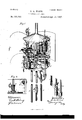
- Figure l is a view of the lamp with the mechanism attached.
- Fig. 2 is a transverse section of the positive carbon, carrying-rod, and pawl and ratchet.
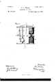
- Fig. 3 is a section showing the oscillating arms of the escapement and the adjustable stop, also the magnets and frame M.
- the geanwheel I engages with a pinion, K,
- Arms m m extend vertically upward and downward from the shaft P, the upper one having an adjustable weight, Q, fixed upon it, so as to regulate the speed at which the escapement moves, while the lower one engages an eccentric or stop, a, when it is desired to stop the movement of the escapement.
- the outer end of the frame M has a crossbar connected with the soft-iron bar or core R, which extends vertically upward into the coil S and downward into the coil IV, hereinafter described, these coils being rendered temporarily magnetic when the current passes through them.
- U is an arm extending upward from the frame M
- U is a lever fulcrumed to the upper plate E of the apparatus, having one end connected witlrthe arm T, and having an adjustable weight upon its opposite end, so as to partially counterbalance the weight of the frame and the gear wheels upon it.
- the weight V may be moved upon the lever U, so as to adjust the weight to the power which it is desired that the magnet shall have before moving the frame.
- the weight of the frame M is counterbalanced by the weighted lever U, so that the varying power of the two magnets S and ⁇ V will act upon the core R and move the frame M, as above described.
- the stop a is shown in the present case as an cecentric disk mounted upon a shaft, with a screw, by which it is adjusted to act with any desired movement of the escapement-carrying frame.
- the coil'of fine wire forming the electro-magnet XV stands in line below the coil S, as before described, and has the wires X connecting with it from the main wires of the lamp, as shown.
- Y is a small electro-magnet, having an armature, Z, fixed to a lever-arm, a, so as to stand just above the end of the electromagnet Y.
- the outer end of this lever-arm is fulcrumed to a post, I), which has a wire, 0, connecting it directly with one of the main wires of the lamp between its point of entrance into the lamp and the coil S, by which the device is regulated.
- d is a post extending upward from the lower plate E to a point near the center of the lever to, but not forming a contact with the lever unless the arma ture is drawn down into contact with the core of the magnet.
- This post has a wire, 0, extending from it to another one of the main wires, so that when the armature is drawn down a contact is made between the lever-arm a and the top of the post d and direct communication is formed between. the positive and negative main wires of the lamp without passing through the carbons, and the lamp is thus cut out of the circuit.
- f are wires, one of which connects with the electro-magnet WV and the other with the main wire D, these two wiresf connecting with the coil or electro-magnet Y, and when by any reason the tension of the current becomes .00 great a sufficient portion of the current vill pass through these wires to cause the electromagnet Y to act to draw the armature Z downward, thus producing a connection between the lever-arm a and the post (Z and through the wires and c, forming a direct communication between the main wires of the lamp, thus cutting it out of the circuit automatically.
- the positive main wire D of the upper carbon enters the suspending-rod F and passes downward through it, and thence upward through the lower plate E of the apparatus and into a binding-post, g, from which the wire, 0, for cutting out is led, as before described. Thence from this binding-post the main wire leads into and forms the coil S, which, with the finer coil W, operates the oscillating frame M of the escapement, and passes out to a screw, it, upon the upper plate E, from which, through one of the posts which unite the two plates E, the current passes, and thence through the elastic plate or brush i, the end of which rests against the positive carbon-carrying rod G.
- the negative wire 1) for the lower carbon enters, as before described, through the opposite one of the suspendingrods F, passing downward through it, thence upward through the bottom plate E, and into a binding-post, j, from whence it passes downward through the side of the rod A, as before described. From the binding-postj the wire, 0, for cutting out leads to the postd, as before described, below the plate.
- the posts a and d pass through the lower plate E of the device, and a switch, 1:, serves to unite them when it is desired to cut the lamp out of the circuit for any purpose without waiting for it to be done automatically.
- the lamp here shown is an outdoor one, designed to have a cover or case; but an indoor lamp may be suspended from a central rod, and the main wires may lead directly into the lamp-case.
- the lower stationary carbon and the upper movable one with the controlling escapement, gearing, and pinion by which the rack carrying the upper carbon is allowed to move downward by gravitation, in combination with a frame horizontally fulcrumed, and having the escapement pivoted upon one side of its fulcrum and the escapement-wheel upon the opposite side, and an electro-magnet with which one end of the frameis connected, so as to be raised and throw the escapement out of action, substantially as herein described.
- the horizontallyfulcrumed frame having one end connected with the armature of the magnets, wherebyit is raised or depressed by the varying resistance of the current, in combination with the vibrating escapement pivoted upon one side of the fulcrum about which the frame moves, the escapemcnt-wheel with which it engages, journaled upon the opposite side of said fuleru m, and the eccentric or adjustable stop tally fulcrumed, having one end attached to the armature of the magnets, by the varying resistance of which the frame is tilted about its fulcrum, the escapenient-wheel journaled upon one side of the fulcrum, and the vibratin g escapement pivoted upon the opposite side,
Landscapes
- Electromagnets (AREA)
Description
2 Sheets-Sheet l.
G. A. WIESE.
ELECTRIC ARC LAMP.
(No Mqd-el.)
No; 361,663. Patented Apr. 19, 1887.
lllm llll llllllllllll illlllllllllllflzfilv 6 (No M0de-1.) 2 sheets-sheet 2. G. A. WIESE.
ELECTRIC ARC LAMP. No. 361.663. Patented Apr. 19, 1887.
' inion ear GUSTAV A. IVIESE, OF SAN FRANCISCO, CALIFORNIA.
ELECTRIC-ARC LAMP.
SPECIFICATION forming part of Letters Patent No. 361,663,
dated April 19, 1887.
Application filed Novcmberfil', 1886. Serial No. 220,096. (No model.)
To aZZ whom it may concern:
Be'it known that I, GUSTAV A. WIEsE, of the city and county'of San Francisco, State of California, have invented an Improvement in Electric-Arc Lamps; and Ihereby declare the following to be a full, clear, and exact description of the same.
My invention relates to certain improvements in electric-arc lamps, and it consists in the construction and combination of devices, which I shall hereinafter fully describe and claim.
Figure l is a view of the lamp with the mechanism attached. Fig. 2 is a transverse section of the positive carbon, carrying-rod, and pawl and ratchet. Fig. 3 is a section showing the oscillating arms of the escapement and the adjustable stop, also the magnets and frame M.
A Aare the side rods of an electric-arc lamp, having the lower ends united by the yoke B, from the center of which a socket, O, arises, within which the lower or negative carbon is secured by a set-screw; and D is the negative wire connecting with this carbon, and it is led, for convenience, through one of the hollow side rods, A, up through the plate.
E of the regulating mechanism, being carried from thence upward and outward through the suspending-rod F, so as to be connected with the circuit in the usual manner.
- Upon the lower plate or table E to which the side rods, A, are secured, is supported the regulating mechanism. Through the center 'of this plate the rod G slides freely, the lower end being provided with a socket to receive and hold the upper adjustable or positive carbon of the are.
One side of this red has rack-teeth, which engage with corresponding teeth of a pinion,
H, upon the horizontal shaft of the gear-wheel I. This pinion turns loosely upon the shaft,and
is connected by'means of a pawl and ratchet, J, with the gear-wheel I, so that when the weight of the carbon-suspending rod is brought upon the pinion it causes the latter and the gear-wheel to rotate, and when it is desired to slip the rod up it is pushed up, and the pinion will rotate independently of the gear-wheel by turning loosely upon the shaft.-
The geanwheel I engages with a pinion, K,
upon the shaft of the escapement-wheel L. The shafts of all these wheels are j ournaled in the sides of a frame, M, which is pivoted between two vertical posts, N, extending between the upper and lower plates E. The pivotpoints about which this frame moves are situated just behind the shaft of the escapementwheel, so that the frame may be moved up and down about the points. 0 is the escapement which engages the teeth of the wheel L, the escapement being fixed upon a shaft, I, which is also journaled in the frame M, but upon the opposite side of its fulcrum from the shafts of the gear-wheel I and the escapementwheel L.
Arms m m extend vertically upward and downward from the shaft P, the upper one having an adjustable weight, Q, fixed upon it, so as to regulate the speed at which the escapement moves, while the lower one engages an eccentric or stop, a, when it is desired to stop the movement of the escapement.
The outer end of the frame M has a crossbar connected with the soft-iron bar or core R, which extends vertically upward into the coil S and downward into the coil IV, hereinafter described, these coils being rendered temporarily magnetic when the current passes through them.
1 is an arm extending upward from the frame M, and U is a lever fulcrumed to the upper plate E of the apparatus, having one end connected witlrthe arm T, and having an adjustable weight upon its opposite end, so as to partially counterbalance the weight of the frame and the gear wheels upon it. The weight V may be moved upon the lever U, so as to adjust the weight to the power which it is desired that the magnet shall have before moving the frame. I
The operation of this device will be as follows: When the frame stands in its normal position,the escapement and escapementwheels, the shafts of which are upon opposite sides of the fulcrum of the frame, will stand with such relation to each other as to act to allow the upper positive carbon-holding rod, G, to move downward by the action of the escapement and the connected gearing before described. As the upper carbon approaches the lower one and shortens the are the resistance of the current of electricity is decreased and a larger volume passes through the main coil S, and, acting thus to draw the soft-iron bar upward into the coil, it raises the outer end of the frame M, turning it about its pivots, so that the shaft of the escapement-wheel is raised relatively to the pivot of the frame, while the shaft of the escapement-pawl O is depressed until the arm on strikes the adjustable stop a, so that no further action can take place and the downward movement of the upper carbon is arrested. As soon as the carbon is wasted away, so that the arc is again increased and the tension of the current is also increased, an increased portion of the current will flow through the coil W, situated below the coil S, and by thus increasing its power it will act upon the core R and draw it down, moving the frame M and escapement mechanisms into position to again act and allow the positive carbon to descend. The weight of the frame M is counterbalanced by the weighted lever U, so that the varying power of the two magnets S and \V will act upon the core R and move the frame M, as above described. The stop a is shown in the present case as an cecentric disk mounted upon a shaft, with a screw, by which it is adjusted to act with any desired movement of the escapement-carrying frame. In this manner the operation is kept up until it is necessary to again renew the carbon, which is done by simply slipping the rod G up to its highest point and introducing another. The coil'of fine wire forming the electro-magnet XV stands in line below the coil S, as before described, and has the wires X connecting with it from the main wires of the lamp, as shown.
Y is a small electro-magnet, having an armature, Z, fixed to a lever-arm, a, so as to stand just above the end of the electromagnet Y. The outer end of this lever-arm is fulcrumed to a post, I), which has a wire, 0, connecting it directly with one of the main wires of the lamp between its point of entrance into the lamp and the coil S, by which the device is regulated.
d is a post extending upward from the lower plate E to a point near the center of the lever to, but not forming a contact with the lever unless the arma ture is drawn down into contact with the core of the magnet. This post has a wire, 0, extending from it to another one of the main wires, so that when the armature is drawn down a contact is made between the lever-arm a and the top of the post d and direct communication is formed between. the positive and negative main wires of the lamp without passing through the carbons, and the lamp is thus cut out of the circuit. f are wires, one of which connects with the electro-magnet WV and the other with the main wire D, these two wiresf connecting with the coil or electro-magnet Y, and when by any reason the tension of the current becomes .00 great a sufficient portion of the current vill pass through these wires to cause the electromagnet Y to act to draw the armature Z downward, thus producing a connection between the lever-arm a and the post (Z and through the wires and c, forming a direct communication between the main wires of the lamp, thus cutting it out of the circuit automatically. The positive main wire D of the upper carbon enters the suspending-rod F and passes downward through it, and thence upward through the lower plate E of the apparatus and into a binding-post, g, from which the wire, 0, for cutting out is led, as before described. Thence from this binding-post the main wire leads into and forms the coil S, which, with the finer coil W, operates the oscillating frame M of the escapement, and passes out to a screw, it, upon the upper plate E, from which, through one of the posts which unite the two plates E, the current passes, and thence through the elastic plate or brush i, the end of which rests against the positive carbon-carrying rod G. The negative wire 1) for the lower carbon enters, as before described, through the opposite one of the suspendingrods F, passing downward through it, thence upward through the bottom plate E, and into a binding-post, j, from whence it passes downward through the side of the rod A, as before described. From the binding-postj the wire, 0, for cutting out leads to the postd, as before described, below the plate. The posts a and d pass through the lower plate E of the device, and a switch, 1:, serves to unite them when it is desired to cut the lamp out of the circuit for any purpose without waiting for it to be done automatically.
The lamp here shown is an outdoor one, designed to have a cover or case; but an indoor lamp may be suspended from a central rod, and the main wires may lead directly into the lamp-case.
Having thus described my invention, what I claim as new, and desire to secure by Letters Patent, is
1. In an electric-arc lamp, the lower stationary carbon and the upper movable one, with the controlling escapement, gearing, and pinion by which the rack carrying the upper carbon is allowed to move downward by gravitation, in combination with a frame horizontally fulcrumed, and having the escapement pivoted upon one side of its fulcrum and the escapement-wheel upon the opposite side, and an electro-magnet with which one end of the frameis connected, so as to be raised and throw the escapement out of action, substantially as herein described.
2. In an electric-arc lamp, the horizontallyfulcrumed frame having one end connected with the armature of the magnets, wherebyit is raised or depressed by the varying resistance of the current, in combination with the vibrating escapement pivoted upon one side of the fulcrum about which the frame moves, the escapemcnt-wheel with which it engages, journaled upon the opposite side of said fuleru m, and the eccentric or adjustable stop tally fulcrumed, having one end attached to the armature of the magnets, by the varying resistance of which the frame is tilted about its fulcrum, the escapenient-wheel journaled upon one side of the fulcrum, and the vibratin g escapement pivoted upon the opposite side,
with the eccentric or adjustable stop whereby the vibration of the escapement is arrested, in
combination with the horizontal leverarin ful- 1 5 crunied in the standard which depends from the upper plate of the casing, the link c0nnecting one end of the lever with the fulcrum of the frame, and an adjustable Weight, with the screw and set-nuts upon the opposite end 20 of the lever, substantially as herein described. In witness whereof I have hereunto set my hand.
GUSTAV A. \VIE SE.
Witnesses:
GEO. H. STRONG, S. H. NoURsE.
Publications (1)
| Publication Number | Publication Date |
|---|---|
| US361663A true US361663A (en) | 1887-04-19 |
Family
ID=2430697
Family Applications (1)
| Application Number | Title | Priority Date | Filing Date |
|---|---|---|---|
| US361663D Expired - Lifetime US361663A (en) | Electric-arc lamp |
Country Status (1)
| Country | Link |
|---|---|
| US (1) | US361663A (en) |
Cited By (1)
| Publication number | Priority date | Publication date | Assignee | Title |
|---|---|---|---|---|
| US20030057211A1 (en) * | 1999-06-05 | 2003-03-27 | Rehrig Pacific Company | Stackable low depth case with handle structure |
-
0
- US US361663D patent/US361663A/en not_active Expired - Lifetime
Cited By (1)
| Publication number | Priority date | Publication date | Assignee | Title |
|---|---|---|---|---|
| US20030057211A1 (en) * | 1999-06-05 | 2003-03-27 | Rehrig Pacific Company | Stackable low depth case with handle structure |
Similar Documents
| Publication | Publication Date | Title |
|---|---|---|
| US361663A (en) | Electric-arc lamp | |
| US415877A (en) | Automatic regulator for paper-feeding mechanisms | |
| US373761A (en) | -wiese | |
| US281698A (en) | keith | |
| US356786A (en) | Eleoteic arc lamp | |
| US539877A (en) | Electric-arc lamp | |
| US311074A (en) | hoohhausen | |
| US476311A (en) | Electrical governor | |
| US403671A (en) | houg-hton | |
| US486488A (en) | Electric-arc lamp | |
| US360662A (en) | Peters | |
| US424866A (en) | dulait | |
| US492650A (en) | Electric-arc lamp | |
| US319781A (en) | bossard | |
| US496409A (en) | hansen | |
| US272799A (en) | Eichaed h | |
| US576802A (en) | blurlin | |
| US876326A (en) | Automatic electrical release starter. | |
| US593697A (en) | Electric-arc lamp | |
| US366202A (en) | Electricity | |
| US253033A (en) | fuller | |
| US279103A (en) | olmsted | |
| US524116A (en) | Electric-arc lamp | |
| US412567A (en) | Governor for electric generators | |
| US255307A (en) | Hiram s |