US3607057A - Carbon black process and reactor - Google Patents
Carbon black process and reactor Download PDFInfo
- Publication number
- US3607057A US3607057A US731522A US3607057DA US3607057A US 3607057 A US3607057 A US 3607057A US 731522 A US731522 A US 731522A US 3607057D A US3607057D A US 3607057DA US 3607057 A US3607057 A US 3607057A
- Authority
- US
- United States
- Prior art keywords
- axial
- zone
- section
- stepped
- carbon black
- Prior art date
- Legal status (The legal status is an assumption and is not a legal conclusion. Google has not performed a legal analysis and makes no representation as to the accuracy of the status listed.)
- Expired - Lifetime
Links
- 239000006229 carbon black Substances 0.000 title claims abstract description 43
- 238000000034 method Methods 0.000 title claims abstract description 30
- 238000002485 combustion reaction Methods 0.000 claims abstract description 38
- 238000006243 chemical reaction Methods 0.000 claims abstract description 26
- 239000004215 Carbon black (E152) Substances 0.000 claims abstract description 18
- 229930195733 hydrocarbon Natural products 0.000 claims abstract description 18
- 150000002430 hydrocarbons Chemical class 0.000 claims abstract description 18
- 239000000376 reactant Substances 0.000 claims description 32
- 238000011144 upstream manufacturing Methods 0.000 claims description 5
- 238000011084 recovery Methods 0.000 claims description 3
- 239000007789 gas Substances 0.000 abstract description 24
- QVGXLLKOCUKJST-UHFFFAOYSA-N atomic oxygen Chemical compound [O] QVGXLLKOCUKJST-UHFFFAOYSA-N 0.000 abstract description 11
- 229910052760 oxygen Inorganic materials 0.000 abstract description 11
- 239000001301 oxygen Substances 0.000 abstract description 11
- 239000000567 combustion gas Substances 0.000 abstract description 7
- 239000000203 mixture Substances 0.000 abstract description 6
- 238000004519 manufacturing process Methods 0.000 abstract description 5
- 239000000446 fuel Substances 0.000 abstract description 3
- 235000019241 carbon black Nutrition 0.000 description 35
- 238000004891 communication Methods 0.000 description 3
- OKTJSMMVPCPJKN-UHFFFAOYSA-N Carbon Chemical compound [C] OKTJSMMVPCPJKN-UHFFFAOYSA-N 0.000 description 2
- 238000000354 decomposition reaction Methods 0.000 description 2
- 230000003247 decreasing effect Effects 0.000 description 2
- 239000003575 carbonaceous material Substances 0.000 description 1
- 238000012937 correction Methods 0.000 description 1
- 230000007423 decrease Effects 0.000 description 1
- 230000000694 effects Effects 0.000 description 1
- 210000004907 gland Anatomy 0.000 description 1
- 238000009434 installation Methods 0.000 description 1
- 238000009413 insulation Methods 0.000 description 1
- 238000012986 modification Methods 0.000 description 1
- 230000004048 modification Effects 0.000 description 1
- 230000003647 oxidation Effects 0.000 description 1
- 238000007254 oxidation reaction Methods 0.000 description 1
- 238000012856 packing Methods 0.000 description 1
- 239000003208 petroleum Substances 0.000 description 1
- 238000010092 rubber production Methods 0.000 description 1
- 238000012360 testing method Methods 0.000 description 1
Images
Classifications
-
- C—CHEMISTRY; METALLURGY
- C09—DYES; PAINTS; POLISHES; NATURAL RESINS; ADHESIVES; COMPOSITIONS NOT OTHERWISE PROVIDED FOR; APPLICATIONS OF MATERIALS NOT OTHERWISE PROVIDED FOR
- C09C—TREATMENT OF INORGANIC MATERIALS, OTHER THAN FIBROUS FILLERS, TO ENHANCE THEIR PIGMENTING OR FILLING PROPERTIES ; PREPARATION OF CARBON BLACK ; PREPARATION OF INORGANIC MATERIALS WHICH ARE NO SINGLE CHEMICAL COMPOUNDS AND WHICH ARE MAINLY USED AS PIGMENTS OR FILLERS
- C09C1/00—Treatment of specific inorganic materials other than fibrous fillers; Preparation of carbon black
- C09C1/44—Carbon
- C09C1/48—Carbon black
- C09C1/50—Furnace black ; Preparation thereof
-
- C—CHEMISTRY; METALLURGY
- C01—INORGANIC CHEMISTRY
- C01P—INDEXING SCHEME RELATING TO STRUCTURAL AND PHYSICAL ASPECTS OF SOLID INORGANIC COMPOUNDS
- C01P2006/00—Physical properties of inorganic compounds
- C01P2006/12—Surface area
-
- C—CHEMISTRY; METALLURGY
- C01—INORGANIC CHEMISTRY
- C01P—INDEXING SCHEME RELATING TO STRUCTURAL AND PHYSICAL ASPECTS OF SOLID INORGANIC COMPOUNDS
- C01P2006/00—Physical properties of inorganic compounds
- C01P2006/19—Oil-absorption capacity, e.g. DBP values
Definitions
- Meros Attorney-Young and Quigg ABSTRACT Process and apparatus for the production of carbon black wherein an oxygen-containing gas, with or without fuel, is introduced into an axial zone of a reactor and passed through a diametrally restricted section of said zone wherein it is commingled with hydrocarbon feed, the mixture passed into at least one stepped zone having a cross-sectional area greater than the cross-sectional area of said axial zone wherein it is expanded, the expanded mixture passed into a combustion zone and contacted therein with combustion gases, and the resulting mass passed into a reaction zone wherein the hydrocarbon feed is pyrolytically decomposed into carbon black.
- a method for producing carbon black by the pyrolytic decomposition of a hydrocarbon which comprises introducing a hydrocarbon feedstock and free oxygen-containing gas and combustible gases into a first zone, passing said reactants through a zone proximate the discharge of the charge oil nozzle at high velocities to form a reactant mixture, expanding the reactants into a second zone, and passing the reactants into a third zone into which a quantity of combustion gases are introduced to form a reactant mass, and passing the reactant mass into a fourth zone where at least a portion of the carbonaceous material is pyrolytically decomposed to form carbon black.
- this reactor comprising a multitude of axially aligned, contiguous reaction zones, the first reaction zone adapted for the introduction of the reactants, the first reaction zone having a choke or restriction positioned therein to form a passageway of decreased cross-sectional area therein, said passageway being adapted to permit the projection of the charge oil nozzle therethrough and to direct the passage of reactants therethrough proximate the oil discharge nozzle, a second reaction zone in open communication with the first reaction zone, the second zone having a diameter greater than the diameter of the first reaction zone, the third reaction zone in open communication with the second reaction zone and having a diameter greater than the diameter of the second reaction zone, said third reaction zone being adapted for the introduction of additional reactants, a fourth reaction zone in open communication with the third reaction zone, the fourth reaction zone being adapted for the recovery of carbon black therefrom.
- carbon black is produced by introducing a portion of the reactants into the first, or axial zone, expanding these reactants into a second zone into which a second portion of the reactants is introduced and conducting the reaction mass thus formed into a third zone where the principal portion of the carbon black is produced and from which the carbon black produced is removed.
- these zones exist in axial, contiguous relationship and the second, or combustion, zone has a diameter greater than the diameter of the axial zone.
- a choke having a cylindrical passageway therethrough, the choke being movably positionable along the length of the axial zone to the extent of extending into at least a portion of the zone interposed between the axial zone and combustion zone.
- This interposed zone will be referred to as the stepped zone, the effect of its interposition into the reactor being to produce a reactor having an axially stepped tunnel.
- the passageway of the choke is of variable diameter through its length, that is, the diameter of the passageway varies along its length through the choke.
- stepped zones there are interposed between the axial zone and the combustion zone a plurality of stepped zones each of which has a substantially constant diameter greater than the diameter of the axial zone but less than the diameter of the combustion zone, the diameter of the individual stepped zones increasing in the direction from the axial zone to the combustion zone, that is, in the direction of the flow of the hydrocarbon reactants through the reactor.
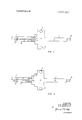
- FIG. 1 is an elevation of an axial tunnel reactor illustrating one embodiment of this invention.
- FIG. 2 is an elevation of another embodiment showing both the installation of the choke and the axial zone and a plurality of interposed zones between the axial zone and the combustion zone.
- FIG. 1 there is shown in general outline a carbon black reactor 1, devoid of its exterior shell and insulation.
- Reactor 1 has axial zone 2, combustion zone 4, and reaction zone 5.
- Hydrocarbon charge oil, or make-oil is injected into axial zone 2 through conduit 6 which is equipped with a discharge nozzle 12.
- Axial zone 2 is also adapted for the introduction of a free oxygen-containing gas thereinto through conduit 7 and for the introduction of combustible gas thereinto through conduit 8, these commingling in section 2.
- oil nozzle 12 is adapted to vary the extent of its extension into zone 2, that is, the extent to which it extends into axial zone 2 is alterable through packing gland I7 exterior of the reactor.
- Combustion zone 4 is equipped with entries 9 which consists of one or more points for the introduction of combustion air and fuel or combustible gases and, if desired, some portion of the charge oil.
- Reactor section 5 is adapted with outlet 16 through which the carbon black produced in section 5 is removed from the reactor.
- choke 1 l Positioned within axial tunnel section 2 is choke 1 l which is formed, for example, of a cylinder positioned with its outer wall adjacent to the interior wall of the axial zone 2. Passageway 15 through choke i1 is large enough to accommodate the withdrawal of nozzle 12 therethrough. Reactants introduced from conduits 7 and 8 in axial section 2 pass through passageway 15 of choke 11, their velocities being increased due to the smaller flow area of passageway 15. Choke 1! can be positioned anywhere along wall 10 of axial zone 2.
- Stepped zone 3 has a substantially constant diameter which is greater than that of axial zone 2 but less than the diameter of combustion zone 4.
- the reactor can be operated so that the reactants introduced into axial zone 2 are accelerated in velocity while passing through passageway 15 of choke l1 proximate the discharge of charge oil from nozzle 12 to form a reactant mass which is subsequently expanded into stepped zone 3 and is again expanded into combustion zone 4, into which an additional portion of the reactants are introduced through entries 9.
- Both choke l5 and nozzle 12 are adjusted independently of each other along the length of axial tunnel 2.
- Choke 11 is adapted for adjustment in location from any position from the inlet wall of axial tunnel 2 to a point within stepped zone 3.
- Charge oil nozzle 12 is similarly adjustable.
- passageway 15 of choke 11 is made other than cylindrical, for example the configuration of a truncated cone, the gases can be directed angularly across the discharge from nozzle 12.
- FIG. 2 illustrates another embodiment of the invention in which like numbers are used to designate like parts with reference to FIG. 1.
- a second stepped zone 30 is interposed between first stepped zone 3 and combustion zone 4. ln other words, there is imparted to the gases after exiting axial tunnel 2, two expansions, one into stepped zone 3 and one into stepped zone 30 prior to their introduction into zone 4.
- the apparatus of subject invention permits wider range of the reactor operability in a process which affects the carbon black product quality and the yield of carbon black produced from the process.
- a second run was made in a conventional axial tunnel reactor having an axial zone of 13 inches diameter, a combustion chamber having a diameter of 37 inches and a reaction zone having a diameter of 10 inches. This is shown in the data below as a 13 inches X 10 inches reactor.
- a third run was made practicing the method of this invention in apparatus of this invention, that is, in apparatus having an axial zone of 13 inches diameter, the axial zone having a choke positioned therein, the choke having a passageway diameter of 12 inches, an interposed stepped zone of 17 inches diameter, a combustion zone of 37 inches diameter and a reaction zone having a 10-inch diameter. This is shown in the data below as 13 inches 12 inches X 17 inches X 10 inches reactor.
- oil nozzle location indicates the position of the hydrocarbon nozzle within the axial section, in inches, measured from the inlet of the combustion section, in a direction upstream into the axial section, to the discharge apertures of the nozzle.
- EXAMPLE II A second series of runs was made.
- Run 4 a stepped, unchoked reactor having an axial zone of 15 inches diameter, a stepped zone of 17 inches diameter and 3 inches length, and a reaction zone of 10 inches diameter was employed, that is, a reactor size 15 inches X 17 inches X 10 inches.
- a choked and stepped reactor size 13 inches l2 inches X 17 inches X 10 inches, was employed, this reactor being a reactor of the same size as that used in Run 3 of example 1.
- the length of the l7-inches diameter stepped zone was 3 inches.
- the choke was 4% inches long, and the passageway through the choke was cylindrical and of uniform diameter throughout its length. in all instances the choke was positioned with its downstream edge coinciding with the upstream edge of the first stepped zone.
- the total length of the axial stepped tunnel was 45 inches, including the length of the stepped zone which was 3 inches.
- combustion zone in all reactors was 12 inches long and 37 inches in diameter. Reaction zone diameters and lengths were as indicated in the various data.
- chokes of any lengths may be employed.
- any passageway configuration can be employed although it is preferable that the passageway be of cylindrical configuration or of a configuration which decreases in area in the direction of flow therethrough.
- the men of the potngewuy through the choke can vary from about 0.0-1 to about 0.80 that of the area of the unrestricted axial section, preferably from about 0.25 to about 0.65 that of the area of the unrestricted axial section.
- the choke can be positioned at any point along the length of the axial section, or at any point in relation to the discharge nozzle of the charge oil introductory line, it only being preferable that some unrestricted area of the axial section be provided upstream of the choke for the introduction of at least a portion of the reactants thereinto, and from which such reactants have their velocities increased as they pass through the choke.
- stepped zones may be of any length,'-lengths of from about l inch to about 30 inchesypreferably'fromabout 3 inches to about 20 inches having been found preferable.
- the stepped zones may be of any diameter intermediate the diameter of the axial zone and the diameter of the combustion zone. If more than a single stepped zone is supplied, the zones are arranged in the order of increasing diameter in the direction of flow from the axial section to the combustion section.
- a process for the production of carbon black by the pyrolytic decomposition of a hydrocarbon feed by contacting said hydrocarbon feed with hot combustion gases produced by the oxidation of a combustible gas with a free oxygen-containing gas which comprises:
- a carbon black reactor which comprises:
- a combustion section in axial contiguous alignment with said stepped section, said combustion section having a diameter greater than the diameter of said stepped section and being adapted with conduit means through its periphery for the introduction of reactants thereinto;
- reaction section in axial alignment with said combustion section and adapted with conduit means for recovery of carbon black.
- the passageway through said choke has an area from about 0.04 to about 0.8 of the area of said axial section.
Landscapes
- Chemical & Material Sciences (AREA)
- Organic Chemistry (AREA)
- Pigments, Carbon Blacks, Or Wood Stains (AREA)
Abstract
Process and apparatus for the production of carbon black wherein an oxygen-containing gas, with or without fuel, is introduced into an axial zone of a reactor and passed through a diametrally restricted section of said zone wherein it is commingled with hydrocarbon feed, the mixture passed into at least one stepped zone having a cross-sectional area greater than the crosssectional area of said axial zone wherein it is expanded, the expanded mixture passed into a combustion zone and contacted therein with combustion gases, and the resulting mass passed into a reaction zone wherein the hydrocarbon feed is pyrolytically decomposed into carbon black.
Description
' United States Patent Inventors Eulas W. Henderson Robert E. Dollinger, Phillips, both of Tex. Appl. No. 731,522 Filed May 23, 1968 Patented Sept. 21, 1971 Assignee Phillips Petroleum Company CARBON BLACK PROCESS AND REACTOR 9 Claims, 2 Drawing Figs. 05. Cl. 23/2094, 23/2595 Int. Cl. C09c 1/50 Field of Search 23/2094, 209.6, 259.5; 260/679; 23/277 References Cited UNITED STATES PATENTS 2,682,450 6/1954 Sweigart et al. 23/2595 2,790,838 4/1957 Schrader 260/679 Primary Examiner-Edward J. Meros Attorney-Young and Quigg ABSTRACT: Process and apparatus for the production of carbon black wherein an oxygen-containing gas, with or without fuel, is introduced into an axial zone of a reactor and passed through a diametrally restricted section of said zone wherein it is commingled with hydrocarbon feed, the mixture passed into at least one stepped zone having a cross-sectional area greater than the cross-sectional area of said axial zone wherein it is expanded, the expanded mixture passed into a combustion zone and contacted therein with combustion gases, and the resulting mass passed into a reaction zone wherein the hydrocarbon feed is pyrolytically decomposed into carbon black.
PATENTEU SEP21 197i 3507057 INVENTORS E W. HENDERSON R E. DOLLINGER A TTORNEVS CARBON BLACK PROCESS AND REACTOR This invention refers to a process and to apparatus for producing carbon black. In one of its more specific aspects, it refers to an improved process and apparatus for the production of carbon black. Carbon black, which is widely used in rubber production, is required by industrial users in a wide rangof product specifications. For various reasons, onlya comparatively small proportion of the carbon blacks for which specifications have been developed can be produced in any one reactor. Accordingly, efforts have been made to develop a reactor which would produce a wide range of carbon black products.
There has now been developed a carbon black process and a carbon black reactor for producing a wider range of carbon black products. According to the process of this invention, there is provided a method for producing carbon black by the pyrolytic decomposition of a hydrocarbon which comprises introducing a hydrocarbon feedstock and free oxygen-containing gas and combustible gases into a first zone, passing said reactants through a zone proximate the discharge of the charge oil nozzle at high velocities to form a reactant mixture, expanding the reactants into a second zone, and passing the reactants into a third zone into which a quantity of combustion gases are introduced to form a reactant mass, and passing the reactant mass into a fourth zone where at least a portion of the carbonaceous material is pyrolytically decomposed to form carbon black.
There has also been invented a reactor for the practice of this invention, this reactor comprising a multitude of axially aligned, contiguous reaction zones, the first reaction zone adapted for the introduction of the reactants, the first reaction zone having a choke or restriction positioned therein to form a passageway of decreased cross-sectional area therein, said passageway being adapted to permit the projection of the charge oil nozzle therethrough and to direct the passage of reactants therethrough proximate the oil discharge nozzle, a second reaction zone in open communication with the first reaction zone, the second zone having a diameter greater than the diameter of the first reaction zone, the third reaction zone in open communication with the second reaction zone and having a diameter greater than the diameter of the second reaction zone, said third reaction zone being adapted for the introduction of additional reactants, a fourth reaction zone in open communication with the third reaction zone, the fourth reaction zone being adapted for the recovery of carbon black therefrom.
Accordingly, it is an object of this invention to provide an improved process for producing carbon black.
It is another object of this invention to provide an improved reactor for producing carbon black.
These, and other objects, will become more fully apparent from the following discussion.
In one of the conventional prior art processes, carbon black is produced by introducing a portion of the reactants into the first, or axial zone, expanding these reactants into a second zone into which a second portion of the reactants is introduced and conducting the reaction mass thus formed into a third zone where the principal portion of the carbon black is produced and from which the carbon black produced is removed. In this reactor in which this prior art process is conducted, these zones exist in axial, contiguous relationship and the second, or combustion, zone has a diameter greater than the diameter of the axial zone.
It has now been discovered that if this reactor is modified to the extent of providing a choke or restriction in the axial zone and, in addition, to the extent of interposing at least one zone of intermediate, substantially constant, diameter between the axial zone and combustion zone, a wider range of carbon blacks can be produced in the same reactor.
Various embodiments of the process and of the reactor exist. One of these consists of a choke having a cylindrical passageway therethrough, the choke being movably positionable along the length of the axial zone to the extent of extending into at least a portion of the zone interposed between the axial zone and combustion zone. This interposed zone will be referred to as the stepped zone, the effect of its interposition into the reactor being to produce a reactor having an axially stepped tunnel.
In another embodiment of this invention, the passageway of the choke is of variable diameter through its length, that is, the diameter of the passageway varies along its length through the choke.
In another embodiment of this invention, there are interposed between the axial zone and the combustion zone a plurality of stepped zones each of which has a substantially constant diameter greater than the diameter of the axial zone but less than the diameter of the combustion zone, the diameter of the individual stepped zones increasing in the direction from the axial zone to the combustion zone, that is, in the direction of the flow of the hydrocarbon reactants through the reactor.
In order to facilitate an understanding of this invention, reference is made to the attached drawings which show two embodiments of this invention.
FIG. 1 is an elevation of an axial tunnel reactor illustrating one embodiment of this invention.
FIG. 2 is an elevation of another embodiment showing both the installation of the choke and the axial zone and a plurality of interposed zones between the axial zone and the combustion zone.
Referring now to FIG. 1, there is shown in general outline a carbon black reactor 1, devoid of its exterior shell and insulation. Reactor 1 has axial zone 2, combustion zone 4, and reaction zone 5. Hydrocarbon charge oil, or make-oil, is injected into axial zone 2 through conduit 6 which is equipped with a discharge nozzle 12. Axial zone 2 is also adapted for the introduction of a free oxygen-containing gas thereinto through conduit 7 and for the introduction of combustible gas thereinto through conduit 8, these commingling in section 2. It will be noted that oil nozzle 12 is adapted to vary the extent of its extension into zone 2, that is, the extent to which it extends into axial zone 2 is alterable through packing gland I7 exterior of the reactor.
Positioned within axial tunnel section 2 is choke 1 l which is formed, for example, of a cylinder positioned with its outer wall adjacent to the interior wall of the axial zone 2. Passageway 15 through choke i1 is large enough to accommodate the withdrawal of nozzle 12 therethrough. Reactants introduced from conduits 7 and 8 in axial section 2 pass through passageway 15 of choke 11, their velocities being increased due to the smaller flow area of passageway 15. Choke 1! can be positioned anywhere along wall 10 of axial zone 2.
Interposed between zone 2 and zone 4 is stepped zone 3. Stepped zone 3 has a substantially constant diameter which is greater than that of axial zone 2 but less than the diameter of combustion zone 4.
It will be seen that the reactor can be operated so that the reactants introduced into axial zone 2 are accelerated in velocity while passing through passageway 15 of choke l1 proximate the discharge of charge oil from nozzle 12 to form a reactant mass which is subsequently expanded into stepped zone 3 and is again expanded into combustion zone 4, into which an additional portion of the reactants are introduced through entries 9. Both choke l5 and nozzle 12 are adjusted independently of each other along the length of axial tunnel 2. Choke 11 is adapted for adjustment in location from any position from the inlet wall of axial tunnel 2 to a point within stepped zone 3. Charge oil nozzle 12 is similarly adjustable.
It will be appreciated that a considerable increase in velocity is imparted to that mixture of gas passing through the passageway 15 of choke 11 as compared to that velocity of the gases through the unrestricted portion of axial tunnel 2.
It will be further appreciated that by varying the configuration of the passageway through choke 11, a considerable change in direction can be effected to the flow of the gases through passagewayand that, depending upon the amount of gases introduced into axial section 2, either turbulent or laminar flow thereto can be effected by adjustment of the diameter of passageway 15 through choke 11. Due to the length of choke 11 in relation to the length of the axial tunnel 2, it is preferable that choke 11 be positionable to encompass noule 12 at its most withdrawn position from combustion chamber 4.
It will befurther appreciated that if the configuration of passageway 15 of choke 11 is made other than cylindrical, for example the configuration of a truncated cone, the gases can be directed angularly across the discharge from nozzle 12.
FIG. 2 illustrates another embodiment of the invention in which like numbers are used to designate like parts with reference to FIG. 1.
The prior description is generally applicable to the embodiment shown in FIG. 2; however, in this embodiment, a second stepped zone 30 is interposed between first stepped zone 3 and combustion zone 4. ln other words, there is imparted to the gases after exiting axial tunnel 2, two expansions, one into stepped zone 3 and one into stepped zone 30 prior to their introduction into zone 4.
It will be appreciated that while but two stepped zones are shown in this figure, a larger number of stepped zones can be employed.
The modifications previously mentioned in reference to FIG. 1 are also applicable to FIG. 2.
As previously mentioned, the apparatus of subject invention permits wider range of the reactor operability in a process which affects the carbon black product quality and the yield of carbon black produced from the process. These afi'ects are shown in the following examples.
EXAMPLE I The carbon black reactor of the previous description was operated in the process of this invention, under conditions indicated below.
Three individual runs were made, one in a conventional axial tunnel reactor having an axial zone of 12 inches diameter, a combustion chamber or zone having a diameter of 37 inches and a reaction zone having a diameter of 10 inches. These results are shown in the data below as 12 inches x 10 inches reactor.
A second run was made in a conventional axial tunnel reactor having an axial zone of 13 inches diameter, a combustion chamber having a diameter of 37 inches and a reaction zone having a diameter of 10 inches. This is shown in the data below as a 13 inches X 10 inches reactor.
A third run was made practicing the method of this invention in apparatus of this invention, that is, in apparatus having an axial zone of 13 inches diameter, the axial zone having a choke positioned therein, the choke having a passageway diameter of 12 inches, an interposed stepped zone of 17 inches diameter, a combustion zone of 37 inches diameter and a reaction zone having a 10-inch diameter. This is shown in the data below as 13 inches 12 inches X 17 inches X 10 inches reactor.
Data were as follows:
Axial Gas, Mscfh TABLE l-Continued Run No. l 2 I 3 Reactor Type Axial Axial Axial Choked Stepped Combustion Air, Mscl'h 185 185 14.2 Combustion Gas, Mscfh 14.2 14.0 12.2 Air/Oil Rate, s.c.f./gal. 61 l 657 587 Reactor Length. In. 88 65 96 Yield, '1 C. to Black 50.3 48.6 50.4 Product Quality Photolometer. Z 91 95 93 NQSA, m3/g. 86 97 87 DBP, cc./l00g. 144 147 149 in the above data, and in the data to follow, oil nozzle location indicates the position of the hydrocarbon nozzle within the axial section, in inches, measured from the inlet of the combustion section, in a direction upstream into the axial section, to the discharge apertures of the nozzle.
These data indicate the operability of the process of this invention to produce a black which, at comparable photolometer values, possess a surface area comparable to that black produced in the conventional axial reactor, not withstanding the lower air to oil ratio employed. While the data do not indicate that axial gas was introduced into the axial zone, it is evident that such introduction could have been made.
EXAMPLE II A second series of runs was made. in Run 4, a stepped, unchoked reactor having an axial zone of 15 inches diameter, a stepped zone of 17 inches diameter and 3 inches length, and a reaction zone of 10 inches diameter was employed, that is, a reactor size 15 inches X 17 inches X 10 inches. In comparison a choked and stepped reactor, size 13 inches l2 inches X 17 inches X 10 inches, was employed, this reactor being a reactor of the same size as that used in Run 3 of example 1. The length of the l7-inches diameter stepped zone was 3 inches.
These data indicate that when producing carbon black of the same photolometer value, this invention, when practiced in a smaller reactor, at comparable charge oil rates, produces a higher surface area black.
A comparison of Run 5, above, with Run 3 of table I indicates that within the same axial stepped choked reactor, carbon blacks of widely different properties can be produced.
5 EXAMPLE [II An additional run was made in the reactor employed in Run 5, for the purpose of increasing the distance from the nozzle location to the combustion zone to 18 inches, while simultaneously increasing reactor length but decreasing the air to oil ratio to prevent after treating, in order to indicate the wide operability of the process and produce a lower surface area black. Resultswere asfollow s:
Axial Gas, Mscfh Combustion Air, Mscl'h I85 Combustion Gas, Mscfh 14.2 Combustion Oxygen, Mscl'h 3.7 Air/Oil Rate, s.c.f.lgal. 612 Reactor Length, in. 94 Yield. k C. to Black 51.2 Product Quality Photolometer, k 85 DBP, ccJlOOg. 142
These data indicate the wide range of operability of the process and apparatus of this invention, particularly in respect to the oil nozzle location, length of reactor, air-oil ratio, performance with axial air as the only reactant other than oil being introduced into the axial zone, the introduction of oxygen into the combustion zone as well as high conversion and the low surface area black produced.
in the above runs in which an axial stepped chocked reactor was used, the choke was 4% inches long, and the passageway through the choke was cylindrical and of uniform diameter throughout its length. in all instances the choke was positioned with its downstream edge coinciding with the upstream edge of the first stepped zone. The total length of the axial stepped tunnel was 45 inches, including the length of the stepped zone which was 3 inches.
Similarly, the combustion zone in all reactors was 12 inches long and 37 inches in diameter. Reaction zone diameters and lengths were as indicated in the various data.
However, it is not intended that the invention be limited to reactors possessing these dimensions since choke characteristics and stepped zone characteristics, in addition to those delineated above are known to be suitable. For example, chokes of any lengths may be employed. Generally, it is only desirable that the choke be shorter in length than the length of the axial tunnel, and of suitable length to direct the flow of gases therethrough along an established path of flow. Chokes generally having a length of about 4 to about 8 inches are satisfactory.
Similarly, any passageway configuration can be employed although it is preferable that the passageway be of cylindrical configuration or of a configuration which decreases in area in the direction of flow therethrough.
The men of the puimngewuy through the choke can vary from about 0.0-1 to about 0.80 that of the area of the unrestricted axial section, preferably from about 0.25 to about 0.65 that of the area of the unrestricted axial section.
Similarly, the choke can be positioned at any point along the length of the axial section, or at any point in relation to the discharge nozzle of the charge oil introductory line, it only being preferable that some unrestricted area of the axial section be provided upstream of the choke for the introduction of at least a portion of the reactants thereinto, and from which such reactants have their velocities increased as they pass through the choke.
Any number of stepped zones of any diameter and of any length have been found effective. While the above runs were conducted in reactors having a single stepped zone, any
number of stepped zones may be'employed. Similarly, the
stepped zones may be of any length,'-lengths of from about l inch to about 30 inchesypreferably'fromabout 3 inches to about 20 inches having been found preferable.
Also, the stepped zones may be of any diameter intermediate the diameter of the axial zone and the diameter of the combustion zone. If more than a single stepped zone is supplied, the zones are arranged in the order of increasing diameter in the direction of flow from the axial section to the combustion section.
While the method and apparatus of this invention have been described and explained in relation to certain embodiments, the invention is not meant to be limited thereto but is intended to be inclusive of reasonable variations thereof.
What is claimed is:
l. A process for the production of carbon black by the pyrolytic decomposition of a hydrocarbon feed by contacting said hydrocarbon feed with hot combustion gases produced by the oxidation of a combustible gas with a free oxygen-containing gas which comprises:
a. introducing a free oxygen-containing gas into a first section of an axial zone of a carbon black reactor;
b. introducing hydrocarbon feed downstream of the locus of introduction of said free oxygen-containing gas into a diametrally restricted portion of said axial zone, said portion of said axial zone having a cross-sectional area less than the cross-sectional area of said first section;
c. passing said first free oxygen-containing gas through said first section at a first velocity;
(1. passing said oxygen-containing gas through said diametrally restricted portion of said axial zone and into contact with said hydrocarbon feed at a velocity greater than said first velocity forming a reactant mass;
e. passing said reactant mass into at least one stepped zone having a cross-sectional area greater than the cross-sectional area of said axial zone wherein said mass is expanded;
. passing the expanded reactant mass into a combustion zone having a diameter greater than said zone and into contact with combustion gases introduced through the periphery of said combustion zone under conditions to form carbon black;
g. passing the reactant mass into a reaction zone wherein carbon black is formed; and,
h. recovering the carbon black.
2. The process as defined in claim 1, wherein the hydrocarbon feed is introduced into the axial zone upstream of the diametrally restricted section.
3. The process as defined in claim 1 in which the reactant mass from the axial section is expanded by passage into a plurality of stepped zones contiguously positioned between said axial section and said combustion section, each of said stepped sections being of substantially uniform diameter and having a greater diameter than the intermediate preceding stepped section.
4. The process as defined in claim 3 in which said first gas is accelerated in passing through said restricted portion of the axial zone to a velocity of 1.04 to about l.8 times said first velocity.
5. The process as defined in claim 3 in which the rcuctunt mass is expanded three times in successively positioned stepped zones.
6. A carbon black reactor which comprises:
a. an axial section adapted with conduit means for the introduction of hydrocarbon feed and gaseous reactants;
b. a choke positioned within said axial section;
c. at least one stepped section in axial contiguous alignment with said axial section, said stepped section having a substantially unifonn diameter greater than me diameter of said axial section;
. a combustion section in axial contiguous alignment with said stepped section, said combustion section having a diameter greater than the diameter of said stepped section and being adapted with conduit means through its periphery for the introduction of reactants thereinto; and
. a reaction section in axial alignment with said combustion section and adapted with conduit means for recovery of carbon black.
the passageway through said choke has an area from about 0.04 to about 0.8 of the area of said axial section.
UNITED STATES PATENT OFFICE CERTIFICATE OF CORRECTION ient N00 3,507,057 Eulas W. Henderson et a1 Dated: September 21, 1971 It is certified that error appears in the above-identified patent and that said :tters Patent are hereby corrected as shown below:
Claim 1, column 6, line &6, after "said" insert stepped Signed and sealed this 7th day of March 1972.
EAL)
test:
22H? M.FLETQHER,JR. ROBERT GOI'TSCHALK s 1mg Offlcer Commissioner of Patents
Claims (8)
- 2. The process as defined in claim 1, wherein the hydrocarbon feed is introduced into the axial zone upstream of the diametrally restricted section.
- 3. The process as defined in claim 1 in which the reactant mass from the axial section is expanded by passage into a plurality of stepped zones contiguously positioned between said axial section and said combustion section, each of said stepped sections being of substantially uniform diameter and having a greater diameter than the intermediate preceding stepped section.
- 4. The process as defined in claim 3 in which said first gas is accelerated in passing through said restricted portion of the axial zone to a velocity of 1.04 to about 1.8 times said first velocity.
- 5. The process as defined in claim 3 in which the reactant mass is expanded three times in successively positioned stepped zones.
- 6. A carbon black reactor which comprises: a. an axial section adapted with conduit means for the introduction of hydrocarbon feed and gaseous reactants; b. a choke positioned within said axial section; c. at least one stepped section in axial contiguous alignment with said axial section, said stepped section having a substantially uniform diameter greater than the diameter of said axial section; d. a combustion section in axial contiguous alignment with said stepped section, said combustion section having a diameter greater than the diameter of said stepped section and being adapted with conduit means through its periphery for the introduction of reactants thereinto; and e. a reaction section in axial alignment with said combustion section and adapted with conduit means for recovery of carbon black.
- 7. The carbon black reactor as defined in claim 6 in which said choke is movably positioned within said axial section.
- 8. The carbon black reactor as defined in claim 7 in which said choke is positioned within said axial section downstream from the locus of discharge of said conduit means for the introduction of hydrocarbon feed and gaseous reactants.
- 9. The carbon black reactor as defined in claim 8 in which the passageway through said choke has an area from about 0.04 to about 0.8 of the area of said axial section.
Applications Claiming Priority (1)
| Application Number | Priority Date | Filing Date | Title |
|---|---|---|---|
| US73152268A | 1968-05-23 | 1968-05-23 |
Publications (1)
| Publication Number | Publication Date |
|---|---|
| US3607057A true US3607057A (en) | 1971-09-21 |
Family
ID=24939879
Family Applications (1)
| Application Number | Title | Priority Date | Filing Date |
|---|---|---|---|
| US731522A Expired - Lifetime US3607057A (en) | 1968-05-23 | 1968-05-23 | Carbon black process and reactor |
Country Status (11)
| Country | Link |
|---|---|
| US (1) | US3607057A (en) |
| BE (1) | BE733444A (en) |
| BR (1) | BR6908876D0 (en) |
| DE (1) | DE1926114A1 (en) |
| ES (1) | ES366882A1 (en) |
| FR (1) | FR2009212A1 (en) |
| GB (1) | GB1271327A (en) |
| LU (1) | LU58704A1 (en) |
| MY (1) | MY7300257A (en) |
| NL (1) | NL6907861A (en) |
| SE (1) | SE345282B (en) |
Cited By (4)
| Publication number | Priority date | Publication date | Assignee | Title |
|---|---|---|---|---|
| US3989804A (en) * | 1972-09-07 | 1976-11-02 | Phillips Petroleum Company | Carbon black method |
| US4085197A (en) * | 1974-04-29 | 1978-04-18 | Phillips Petroleum Company | Carbon black process |
| US4094960A (en) * | 1976-03-04 | 1978-06-13 | Phillips Petroleum Company | Process for production of carbon black |
| US5252297A (en) * | 1990-11-13 | 1993-10-12 | Tokai Carbon Co., Ltd. | Process for producing carbon black and apparatus therefor |
Citations (8)
| Publication number | Priority date | Publication date | Assignee | Title |
|---|---|---|---|---|
| US2682450A (en) * | 1950-11-27 | 1954-06-29 | United Carbon Company Inc | Apparatus for producing carbon black |
| US2790838A (en) * | 1952-01-16 | 1957-04-30 | Eastman Kodak Co | Process for pyrolysis of hydrocarbons |
| US3079236A (en) * | 1960-08-12 | 1963-02-26 | Columbian Carbon | Manufacture of carbon black |
| US3220803A (en) * | 1959-07-08 | 1965-11-30 | Montedison Spa | Process and apparatus for modifying and determining the optimum volume of the operating reaction chamber in ovens employed for the production of acetylene from hydrocarbons |
| US3256065A (en) * | 1962-10-30 | 1966-06-14 | Continental Carbon Co | Apparatus for making carbon black |
| US3355247A (en) * | 1964-05-25 | 1967-11-28 | Phillips Petroleum Co | Production of high structure furnace carbon black |
| US3375075A (en) * | 1964-11-03 | 1968-03-26 | Continental Carbon Co | Method and apparatus for producing carbon black |
| US3420632A (en) * | 1966-11-18 | 1969-01-07 | Phillips Petroleum Co | Production of carbon black using plasma-heated nitrogen |
-
1968
- 1968-05-23 US US731522A patent/US3607057A/en not_active Expired - Lifetime
-
1969
- 1969-05-07 ES ES366882A patent/ES366882A1/en not_active Expired
- 1969-05-16 BR BR208876/69A patent/BR6908876D0/en unknown
- 1969-05-22 SE SE7244/69A patent/SE345282B/xx unknown
- 1969-05-22 NL NL6907861A patent/NL6907861A/xx unknown
- 1969-05-22 BE BE733444D patent/BE733444A/xx unknown
- 1969-05-22 GB GB26229/69A patent/GB1271327A/en not_active Expired
- 1969-05-22 LU LU58704D patent/LU58704A1/xx unknown
- 1969-05-22 DE DE19691926114 patent/DE1926114A1/en active Pending
- 1969-05-23 FR FR6917016A patent/FR2009212A1/fr not_active Withdrawn
-
1973
- 1973-12-31 MY MY1973257A patent/MY7300257A/en unknown
Patent Citations (8)
| Publication number | Priority date | Publication date | Assignee | Title |
|---|---|---|---|---|
| US2682450A (en) * | 1950-11-27 | 1954-06-29 | United Carbon Company Inc | Apparatus for producing carbon black |
| US2790838A (en) * | 1952-01-16 | 1957-04-30 | Eastman Kodak Co | Process for pyrolysis of hydrocarbons |
| US3220803A (en) * | 1959-07-08 | 1965-11-30 | Montedison Spa | Process and apparatus for modifying and determining the optimum volume of the operating reaction chamber in ovens employed for the production of acetylene from hydrocarbons |
| US3079236A (en) * | 1960-08-12 | 1963-02-26 | Columbian Carbon | Manufacture of carbon black |
| US3256065A (en) * | 1962-10-30 | 1966-06-14 | Continental Carbon Co | Apparatus for making carbon black |
| US3355247A (en) * | 1964-05-25 | 1967-11-28 | Phillips Petroleum Co | Production of high structure furnace carbon black |
| US3375075A (en) * | 1964-11-03 | 1968-03-26 | Continental Carbon Co | Method and apparatus for producing carbon black |
| US3420632A (en) * | 1966-11-18 | 1969-01-07 | Phillips Petroleum Co | Production of carbon black using plasma-heated nitrogen |
Cited By (4)
| Publication number | Priority date | Publication date | Assignee | Title |
|---|---|---|---|---|
| US3989804A (en) * | 1972-09-07 | 1976-11-02 | Phillips Petroleum Company | Carbon black method |
| US4085197A (en) * | 1974-04-29 | 1978-04-18 | Phillips Petroleum Company | Carbon black process |
| US4094960A (en) * | 1976-03-04 | 1978-06-13 | Phillips Petroleum Company | Process for production of carbon black |
| US5252297A (en) * | 1990-11-13 | 1993-10-12 | Tokai Carbon Co., Ltd. | Process for producing carbon black and apparatus therefor |
Also Published As
| Publication number | Publication date |
|---|---|
| GB1271327A (en) | 1972-04-19 |
| ES366882A1 (en) | 1971-04-01 |
| BR6908876D0 (en) | 1973-01-11 |
| MY7300257A (en) | 1973-12-31 |
| BE733444A (en) | 1969-11-24 |
| FR2009212A1 (en) | 1970-01-30 |
| NL6907861A (en) | 1969-11-25 |
| LU58704A1 (en) | 1970-01-14 |
| DE1926114A1 (en) | 1969-11-27 |
| SE345282B (en) | 1972-05-23 |
Similar Documents
| Publication | Publication Date | Title |
|---|---|---|
| US3619138A (en) | Carbon-black process | |
| US2851337A (en) | Carbon black process | |
| EP0494068B1 (en) | Method and apparatus for producing carbon black | |
| US3753658A (en) | Carbon black apparatus | |
| US3567395A (en) | Apparatus for producing carbon black | |
| CA1300343C (en) | Apparatus and process for producing carbon black | |
| EP0360399B1 (en) | Axial reactor with coaxial oil injection | |
| US3701827A (en) | Process and apparatus for the production of large particle-size,low structure carbon black | |
| US4447401A (en) | Carbon black reactor with angled combustion chamber and non-aligned tangential hot gas entries for production of negative tint residual carbon black | |
| US3607057A (en) | Carbon black process and reactor | |
| US4093421A (en) | Apparatus for producing carbon black | |
| US3867513A (en) | Method for producing carbon black | |
| US4339422A (en) | Carbon black manufacture | |
| US3523759A (en) | Apparatus for producing carbon black | |
| US3410660A (en) | Carbon black reactor and method of making carbon black | |
| US3726964A (en) | Process for the production of carbon black | |
| US3681031A (en) | Carbon black reactor | |
| US2781250A (en) | Carbon black reactor | |
| US4360497A (en) | Feedstock nozzle and use in carbon black reactor | |
| US3409406A (en) | Apparatus for the production of carbon black | |
| US3619141A (en) | Carbon black production | |
| US3592596A (en) | Method and apparatus for the production of carbon black | |
| US3592597A (en) | Carbon black process and reactor | |
| US3645685A (en) | Carbon black manufacture | |
| US4486398A (en) | Feedstock nozzle for low tint residual carbon black |