US3604697A - Hood and ladle assembly for collecting dust powders during pouring of a molten material - Google Patents
Hood and ladle assembly for collecting dust powders during pouring of a molten material Download PDFInfo
- Publication number
- US3604697A US3604697A US744084A US3604697DA US3604697A US 3604697 A US3604697 A US 3604697A US 744084 A US744084 A US 744084A US 3604697D A US3604697D A US 3604697DA US 3604697 A US3604697 A US 3604697A
- Authority
- US
- United States
- Prior art keywords
- ladle
- hood
- dust
- molten material
- pig iron
- Prior art date
- Legal status (The legal status is an assumption and is not a legal conclusion. Google has not performed a legal analysis and makes no representation as to the accuracy of the status listed.)
- Expired - Lifetime
Links
- 239000000428 dust Substances 0.000 title claims abstract description 42
- 239000000843 powder Substances 0.000 title claims abstract description 40
- 239000012768 molten material Substances 0.000 title claims description 16
- 229910000805 Pig iron Inorganic materials 0.000 claims abstract description 24
- 230000000295 complement effect Effects 0.000 claims description 4
- 230000013011 mating Effects 0.000 claims description 2
- XEEYBQQBJWHFJM-UHFFFAOYSA-N Iron Chemical compound [Fe] XEEYBQQBJWHFJM-UHFFFAOYSA-N 0.000 description 4
- 229910052742 iron Inorganic materials 0.000 description 2
- 238000007599 discharging Methods 0.000 description 1
- 239000000463 material Substances 0.000 description 1
- 239000011819 refractory material Substances 0.000 description 1
Images


Classifications
-
- C—CHEMISTRY; METALLURGY
- C21—METALLURGY OF IRON
- C21C—PROCESSING OF PIG-IRON, e.g. REFINING, MANUFACTURE OF WROUGHT-IRON OR STEEL; TREATMENT IN MOLTEN STATE OF FERROUS ALLOYS
- C21C5/00—Manufacture of carbon-steel, e.g. plain mild steel, medium carbon steel or cast steel or stainless steel
- C21C5/28—Manufacture of steel in the converter
- C21C5/38—Removal of waste gases or dust
- C21C5/40—Offtakes or separating apparatus for converter waste gases or dust
-
- C—CHEMISTRY; METALLURGY
- C21—METALLURGY OF IRON
- C21C—PROCESSING OF PIG-IRON, e.g. REFINING, MANUFACTURE OF WROUGHT-IRON OR STEEL; TREATMENT IN MOLTEN STATE OF FERROUS ALLOYS
- C21C5/00—Manufacture of carbon-steel, e.g. plain mild steel, medium carbon steel or cast steel or stainless steel
- C21C5/28—Manufacture of steel in the converter
- C21C5/42—Constructional features of converters
- C21C5/46—Details or accessories
- C21C5/466—Charging device for converters
-
- C—CHEMISTRY; METALLURGY
- C21—METALLURGY OF IRON
- C21C—PROCESSING OF PIG-IRON, e.g. REFINING, MANUFACTURE OF WROUGHT-IRON OR STEEL; TREATMENT IN MOLTEN STATE OF FERROUS ALLOYS
- C21C1/00—Refining of pig-iron; Cast iron
- C21C1/06—Constructional features of mixers for pig-iron
Definitions
- the hood assembly is also provided with a [56] References cued dust outlet which registers with an exhaust duct when the hood assembly 15 moved into position atop the ladle whereby UNITED STATES PATENTS dust powder produced during the pouring is vented through 2,923,227 2/ 1960 Hawley 98/115 7 the exhaust duct and collected s, Q r. 2 2
- the area of the opening of the pit is so large that the lid becomes large in size and is liable to undergo thermal deformation.
- the rotatable or horizontally slidable lid makes the apparatus considerably large in size.
- the rotatable or horizontally slidable lid when displaced to open the pit, occupies a considerably large space and hence obstructs the operations to be carried out in the space near the pit and interferes with the neighboring apparatus.
- the principal object of the invention is to obviate the above-mentioned disadvantages.
- an improved dust-collecting apparatus comprises a movable hood for collecting the dust powders and adapted to be engaged into alignment with a ladle and provided at its sidewall with an outlet adapted to be engaged into alignment with a suction inlet of a suction duct when the hood covering the ladle arrives at each end of the pit and molten pig iron in a vessel transferred from a blast furnace is poured from the vessel through the hood into the ladle, the dust powder produced in the hood being exhausted by suction through the suction duct thus collecting the dust powders in an efficient manner.
- FIG. 1 shows diagrammatically a plan view of an embodiment of a dust-collecting apparatus according to the invention
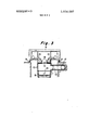
- FIG. 2 is its longitudinal sectional view
- FIG. 3 is a transverse sectional view of a second embodiment, in which provision is made of an air-curtain-producing device;
- FIG. 4 is a perspective view of a hood suspended from a carriage.
- FIG. 5 shows diagrammatically the same sectional view as FIG. 2 for illustrating the operation of the apparatus according to the invention.
- two vessels 1 are rotatably mounted on carriages 2 and adapted to be transferred along rails 3 from a blast furnace (not shown) to each end of a pit 4.
- a ladle 5 is detachably mounted on a carriage 6 and adapted to be moved along rails 7 laid on the bottom of the pit 4.
- a carriage 8 is movable along rails 9 laid on the top wall of the pit 4.
- a hood 10 is suspended from the carriage 8 and provided at its sidewall with a dust powder outlet 11 for discharging dust powders.
- Dust powder exhaust means comprising a suction duct 12 having branch pipes terminated at suction inlets 13 extends through the sidewall of the pit 4 and is adapted to be engaged into alignment or registry with the outlet ll of the hood assembly 10, the branch pipes of the suction duct 12 being provided with dampers 14, respectively.
- FIGS. 1 and 2 show the two vessels 1 rotatably mounted on the carriages 2 and positioned at the left and right ends of the pit 4.
- the ladle 5 which is detachably mounted on the carriage 6 and adapted to be moved along the rails 7.
- FIGS. 1 and 2 show the ladle 5 positioned at the left end of the pit 4 and the vessel 1 at the left side of the pit 4 is inclined so as to pour the molten pig iron contained therein into the ladle 5.
- the hood assembly 10 is provided at its top wall with an opening or passageway 15 through which is passed the molten pig iron.
- the lower end 16 of the sidewall of the hood 10 and the upper end 17 of the sidewall of the ladle 5 are so formed that they are adapted to be moved into engaging alignment with one another.
- the lower end 16 of the sidewall of the hood l0 and the upper end 17 of the sidewall of the ladle 5 include complementary stepped contours which comprise a pair of sloped surfaces capable of effecting and maintaining the lower end 16 of the sidewall of the hood 10 into alignment with the upper end 17 of the ladle 5 in a positive manner.
- the complementary surfaces releasably mate together to maintain the hood and ladle in alignment.
- the hood 10 is brought into engagement with and disengagement from the ladle 5 when the hood 10, which is suspended from the carriage 8, is moved along the rails 9 or when the ladle 5 mounted on the carriage 6 is moved along the rails 7 toward each other.
- the outlet 11 of the hood assembly 10 and the suction inlet 13 of the suction duct 12 are positioned relative to one another to be brought into alignment with one another when the ladle 5 together with the hood I0 is positioned at the left end or right end of the pit 4.
- the carriages 6 and 8 are each provided with wheels adapted to be driven by an electric motor or other driving means.
- the carriage 8 is formed into a gate-shaped framework from which the hood 10 is suspended.
- the inner wall of the hood 10 is protected with refractory material.
- the opening 15 of the hood assembly 10 is provided at its side edges with two protecting cover or guide plates 18 arranged in opposition and inclined from the top wall of the hood 10 so as to effectively enlarge the distance between the top of the cover plates 18.
- the cover plates 18 comprise material guiding surfaces inclined towards the opening or passageway 15 and function to guide the molten material therein.
- a lid (not shown) may be used to close the opening 15 after pouring the molten pig iron therethrough.
- the hood 10 shown in FIG. 4 is provided with the air-curtain-producing device 19.
- the operation of the above-mentioned apparatus will now be explained.
- the ladle 5 is inserted into the pit 4 and placed on the carriage 6 with the aid of a rope 20 suspended from an overhead travelling crane, etc. (not shown).
- the hood assembly 10 together with the carriage 8 is moved until the lower end 16 of the hood 10 is brought into engagement and aligned with the upper end 17 of the ladle 5.
- the assembly is then displaced towards the left end of the pit 4 or towards the right end of the pit 4.
- the outlet 11 of the hood 10 becomes engaged into alignment and registers with the suction inlet 13 of the suction duct 12.
- the molten pig iron in the vessel 1 is then poured through the hood 10 into the ladle 5 while at the same time the dust powder produced in the hood 10 is sucked out through the suction inlet 13 into the suction duct 12.
- the adjustable damper 14 provided at the right side branch of the suction duct 12 is closed so as to suck out the dust powder produced in the hood 10 to a sufficiently strong extent.
- the dampers 14 are adjustable to regulate the exhausting of the dust powders.
- the carriages 6 and 8 are moved in opposite direction to disengage the hood 10 from the ladle 5.
- the ladle containing the molten pig iron is removed out of the pit 4.
- the hood is suspended from the carriage 8 and the ladle 5 is detachably mounted on the carriage 2.
- the hood 10 may be suspended from the overhead travelling crane to omit the carriage 8 and the ladle 5 may be placed stationary on the bottom of the pit 4 to omit the carriage 6.
- the apparatus according to the invention does not always require the provision of the pit and can collect the dust powders in a positive and efficient manner, and results in considerable constructional advantages in that the apparatus is small in size without requiring large space, and hence without giving any hindrance to the neighboring operations and other equipments, and that the above-mentioned disadvantages can be obviated and the apparatus thus provides a considerably efficient and proper dust-collecting apparatus.
- a dust-collecting apparatus for collecting dust powders produced near a movable ladle when molten pig iron is poured from a vessel transferred from a blast furnace into the ladle comprising: a hood provided at its top wall with means defining an opening for passing therethrough molten pig iron and at its sidewall with means defining an outlet for delivering dust powder produced during the pouring of molten pig iron and having means on the lower portion of said sidewall for releasably mating in alignment with the upper end of said ladle; a suction duct positioned to communicate with said outlet of the hood when said hood is positioned on the ladle which occupies a position where the molten pig iron is poured from the vessel through the hood into the ladle; and wherein said hood includes two protecting cover plates positioned in opposition at side edges of said opening and inclined towards said opening to effectively enlarge the distance between the top of the cover plates.
- a dusbcollecting apparatus for collecting dust powder produced during the pouring of molten material into a ladle comprising: a movably mounted ladle movable into and out of a first working position wherein same is in position to receive therein a molten material; a movably mounted hood assembly movable into and out of alignment atop said ladle, said hood assembly having means therein defining a molten material passageway for allowing molten material to be poured therethrough into said ladle when said hood assembly is in alignment therewith, guiding surfaces mounted thereon inclined towards said molten material passageway effective to guide poured molten material into said passageway, and hav-.
- dust powder exhaust means registerable with said dust powder outlet when said ladle is in said first working position for exhausting dust powder from said hood assembly during pouring of the molten material; and means comprising complementary sloped surfaces on said ladle and hood assembly for effecting and maintainin g alignment therebetween.
- said dust powder exhaust means comprises a suction duct having an adjustable damper therein to regulate the exhausting of dust powder' 6.
Landscapes
- Engineering & Computer Science (AREA)
- Chemical & Material Sciences (AREA)
- Manufacturing & Machinery (AREA)
- Materials Engineering (AREA)
- Metallurgy (AREA)
- Organic Chemistry (AREA)
- Environmental & Geological Engineering (AREA)
- Casting Support Devices, Ladles, And Melt Control Thereby (AREA)
- Waste-Gas Treatment And Other Accessory Devices For Furnaces (AREA)
Abstract
A dust collecting apparatus for collecting duct powder produced during the pouring of molten pig iron comprises a ladle for receiving therein the molten pig iron an a hood assembly movable into alignment atop the ladle. The hood assembly has an opening through which the molten pig iron is poured and inclined guiding members are disposed on opposite sides of the opening to guide the flowing molten pig iron into the ladle. The hood assembly is also provided with a dust outlet which registers with an exhaust duct when the hood assembly is moved into position atop the ladle whereby dust powder produced during the pouring is vented through the exhaust duct and collected.
Description
United States Patent [72] lnventors Masashi Kawana; 3,002,739 10/1961 Lawler 266/35 Toshiro Sakai; Takashi Kosukegawa, all of 3,026,102 3/ 1962 McFeaters 266/35 Kurashiki, Japan 3,224,841 12/ 1965 Kemmetmuller 266/35 X [2]] Appl. No. 744,084 3,269,716 8/1966 Walker 266/36 :iled d guly 11141199678l 3,347,539 10/1967 Mitchell et a1... 266/31 X atente ept. 3,472,500 10/1969 Rinesch et al. 266/31 X [73] Assignee Kawasaki Steel Corporation 3,173,489 3/1965 Okaniwa et a1. l. 266/35 X Kobe,.lapan 3,223,397 12/1965 Young 266/34 [32] Priority July 14, 1967 3,358,983 12/1967 Wegscheider 266/31 X [33] Japan Pnmary Exanzmer-J. Spencer Overholser [31 42/45428 Assistant Examiner-John S. Brown AnarneyRobert E. Burns [54] HOOD AND LADLE ASSEMBLY FOR COLLECTING DUST POWDERS DURING ABSTRACT: A dust collectmg apparatus f! collecting duct POURING OF A MOLTEN M ATERI AL powder produced dunng the pouring of molten pig iron com- 6Chims5Drawing Figs prises a ladle for receiving therein the molten pig iron an a hood assembly movable into alignment atop the ladle. The [52] US. Cl 266/31 hood assembly has an opening through which the molten i I] Cl Czlc 5/40 iron is poured and inclined guiding members are disposed on [50] Fleld of Search 266/31, 32, opposite sides of the opening to guide the flowing molten i 36 Rigs/; 122/7 A iron into the ladle. The hood assembly is also provided with a [56] References cued dust outlet which registers with an exhaust duct when the hood assembly 15 moved into position atop the ladle whereby UNITED STATES PATENTS dust powder produced during the pouring is vented through 2,923,227 2/ 1960 Hawley 98/115 7 the exhaust duct and collected s, Q r. 2 2
PATENTEDSEPI 4|en 3.604.697
Such apparatus, however, could not be applied or may be applied with considerable difficulty to the type of pit in which the ladle is moved to each end of the pit where the molten pig iron in the vessel transferred from the blast furnace is poured into the ladle due to the following reasons.
1. The area of the opening of the pit is so large that the lid becomes large in size and is liable to undergo thermal deformation.
2. The rotatable or horizontally slidable lid makes the apparatus considerably large in size.
3. The rotatable or horizontally slidable lid, when displaced to open the pit, occupies a considerably large space and hence obstructs the operations to be carried out in the space near the pit and interferes with the neighboring apparatus.
The principal object of the invention is to obviate the above-mentioned disadvantages.
According to the principles of the present invention, an improved dust-collecting apparatus comprises a movable hood for collecting the dust powders and adapted to be engaged into alignment with a ladle and provided at its sidewall with an outlet adapted to be engaged into alignment with a suction inlet of a suction duct when the hood covering the ladle arrives at each end of the pit and molten pig iron in a vessel transferred from a blast furnace is poured from the vessel through the hood into the ladle, the dust powder produced in the hood being exhausted by suction through the suction duct thus collecting the dust powders in an efficient manner.
Other objects, features and advantages of the invention will become apparent of a consideration from the following specification, when the specification is considered in conjunction with the accompanying drawing, in which:
FIG. 1 shows diagrammatically a plan view of an embodiment of a dust-collecting apparatus according to the invention;
FIG. 2 is its longitudinal sectional view;
FIG. 3 is a transverse sectional view of a second embodiment, in which provision is made of an air-curtain-producing device;
FIG. 4 is a perspective view of a hood suspended from a carriage; and
FIG. 5 shows diagrammatically the same sectional view as FIG. 2 for illustrating the operation of the apparatus according to the invention.
Referring to FIGS. 1 and 2, two vessels 1 are rotatably mounted on carriages 2 and adapted to be transferred along rails 3 from a blast furnace (not shown) to each end of a pit 4. A ladle 5 is detachably mounted on a carriage 6 and adapted to be moved along rails 7 laid on the bottom of the pit 4. A carriage 8 is movable along rails 9 laid on the top wall of the pit 4. A hood 10 is suspended from the carriage 8 and provided at its sidewall with a dust powder outlet 11 for discharging dust powders. Dust powder exhaust means comprising a suction duct 12 having branch pipes terminated at suction inlets 13 extends through the sidewall of the pit 4 and is adapted to be engaged into alignment or registry with the outlet ll of the hood assembly 10, the branch pipes of the suction duct 12 being provided with dampers 14, respectively.
FIGS. 1 and 2 show the two vessels 1 rotatably mounted on the carriages 2 and positioned at the left and right ends of the pit 4. In the pit 4 is inserted the ladle 5 which is detachably mounted on the carriage 6 and adapted to be moved along the rails 7. FIGS. 1 and 2 show the ladle 5 positioned at the left end of the pit 4 and the vessel 1 at the left side of the pit 4 is inclined so as to pour the molten pig iron contained therein into the ladle 5.
The hood assembly 10 is provided at its top wall with an opening or passageway 15 through which is passed the molten pig iron. The lower end 16 of the sidewall of the hood 10 and the upper end 17 of the sidewall of the ladle 5 are so formed that they are adapted to be moved into engaging alignment with one another. In the embodiment shown, the lower end 16 of the sidewall of the hood l0 and the upper end 17 of the sidewall of the ladle 5 include complementary stepped contours which comprise a pair of sloped surfaces capable of effecting and maintaining the lower end 16 of the sidewall of the hood 10 into alignment with the upper end 17 of the ladle 5 in a positive manner. The complementary surfaces releasably mate together to maintain the hood and ladle in alignment.
The hood 10 is brought into engagement with and disengagement from the ladle 5 when the hood 10, which is suspended from the carriage 8, is moved along the rails 9 or when the ladle 5 mounted on the carriage 6 is moved along the rails 7 toward each other. The outlet 11 of the hood assembly 10 and the suction inlet 13 of the suction duct 12 are positioned relative to one another to be brought into alignment with one another when the ladle 5 together with the hood I0 is positioned at the left end or right end of the pit 4. The carriages 6 and 8 are each provided with wheels adapted to be driven by an electric motor or other driving means.
The carriage 8 is formed into a gate-shaped framework from which the hood 10 is suspended. The inner wall of the hood 10 is protected with refractory material.
The opening 15 of the hood assembly 10 is provided at its side edges with two protecting cover or guide plates 18 arranged in opposition and inclined from the top wall of the hood 10 so as to effectively enlarge the distance between the top of the cover plates 18. The cover plates 18 comprise material guiding surfaces inclined towards the opening or passageway 15 and function to guide the molten material therein.
Provision may be made of an air-curtain-producing device 19, as shown in FIG. 3, so as to prevent the dust powder from scattering through the opening 15. Alternatively, a lid (not shown) may be used to close the opening 15 after pouring the molten pig iron therethrough. The hood 10 shown in FIG. 4 is provided with the air-curtain-producing device 19.
The operation of the above-mentioned apparatus will now be explained. The ladle 5 is inserted into the pit 4 and placed on the carriage 6 with the aid of a rope 20 suspended from an overhead travelling crane, etc. (not shown). Then, the hood assembly 10 together with the carriage 8 is moved until the lower end 16 of the hood 10 is brought into engagement and aligned with the upper end 17 of the ladle 5. The assembly is then displaced towards the left end of the pit 4 or towards the right end of the pit 4. In each of these working positions, the outlet 11 of the hood 10 becomes engaged into alignment and registers with the suction inlet 13 of the suction duct 12. The molten pig iron in the vessel 1 is then poured through the hood 10 into the ladle 5 while at the same time the dust powder produced in the hood 10 is sucked out through the suction inlet 13 into the suction duct 12. When the assembly occupies the position shown by the full line in FIGS. 1 and 2, the adjustable damper 14 provided at the right side branch of the suction duct 12 is closed so as to suck out the dust powder produced in the hood 10 to a sufficiently strong extent. The dampers 14 are adjustable to regulate the exhausting of the dust powders.
After the molten pig iron has been poured from the vessel 1 into the ladle 5, the carriages 6 and 8 are moved in opposite direction to disengage the hood 10 from the ladle 5. Thus, the ladle containing the molten pig iron is removed out of the pit 4.
In the above-mentioned embodiment, the hood is suspended from the carriage 8 and the ladle 5 is detachably mounted on the carriage 2. Alternatively, the hood 10 may be suspended from the overhead travelling crane to omit the carriage 8 and the ladle 5 may be placed stationary on the bottom of the pit 4 to omit the carriage 6.
It will be seen that the apparatus according to the invention does not always require the provision of the pit and can collect the dust powders in a positive and efficient manner, and results in considerable constructional advantages in that the apparatus is small in size without requiring large space, and hence without giving any hindrance to the neighboring operations and other equipments, and that the above-mentioned disadvantages can be obviated and the apparatus thus provides a considerably efficient and proper dust-collecting apparatus.
It may be clear that the invention is not restricted to the embodiments described and that many variations are possible for those skilled in the art without leaving the scope of the invention.
What is claimed is:
l. A dust-collecting apparatus for collecting dust powders produced near a movable ladle when molten pig iron is poured from a vessel transferred from a blast furnace into the ladle comprising: a hood provided at its top wall with means defining an opening for passing therethrough molten pig iron and at its sidewall with means defining an outlet for delivering dust powder produced during the pouring of molten pig iron and having means on the lower portion of said sidewall for releasably mating in alignment with the upper end of said ladle; a suction duct positioned to communicate with said outlet of the hood when said hood is positioned on the ladle which occupies a position where the molten pig iron is poured from the vessel through the hood into the ladle; and wherein said hood includes two protecting cover plates positioned in opposition at side edges of said opening and inclined towards said opening to effectively enlarge the distance between the top of the cover plates.
2. A dust-collecting apparatus as claimed in claim 1; wherein said hood includes an air-curtain-producing device arranged across said opening to prevent the dust powder from scattering through said opening.
3. A dust-collecting apparatus as claimed in claim 1; wherein said suction duct includes branch pipes having adjustable dampers therein and having suction inlets extending through the sidewall of a pit alignable with said outlet of the hood.
4. A dusbcollecting apparatus for collecting dust powder produced during the pouring of molten material into a ladle comprising: a movably mounted ladle movable into and out of a first working position wherein same is in position to receive therein a molten material; a movably mounted hood assembly movable into and out of alignment atop said ladle, said hood assembly having means therein defining a molten material passageway for allowing molten material to be poured therethrough into said ladle when said hood assembly is in alignment therewith, guiding surfaces mounted thereon inclined towards said molten material passageway effective to guide poured molten material into said passageway, and hav-. ing means therein defining a dust powder outlet; dust powder exhaust means registerable with said dust powder outlet when said ladle is in said first working position for exhausting dust powder from said hood assembly during pouring of the molten material; and means comprising complementary sloped surfaces on said ladle and hood assembly for effecting and maintainin g alignment therebetween.
5. An apparatus according to claim 4; wherein said dust powder exhaust means comprises a suction duct having an adjustable damper therein to regulate the exhausting of dust powder' 6. An apparatus according to claim 4; Including air curtain means on said hood assembly for producing an air curtain across said passageway to prevent scattering of the dust powder.
Claims (6)
1. A dust-collecting apparatus for collecting dust powders produced near a movable ladle when molten pig iron is poured from a vessel transferred from a blast furnace into the ladle comprising: a hood provided at its top wall with means defining an opening for passing therethrough molten pig iron and at its sidewall with means defining an outlet for delivering dust powder produced during the pouring of molten pig iron and having means on the lower portion of said sidewall for releasably mating in alignment with the upper end of said ladle; a suction duct positioned to communicate with said outlet of the hood when said hood is positioned on the ladle which occupies a position where the molten pig iron is poured from the vessel through the hood into the ladle; and wherein said hood includes two protecting cover plates positioned in opposition at side edges of said opening and inclined towards said opening to effectively enlarge the distance Between the top of the cover plates.
2. A dust-collecting apparatus as claimed in claim 1; wherein said hood includes an air-curtain-producing device arranged across said opening to prevent the dust powder from scattering through said opening.
3. A dust-collecting apparatus as claimed in claim 1; wherein said suction duct includes branch pipes having adjustable dampers therein and having suction inlets extending through the sidewall of a pit alignable with said outlet of the hood.
4. A dust-collecting apparatus for collecting dust powder produced during the pouring of molten material into a ladle comprising: a movably mounted ladle movable into and out of a first working position wherein same is in position to receive therein a molten material; a movably mounted hood assembly movable into and out of alignment atop said ladle, said hood assembly having means therein defining a molten material passageway for allowing molten material to be poured therethrough into said ladle when said hood assembly is in alignment therewith, guiding surfaces mounted thereon inclined towards said molten material passageway effective to guide poured molten material into said passageway, and having means therein defining a dust powder outlet; dust powder exhaust means registerable with said dust powder outlet when said ladle is in said first working position for exhausting dust powder from said hood assembly during pouring of the molten material; and means comprising complementary sloped surfaces on said ladle and hood assembly for effecting and maintaining alignment therebetween.
5. An apparatus according to claim 4; wherein said dust powder exhaust means comprises a suction duct having an adjustable damper therein to regulate the exhausting of dust powder.
6. An apparatus according to claim 4; including air curtain means on said hood assembly for producing an air curtain across said passageway to prevent scattering of the dust powder.
Applications Claiming Priority (1)
| Application Number | Priority Date | Filing Date | Title |
|---|---|---|---|
| JP4542867 | 1967-07-14 |
Publications (1)
| Publication Number | Publication Date |
|---|---|
| US3604697A true US3604697A (en) | 1971-09-14 |
Family
ID=12719003
Family Applications (1)
| Application Number | Title | Priority Date | Filing Date |
|---|---|---|---|
| US744084A Expired - Lifetime US3604697A (en) | 1967-07-14 | 1968-07-11 | Hood and ladle assembly for collecting dust powders during pouring of a molten material |
Country Status (1)
| Country | Link |
|---|---|
| US (1) | US3604697A (en) |
Cited By (6)
| Publication number | Priority date | Publication date | Assignee | Title |
|---|---|---|---|---|
| US4200263A (en) * | 1977-04-22 | 1980-04-29 | Voest-Alpine Aktiengesellschaft | Filling stand arrangement for a metallurgical ladle |
| US4367865A (en) * | 1981-09-21 | 1983-01-11 | Republic Steel Corporation | Method and apparatus for emptying bottle cars |
| US6017486A (en) * | 1997-12-12 | 2000-01-25 | Uss/Kobe Steel Company | Comprehensive fume collection system for production of leaded steel |
| US6036914A (en) * | 1997-12-12 | 2000-03-14 | Uss/Kobe Steel Company | Dumping bay with fume collecting provisions |
| US6071467A (en) * | 1997-12-12 | 2000-06-06 | Uss/Kobe Steel Company | Technique and apparatus for ladle cleanout |
| US6077473A (en) * | 1997-12-12 | 2000-06-20 | Uss/Kobe Steel Company | Torch cutting enclosure having fume collection provisions |
Citations (10)
| Publication number | Priority date | Publication date | Assignee | Title |
|---|---|---|---|---|
| US2923227A (en) * | 1957-12-16 | 1960-02-02 | Harry C Hawley | Fumes control system |
| US3002739A (en) * | 1958-06-06 | 1961-10-03 | A J Boynton & Co | Carriage for lance and hood |
| US3026102A (en) * | 1958-03-18 | 1962-03-20 | Pennsylvania Engineering Corp | Hood post crane |
| US3173489A (en) * | 1962-10-29 | 1965-03-16 | Yawata Iron & Steel Co | Method of preventing explosions in waste gas recovery systems for oxygen top-blowing converters |
| US3223397A (en) * | 1962-05-22 | 1965-12-14 | Kaiser Ind Corp | Rotatable hood assembly |
| US3224841A (en) * | 1961-11-08 | 1965-12-21 | Waagner Biro Ag | Plant for cooling and cleaning waste-gases in steel works |
| US3269716A (en) * | 1962-11-26 | 1966-08-30 | Kaiser Ind Corp | Steel conversion vessel |
| US3347539A (en) * | 1964-10-23 | 1967-10-17 | Koppers Co Inc | Exhaust receiving hood |
| US3358983A (en) * | 1963-05-30 | 1967-12-19 | Bot Brassert Oxygen Technik A | Water-cooled sealing ring for converter |
| US3472500A (en) * | 1966-05-24 | 1969-10-14 | Voest Ag | Plant comprising a stationary reaction vessel for converting charging materials into steel |
-
1968
- 1968-07-11 US US744084A patent/US3604697A/en not_active Expired - Lifetime
Patent Citations (10)
| Publication number | Priority date | Publication date | Assignee | Title |
|---|---|---|---|---|
| US2923227A (en) * | 1957-12-16 | 1960-02-02 | Harry C Hawley | Fumes control system |
| US3026102A (en) * | 1958-03-18 | 1962-03-20 | Pennsylvania Engineering Corp | Hood post crane |
| US3002739A (en) * | 1958-06-06 | 1961-10-03 | A J Boynton & Co | Carriage for lance and hood |
| US3224841A (en) * | 1961-11-08 | 1965-12-21 | Waagner Biro Ag | Plant for cooling and cleaning waste-gases in steel works |
| US3223397A (en) * | 1962-05-22 | 1965-12-14 | Kaiser Ind Corp | Rotatable hood assembly |
| US3173489A (en) * | 1962-10-29 | 1965-03-16 | Yawata Iron & Steel Co | Method of preventing explosions in waste gas recovery systems for oxygen top-blowing converters |
| US3269716A (en) * | 1962-11-26 | 1966-08-30 | Kaiser Ind Corp | Steel conversion vessel |
| US3358983A (en) * | 1963-05-30 | 1967-12-19 | Bot Brassert Oxygen Technik A | Water-cooled sealing ring for converter |
| US3347539A (en) * | 1964-10-23 | 1967-10-17 | Koppers Co Inc | Exhaust receiving hood |
| US3472500A (en) * | 1966-05-24 | 1969-10-14 | Voest Ag | Plant comprising a stationary reaction vessel for converting charging materials into steel |
Cited By (6)
| Publication number | Priority date | Publication date | Assignee | Title |
|---|---|---|---|---|
| US4200263A (en) * | 1977-04-22 | 1980-04-29 | Voest-Alpine Aktiengesellschaft | Filling stand arrangement for a metallurgical ladle |
| US4367865A (en) * | 1981-09-21 | 1983-01-11 | Republic Steel Corporation | Method and apparatus for emptying bottle cars |
| US6017486A (en) * | 1997-12-12 | 2000-01-25 | Uss/Kobe Steel Company | Comprehensive fume collection system for production of leaded steel |
| US6036914A (en) * | 1997-12-12 | 2000-03-14 | Uss/Kobe Steel Company | Dumping bay with fume collecting provisions |
| US6071467A (en) * | 1997-12-12 | 2000-06-06 | Uss/Kobe Steel Company | Technique and apparatus for ladle cleanout |
| US6077473A (en) * | 1997-12-12 | 2000-06-20 | Uss/Kobe Steel Company | Torch cutting enclosure having fume collection provisions |
Similar Documents
| Publication | Publication Date | Title |
|---|---|---|
| US3880061A (en) | Work station | |
| US3604697A (en) | Hood and ladle assembly for collecting dust powders during pouring of a molten material | |
| US3809376A (en) | Metal factory with at least one tiltable converter | |
| US2693749A (en) | Exhaust system for ladles | |
| CN111266566B (en) | Steel ladle bottom pouring fume collection system and fume collection method | |
| GB1505191A (en) | Dust confining and removing apparatus for a coke dry quenching station | |
| US3848860A (en) | Waste gas collecting device of converter | |
| US2250913A (en) | Fume exhausting apparatus for use with ingot molds | |
| GB1377863A (en) | Dust and fume extraction | |
| GB1220393A (en) | A dust removal apparatus | |
| GB1443568A (en) | Process and apparatus for removing solids formed in the refining of molten lead | |
| US2585105A (en) | Hood for conveyers | |
| US2420520A (en) | Automatic shake-out hood | |
| US2521362A (en) | Apparatus for casting metal | |
| DE3476579D1 (en) | Improvements to hoods for aspiration of secondary fumes in steel mills and foundries | |
| JP2013072638A (en) | Sliding hood device and ohwariba casting removal equipment using the same | |
| US4286776A (en) | Arrangement of a steel-making plant for capturing and conducting away flue gases | |
| KR960013888B1 (en) | Suppression of fume in metal pouring | |
| US3377940A (en) | Fume control apparatus for hot metal ladle carriers | |
| KR920004675B1 (en) | Facilities around refractory lined metallurgy | |
| DE3173452D1 (en) | Apparatus for aspirating secondary fumes in steel mills and foundries | |
| JPS5922929Y2 (en) | Molten steel transfer equipment | |
| US4103879A (en) | Apparatus for controlling emissions from oxygen steelmaking furnaces | |
| JPH059536A (en) | Dust collecting device for mobile type molten iron ladle | |
| US3148614A (en) | Dust-collecting hood |