US3601618A - Refrigerator unit used for a freight container - Google Patents
Refrigerator unit used for a freight container Download PDFInfo
- Publication number
- US3601618A US3601618A US841286A US3601618DA US3601618A US 3601618 A US3601618 A US 3601618A US 841286 A US841286 A US 841286A US 3601618D A US3601618D A US 3601618DA US 3601618 A US3601618 A US 3601618A
- Authority
- US
- United States
- Prior art keywords
- voltage
- refrigerator unit
- power
- line
- unit
- Prior art date
- Legal status (The legal status is an assumption and is not a legal conclusion. Google has not performed a legal analysis and makes no representation as to the accuracy of the status listed.)
- Expired - Lifetime
Links
- 238000004804 winding Methods 0.000 claims description 44
- 230000003068 static effect Effects 0.000 claims description 8
- 230000015572 biosynthetic process Effects 0.000 claims description 4
- 239000004065 semiconductor Substances 0.000 claims description 4
- 238000001514 detection method Methods 0.000 claims 1
- 230000009977 dual effect Effects 0.000 abstract description 3
- 238000010586 diagram Methods 0.000 description 10
- 230000006698 induction Effects 0.000 description 4
- 238000005755 formation reaction Methods 0.000 description 3
- 230000004048 modification Effects 0.000 description 3
- 238000012986 modification Methods 0.000 description 3
- 238000010438 heat treatment Methods 0.000 description 2
- 230000013011 mating Effects 0.000 description 2
- 101100400378 Mus musculus Marveld2 gene Proteins 0.000 description 1
- XUIMIQQOPSSXEZ-UHFFFAOYSA-N Silicon Chemical compound [Si] XUIMIQQOPSSXEZ-UHFFFAOYSA-N 0.000 description 1
- 230000003466 anti-cipated effect Effects 0.000 description 1
- 239000003990 capacitor Substances 0.000 description 1
- 239000004020 conductor Substances 0.000 description 1
- 230000001276 controlling effect Effects 0.000 description 1
- 238000001816 cooling Methods 0.000 description 1
- 230000000994 depressogenic effect Effects 0.000 description 1
- 238000001914 filtration Methods 0.000 description 1
- 238000004519 manufacturing process Methods 0.000 description 1
- 230000007935 neutral effect Effects 0.000 description 1
- 230000001105 regulatory effect Effects 0.000 description 1
- 229910052710 silicon Inorganic materials 0.000 description 1
- 239000010703 silicon Substances 0.000 description 1
- 238000010257 thawing Methods 0.000 description 1
- 230000001131 transforming effect Effects 0.000 description 1
- XLYOFNOQVPJJNP-UHFFFAOYSA-N water Substances O XLYOFNOQVPJJNP-UHFFFAOYSA-N 0.000 description 1
Images


Classifications
-
- H—ELECTRICITY
- H02—GENERATION; CONVERSION OR DISTRIBUTION OF ELECTRIC POWER
- H02P—CONTROL OR REGULATION OF ELECTRIC MOTORS, ELECTRIC GENERATORS OR DYNAMO-ELECTRIC CONVERTERS; CONTROLLING TRANSFORMERS, REACTORS OR CHOKE COILS
- H02P4/00—Arrangements specially adapted for regulating or controlling the speed or torque of electric motors that can be connected to two or more different electric power supplies
-
- F—MECHANICAL ENGINEERING; LIGHTING; HEATING; WEAPONS; BLASTING
- F25—REFRIGERATION OR COOLING; COMBINED HEATING AND REFRIGERATION SYSTEMS; HEAT PUMP SYSTEMS; MANUFACTURE OR STORAGE OF ICE; LIQUEFACTION SOLIDIFICATION OF GASES
- F25B—REFRIGERATION MACHINES, PLANTS OR SYSTEMS; COMBINED HEATING AND REFRIGERATION SYSTEMS; HEAT PUMP SYSTEMS
- F25B49/00—Arrangement or mounting of control or safety devices
- F25B49/02—Arrangement or mounting of control or safety devices for compression type machines, plants or systems
- F25B49/025—Motor control arrangements
Definitions
- said unit comprising electric loads rated for [54] gg gggfi a UNIT USED FOR A FREIGHT the dual voltages, switches for selecting appropriate power 13 Claims u Drawing g input terminals or relays for detecting the voltage of the connected power line, switches for changing connections of the [52] US. Cl 307/9, electric loads so as to match the rated voltage of said loads 3 18/225 with the power voltage, the above switches and relays being all [5 l 1 Int. Cl "02g 3/00 interconnected to ensure safe operation.
- PATENTED M1824 ran sum 1 or 6 PATENTED Auczmn SHEET 3 [IF 6 PATENTEU M1824 IQTI SHEET [1F 6 REFRIGERATOR UNIT USED FOR A FREIGHT CONTAINER
- This invention relates to a refrigerator unit used for a freight container, particularly to the electric system of such a refrigerator unit which is adapted for use in places of different line voltage.
- a freight container in this specification, means an enclosed and thermally insulated box equipped, or adapted to be equipped, with a refrigerator including for example a compressor, condenser, expansion valve and a cooler as well as electric motors and heaters, which is used for transporting perishable goods, being carried on board a lorry or ship.
- a refrigerator including for example a compressor, condenser, expansion valve and a cooler as well as electric motors and heaters, which is used for transporting perishable goods, being carried on board a lorry or ship.
- Such a container as is natural from its object of use, is often transported to various countries of the world by land as well as by sea, or periodically transferred between two places.
- the line voltage of power distribution systems are not the same throughout the world. It differs with countries, areas within a country, ships, railroads and even between firms.
- the line voltages are generally divided into two categories, 200 v. class and 400 v. class.
- conventional refrigerated containers are generally rated for a single class of voltage. This has been hindering refrigerated containers from being conveniently used in a larger sphere. In certain cases, it has been necessary to install a special power unit to accommodate refrigerated containers.
- the main object of this invention is to provide a refrigerator unit for a freight container which can be easily and safely operated with either of the line voltages of the above-mew tioned two voltage classes.
- the refrigerator unit of this invention comprises electric motors constructed so as to be adaptable to either of the two classes of line voltages by simply changing the electric connections of said motor, a first means which contributes to discriminate said two classes of line voltages, a second means for changing said electric conncctions of said motors, and a third means for interlocking said first means with said second means so as to match the rated voltage of said motors with the voltage of the power line with which said refrigerator unit is connected.
- the refrigerator unit includes dual-rated electric motors and heaters, and switches for selecting connections of said electric apparatuses, power supply circuits and control circuits according to the class of line voltage, said switches being mutually interlocked so that no danger will occur even if a wrong power switch is turned on or the power cable has been con nected with a wrong power outlet, and moreover the refrigerator unit is provided with two power connectors of different types, each to be connected with the respective power source of the different voltage classes, in order to minimize the probability of misconnection.
- the above-mentioned switches are further interlocked with electromagnetic contactors through which the loads are controlled, to prevent the switches from dealing with heavy current at the start and stop of the motors.
- the refrigerator unit is provided with a transformer which is inserted into the power line or bypassed by means of a switch depending on the class of the line voltage, so that the unit can be operated with either of the line voltages.
- the refrigerator unit includes an automatic switching device in the control circuit, which detects the class of the line voltage and makes appropriate connections of the electric apparatuses or loads according to the voltage class, it being only necessary for the operator to connect the unit with the power source.
- the refrigerator unit includes current detecting elements for protecting a motor from overload, which are connected in a manner that the same detecting elements are equally effective for an operation under either of two classes of line voltage.
- FIG. I is a connection diagram of an embodiment of this invention in which the switching of the electric connections are performed with manual switches;
- FIG. 2 is a connection diagram of an embodiment of a simpler type of the refrigerator unit of this invention, of which the manual switches can be integrated into a compact cam switch;
- FIG. 3 is a diagram showing the operational sequence ofthe cam switch which may be used in the embodiment shown in FIG. 2',
- FIG. 4 is a connection diagram of an automatic type of embodiment of this invention.
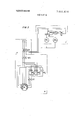
- FIG. 5 is a connection diagram of another automatic type of embodiment of this invention.
- FIG. 6 is a block diagram of the static voltage relay which is used in the embodiment shown in FIG. 5;
- FIGS. 7a and 7b are connection diagrams of windings in a dual-rated three-phase induction motor used in this invention, FIG. 7a being for use with a 400 v. class line voltage and FIG. 7b for use with a 200 v. class voltage;
- FIGS. 8a and 8b are connection diagrams of windings in a dual-rated single-phase induction motor used in this invention, FIG. 8a being for the use in a 400 v. system and FIG. 8b for the use in 200 v. system; and
- FIG. 9 is a connection diagram of an embodiment of this invention in which a transformer is used for adapting the loads to the line voltage of the different voltage classes.
- FIGS. 1, 2, 4 and 5 have been assumed to have the connections as shown in FIGS. 7a and 7b, and that singlephase motors and heaters are not shown in FIGS. 4 and 5 just for simplification of the explanation. Also, in FIG. 2, heaters are omitted for the same reason.
- connection diagram of the refrigerator unit is divided into three sections, that is, input section, load section and control section, respectively being indicated by characters A, B and C.
- characters R, S, T indicate power input terminals; particularly R,, S,, T, being such terminals which are to be connected with 200 v. class power lines, while R 8,, T are for 400 v. class power lines.
- Plugs P, and P indicate plugs connected with the input terminals R,, S,, T, and R 8,, T respectively through appropriate cables.
- Plugs P, and I have respectively different formations so as not to allow misconnection. That is to say, plug P, is adapted only to a 200 v. receptacle, while plug P only to a 400 v. receptacle.
- Reference character CB indicate a circuit breaker.
- the refrigerator includes a compressor, a condenser, an expansion valve and a cooler which constitute the known refrigerating cycle.
- the electric load includes a compressor motor M,, fan motors M and M for the condenser, and fan motors M and M for the cooler.
- the compressor motor M is a dual-voltage threephase induction motor and has delta-connected stator windings. Each branch of the delta consists of two windings which are to be connected in series for use in 400 v. lines as shown in FIG. 7a or connected in parallel for use in 200 v. lines as shown in FIG. 7b.
- the fan motors M M M, and M are single-phase induction motors. For 400 v. operation, windings of the single-phase motor may be connected as shown in FIG. 8a. That is, the main coil (u,v,) is connected in parallel with the series connection of the auxiliary coil (u, y) and a capacitor, and an additional coil (u -v is connected in series with the above parallel connection.
- connection should be as shown in FIG. 8b, the additional coil also being connected in parallel with the abovementioned parallel connection.
- Electromagnetic contactors MS controls the compressor motor M, and the condenser motors M and M while electromagnetic contactor MS controls the fan motors M and M, of the cooler.
- Reference character WS indicates a water switch.
- the refrigerator unit further includes a heater h, for defrosting the cooling coils and heating air, a second heater h for a drain pan and a third heater h, for a drain tube. These heaters h I1 h also are prepared for connection to either of 200 v. and 400 v. lines.
- An electromagnctic contactor MS controls the heater load.
- Reference character SS indicates a gang switch such as a multistage cam switch or a rotary switch, which is manually operated.
- the switch traversed by a dotand-dash line in the Figure are all included in this gang switch SS, of which switch contacts indicated with H are ones to be closed in the 400 v. operation, whereas those marked with L are closed in the 200 v. operation, interlock means being provided lest a H contact and a L contact should be closed at the same time.
- a transformer Tr is provided for supplying a control circuit with elec tric power.
- the secondary winding of the transformer Tr is provided with a midtap. In operation with a 200 v.
- the switch contact L is closed to connect one of the output terminals T and S of the transformer with one end of the secondary winding; while in the operation with a 400 v. source, the midtap is connected with said one of the output terminals through the switch contact H.
- the same voltage 24 v. appears across the output terminals T and S to which is connected the control circuit of the electromagnetic contactors.
- the input terminals R,, S,, T, or the input plug P is connected with the power line, after the gang switch SS is turned so as to close the L contacts. Then the circuit breaker CB and the electromagnetic contactors M8,, M5 M8 are closed in the same manner as in the previous case. Thus, the operation will start, 200 v. power being applied to the load adapted for the same voltage. If the gang switch SS is mistakenly operated to make the H contacts, no damage will occur as the power input is also cut off by the same gang switch SS.
- FIG. 2 The control system shown in FIG. 2 is substantially the same as that shown in FIG. I, except that some of the single-phase motors and the heaters are omitted in FIG. 2 in order to simplify the description of the operation of the gang switch in connection with FIG. 3.
- a transformer Tr for supplying electric power to the control circuits of the electromagnetic contactors MS,, MS, is provided with a midtap in the primary wind ing. In 400 v. operation, the power lines should be connected across both ends of the primary winding; while in 200 v. operation the power lines should be connected to the midtap and one end of the primary winding, so that a constant 24 v. secondary voltage is always maintained between the terminals R and S It will be understood that this dual voltage arrangement can be made in the secondary side of the transformer as in the first embodiment.
- the switch contacts L,-L and H,-H. are incorporated into a single cam switch.
- the arrangement of the contacts are shown in FIG. 3.
- L, and H indicate contacts for selecting the power input between a 200 v. line and a 400 v. line;
- L L and H contacts for changing connection of the windings of the compressor motor M,-, L,, L, and H, for changing connection of the windings of a single-phase motor M and L and H, for selecting the primary terminal of the transformer Tr,.
- the cam switch SS is turned to the position of notch No. I after the power plug P, is fitted to a mating power outlet.
- the contacts L,L are closed and H,-H., are opened, thereby supplying 200 v. power to the loads that are adapted for the same voltage.
- the cam switch SS is turned to notch No. 4 after the plug P is fitted to a 400 v. power outlet. This time the contacts H,--H are closed and L,L are opened, and the 400 v. power is supplied to the motors M,, M and the transformer Tr, which are all adapted to receive 400 v. power.
- the cam switch SS is provided with locking indents at the positions of notches No. I and No. 4, but such a locking means is not provided at the other positions, No. 2, No. 3 and the neutral point 0.
- the contacts of the switch SS are disposed in such a manner that in turning the switch SS by means of a lever from the notch No. 1 to notch No. 4 through notches No. 2, 0, No. 3, the contact L is opened immediately after the switch lever departs from the notch No. 1, while the other L contacts are opened only after the leer passes the notch No. 2. Further, the contacts H,I-I are closed at the position of the notch No. 3, but thecontact H, is closed only after the lever reaches the notch No. 4.
- the switch SS is constructed in a manner that the lever cannot be turned from the notch No. 1 directly to No. 4 not passing the notches No. 2, 0, No. 3, and vice ver- By the above'described structure of the cam switch SS is ensured safety in the operation relating to the selection of power voltage.
- the current interrupting capacity of the contacts in the cam switch can be greatly reduced, which results in such a switch of being constructed a much smaller size and having a longer life. That is, if the lever of the cam switch happens to be turned during operation of the refrigerator unit, the contact H (or L is opened prior to opening of the other contacts H,-H (or L,-L and therefore the electromagnetic contactors MS,, MS, which are designed to properly handle the respective load currents and which are energized from the transformer Tr, are opened prior to opening of the contacts H,-H (or L,-L Moreover, in starting the refrigerator unit, the contacts H,H (or L,L,-,) will always be closed prior to closing of the electromagnetic contactors.
- the contacts of the cam switch SS are assuredly exempted from dealing with heavy currents during the starting and the stopping periods of the operation. It should be noted, however, that it is usual practice in starting the refrigerator unit to energize the electromagnetic contactors MS,, MS manually by a pushbutton or automatically after the cam switch SS is set at the notch No. I or No. 4. Further, it should be understood that the cam switch SS may be remotely operated by means of a pilot motor incorporated therein. Other merits with this embodiment are the same as those described in connection with the previous embodiment.
- Still another embodiment of this invention will be described with reference to FIG. 4.
- the switching of the connections is achieved automatically using electromagnetic contactors which are mutually interlocked in the operation.
- a transformer Tr which supplies control power is provided a center tap 12 in the secondary winding.
- the transforming ratio of the transformer is such that if 400 v. is applied to the primary winding, 48 v. appears between both end b, and c of the secondary winding, while 24 v. appears between the end and the center terminal b
- a quick-acting auxiliary relay MR which is rated for 24 v.
- auxiliary relay MR of slow-acting type is connected between the terminals b, and c
- the latter relay MR also is rated for 24 v., but it can be operated at 48 v. for a short time.
- Switch contacts indicated by MS are make-contacts of an electromagnetic contactor whose coil is indicated by MC and switch contacts marked with M8, are actuated by coil MC
- contacts M8,, and MS are break-contacts, i.e., normally closed contacts respectively associated with coils MC and MC
- contacts mr, and mr are normally open contacts of the relays MR, and MR respectively, and contacts mr, and mr, are normally-closed contacts of the relays.
- a normally-closed contact mr, of the relay MR cut off the power to the relay MR before the latter can make any significant move.
- the coil MC of the electromagnetic contactor is energized through two normally-open contacts mr, and two normallyclosed contacts mr to close contacts MS and to open the contact M8,, connected in series with coil MC
- the inactivity of the electromagnetic contactor MC is ensured by two normally-closed contacts mr, of the relay MR, and a normally-closed contact MS,, of the contactor MC and therefore the contacts MS remain open.
- the compressor motor M is prepared for operation under 400 v., and upon closing electromagnetic contactor MS,, the motor M, will start safely.
- the line voltage is 200 v.
- that voltage is applied to the transformer Tr upon closing the circuit breaker CB.
- 24 v. and 12 v. will appear between terminals b, and c, and between terminals b and 0, respectively. Therefore, 12 v. is applied to the relay MR, and 24 v. to the relay MR
- the relay MR is designed to operate under 24 v. optimum voltage, it will not operated now with a voltage as low as l2 v.
- the relay MR is actuated, and the coil MC, of the contactor is energized to close the contacts MS while the coil MC is prevented from being energized, thereby to keep the contacts MS opened, in a similar manner as previously described. Therefore, the motor M, is adapted for 200 v. operation and will start safely upon closing the contactor M8,.
- FIG. 5 indicates a stepdown transformer, Ry a voltage relay of a static type and MR, an auxiliary relay with contacts Ta, Tb, Tc.
- the components of substantially the same functions as those shown in FIG. 4 are indicated by corresponding reference characters.
- the static relay Ry comprises, for example, a rectifying and filtering circuit, a voltage detecting circuit, a voltage regulating circuit and a driving circuit, as shown in FIG. 6. Es-
- sential components of the above circuits are semiconductor elements such as silicon rectifiers, transistors and SCR.
- Output of the transformer Tr is converted to a DC voltage through the rectifier and filter 61, and the DC-converted voltage is compared with a reference voltage form the voltage regulator 62, in the voltage detector 63.
- the resultant signal of the comparison indicating which voltage is higher, is applied to the power circuit 64, which in turn produces a constant output or no output depending on the level of the input voltage.
- the circuits of the relay are set so that said output is produced if the line voltage is in the 400 v. class but not ifit is in the 200 V. class.
- the output from the static relay Ry energizes the auxiliary relay MR to switch its movable contact T, from the normally-closed position (T to nonnally-opened position (T Accordingly, the coil MC is energized to close the contacts MS and the coil MC, remains inactive to keep the contacts MS, opened.
- the motor M is prepared for 400 v. operation, and if a pushbutton (not shown) is depressed to close the contactor MS,, it will start safely.
- overload detecting elements 0C are connected among windings of the compressor motor M, in a particular manner.
- the conventional arrangement of overload detecting elements for a motor that is adaptable to two classes of line voltages has been to connect two sets of such elements of different current ratings, each set for each line voltage, in series with a motor switch or breaker in two of the power lines or in all of three lines. With such an arrangement, however, the manufacturing cost involved in said elements as well as the space in the control box required for them are duplicated. Further, means for selecting either set of said two sets of elements according to the line voltage is required.-
- overload detecting elements per se are known art such as various types of combinations of heating elements and temperature-sensitive bimetallic element or electromagnetic coils with plungers; and it will be needless to explain that such a detecting element, if an overload occurs, triggers a nonnallyclosed contact in a control circuit of the electromagnetic contactor thereby to open the contactor and to stop the motor.
- reference characters R, S, T indicate power input terminals; U,, U,, V,, V W,, W X,, Y,, Z, terminals of the component windings of the motor M, shown in FIGS. 1, 2, 4 and 5; and d, e,f, d,, e,,f,, d e ,f conductors between windings.
- the overload detecting elements are connected in the portions d, e, f, or in either two of said three portions, in order to detect an overload current in the windings if it occurs.
- the same detecting elements with the same current rating are inserted in the portions d, (or d e, (or e ),f, (orf or either two of said three portions, to protect the motor from the overload.
- the line currents to the motor are of course different, the current in the 200 v. operation being approximately twice as large as for the 400 v. operation.
- the current flowing through each of the six component windings are the same in both cases, because in a 200 v. operation the phase current (i.e. the current between lines) which is two-fold that of the 400 v. operation is divided between two component windings as is obvious from FIGS.
- the control system shown in FIG. 9 includes a stepdown transformer Tr besides a small transformer Tr for control circuits.
- the loads and other components whose functions are substantially the same as those in the preceding embodiments are indicated by corresponding reference characters.
- the control section C of the system is shown to be the same as that in FIG. 5.
- the motors M,', M M M M and the heaters k h h are all rated for 200 v. and may not be provided with intermediate terminals, unlike in the preceding embodiments.
- the voltage relay Ry operates to actuate the auxiliary relay MR and accordingly to energize the coil MC of the electromagnetic contactor. Therefore, contacts MS is closed which contacts M8, is opened, and 400 v. power is applied to the 400 v./200 v. transformer Tr which supplies the loads with 200 v. power.
- the voltage relay Ry will not operate and the movable contact T of the auxiliary relay MR will remain at the normally-closed position, i.e., at the contact T Therefore, the contacts MS are closed while the contacts MS are kept pen.
- a refrigerated container can be used easily and safely at two places where available power is of difierent line voltages.
- the lower line voltage is 200 v. and the higher voltage is mostly 400 v. More generally, however, the lower voltage may be a voltage between 180 v. and 240 v., and any higher voltage ranging from 340 v. to 480 v. can be used for the refrigerator unit of this invention.
- a refrigerator unit for use in a freight container which may be commonly connected to available power lines of at least two classes of line voltage, said unit comprising:
- At least one duaLrated electric motor constructed so as to be adaptable to either of two classes of line voltages by simply changing electric connections of said motor
- said first means comprises two power input branches
- each branch including a power plug of a particular formation which does not fit a receptacle prepared for the other plug and a switch is interlocked with a switch of the other branch so as to operate contrari-wise, and
- said first means, second means and third means comprise a single gang switch.
- said gang switch includes an additional pair of component switch means connected in a control circuit of an electromagnetic contactor for selecting a terminal which insures that the rated voltage of said contactor matches with the line voltage,
- said second means comprises a group of electromagnetic contactors
- said first means comprises a voltage detecting means connected with the power lines of the unit, and
- said third means comprises an appropriate number of relays for controlling energization of exciting coils of said electromagnetic contactors according to the result of the de tection by said first means.
- a refrigerator unit as in claim 4, wherein said voltage detecting means comprises: t
- a transformer connected with the power lines of the unit for providing two classes of secondary voltages corresponding to said two classes of line voltages
- a quick-acting relay connected with lower voltage secondary terminals of said transformer for acting quickly when the refrigerator unit is connected with a power line of a higher voltage class but which will not act when the unit is connected with a power line of a lower voltage class
- a slow-acting relay connected with higher voltage secondary terminals of said transformer for acting slowly whenever the refrigerator unit is connected with either power line
- said quick-acting relay and said slow-acting relay being interlocked so as to prevent the opposite relay from operating when activated.
- said electric motor comprises a three-phase motor of which each of three delta-connected windings or star-connected windings comprises two substantially equal component windings and,
- said second means functions to change the connections of said component windings in each phase between series and parallel connections so that said refrigerator can be operated with either of two line voltages, one of which is substantially twice as high as the other voltage 8.
- a refrigerator unit as in claim 1, wherein:
- said electric motor comprises a three-phase, motor
- said second means functions to change the connections of phase windings of said motor between star connection and delta connection so that said refrigerator can be operated with either of two line voltages, one of which is substantially )1? times as high as the other voltage.
- a refrigerator unit as in claim 8 wherein an overload detecting element is connected in series with each of at leas two phase windings.
- a refrigerator unit used for a freight container comprising electric loads whose rated voltage is equal to one of two classes of line voltages with either of which said refrigerator unit is to be operated, a first means as to contributes to select one of said two classes of line voltages, a transformer to whose secondary terminals are connected said electric loads and which is constructed so that the secondary voltage thereof is equal to the rated voltage of said loads and accordingly to said one of two line voltages when a voltage equal to the other of said two line voltages is applied to the primary windings thereof, a second means for disconnecting said transformer from the power circuit and making a circuit bypassing said transformer, and a third means for interlocking said first means with said second means so as to match the rated voltage of said load with the voltage of the power line with which said refrigerator unit is connected.
- a refrigerator unit for use in a freight container which may be connected to either of different electrical supply lines providing at least two classes of line voltages without any danger of mismatching electrical loads with available line voltages, said unit comprising:
- At least one dual-rated electrical load which maybe operated at either of said two classes of line voltages by changing terminal connections thereto.
- interlock means for preventing the energization of said load unless said terminal connections are proper for matching the load to the available class of line voltage.
- said first means includes voltage detecting means for automatically determining the class of available line voltage connected thereto, and
- said second means and said interlock means comprise electrically controlled switch means connected to said first means and automatically controlled thereby.
Landscapes
- Engineering & Computer Science (AREA)
- Power Engineering (AREA)
- Physics & Mathematics (AREA)
- Mechanical Engineering (AREA)
- Thermal Sciences (AREA)
- General Engineering & Computer Science (AREA)
- Relay Circuits (AREA)
- Control Of Ac Motors In General (AREA)
Applications Claiming Priority (3)
| Application Number | Priority Date | Filing Date | Title |
|---|---|---|---|
| JP6223368U JPS5347639Y1 (enExample) | 1968-07-20 | 1968-07-20 | |
| JP413469U JPS5627489Y1 (enExample) | 1969-01-17 | 1969-01-17 | |
| JP803969U JPS5552778Y1 (enExample) | 1969-01-30 | 1969-01-30 |
Publications (1)
| Publication Number | Publication Date |
|---|---|
| US3601618A true US3601618A (en) | 1971-08-24 |
Family
ID=27276129
Family Applications (1)
| Application Number | Title | Priority Date | Filing Date |
|---|---|---|---|
| US841286A Expired - Lifetime US3601618A (en) | 1968-07-20 | 1969-07-14 | Refrigerator unit used for a freight container |
Country Status (3)
| Country | Link |
|---|---|
| US (1) | US3601618A (enExample) |
| FR (1) | FR2013418A1 (enExample) |
| GB (1) | GB1231720A (enExample) |
Cited By (9)
| Publication number | Priority date | Publication date | Assignee | Title |
|---|---|---|---|---|
| US3697771A (en) * | 1971-06-21 | 1972-10-10 | Carpetech Corp | Carpet cleaning apparatus with electrical power conditioning means |
| US4228388A (en) * | 1978-04-14 | 1980-10-14 | Overhead Conveyor Company | Control circuit responsive to utility voltage level |
| US20040164636A1 (en) * | 2003-02-20 | 2004-08-26 | Fanuc Ltd. | Electric motor |
| US20060139835A1 (en) * | 2002-12-10 | 2006-06-29 | Ryosaku Nakata | Device for protection from thunder |
| US20090108796A1 (en) * | 2006-05-22 | 2009-04-30 | Jae-Hak Choi | Starting Control Apparatus and Method for Motor |
| US20090316459A1 (en) * | 2008-06-19 | 2009-12-24 | Tork, Inc. | Electrical timer system that automatically operates over different supply voltages |
| US20110194224A1 (en) * | 2010-02-10 | 2011-08-11 | Hanchett Entry Systems, Inc. | Control Circuit for Electric Unlocking Devices Using Actuating Solenoids |
| US20140125269A1 (en) * | 2011-02-25 | 2014-05-08 | Whirlpool S.A. | Winding switching circuit and thermal protection for dual voltage hermetic induction motor of hermetic cooling compressor |
| US20190363534A1 (en) * | 2018-05-25 | 2019-11-28 | Gp Enterprises Co., Ltd. | Thermal protection device for single-phase dual-voltage motor |
Families Citing this family (2)
| Publication number | Priority date | Publication date | Assignee | Title |
|---|---|---|---|---|
| KR890003277B1 (ko) * | 1985-10-02 | 1989-09-06 | 산요덴끼 가부시기가이샤 | 전기가열기기 |
| FR3118110B1 (fr) | 2020-12-17 | 2025-09-05 | Psa Automobiles Sa | Dispositif de piège à vibrations distribué notamment pour un stator, ou carter, de machine électrique tournante |
Citations (1)
| Publication number | Priority date | Publication date | Assignee | Title |
|---|---|---|---|---|
| US2693539A (en) * | 1950-02-03 | 1954-11-02 | John J Madigan | Voltage modifier for circuits between disconnectible bodies |
-
1969
- 1969-07-14 US US841286A patent/US3601618A/en not_active Expired - Lifetime
- 1969-07-16 GB GB1231720D patent/GB1231720A/en not_active Expired
- 1969-07-18 FR FR6924679A patent/FR2013418A1/fr active Pending
Patent Citations (1)
| Publication number | Priority date | Publication date | Assignee | Title |
|---|---|---|---|---|
| US2693539A (en) * | 1950-02-03 | 1954-11-02 | John J Madigan | Voltage modifier for circuits between disconnectible bodies |
Cited By (13)
| Publication number | Priority date | Publication date | Assignee | Title |
|---|---|---|---|---|
| US3697771A (en) * | 1971-06-21 | 1972-10-10 | Carpetech Corp | Carpet cleaning apparatus with electrical power conditioning means |
| US4228388A (en) * | 1978-04-14 | 1980-10-14 | Overhead Conveyor Company | Control circuit responsive to utility voltage level |
| US20060139835A1 (en) * | 2002-12-10 | 2006-06-29 | Ryosaku Nakata | Device for protection from thunder |
| US7256977B2 (en) * | 2002-12-10 | 2007-08-14 | Nippon Kouatsu Electric Co., Ltd. | Device for protection from thunder |
| US20040164636A1 (en) * | 2003-02-20 | 2004-08-26 | Fanuc Ltd. | Electric motor |
| US8067920B2 (en) * | 2006-05-22 | 2011-11-29 | Lg Electronics Inc. | Starting control apparatus and method for motor |
| US20090108796A1 (en) * | 2006-05-22 | 2009-04-30 | Jae-Hak Choi | Starting Control Apparatus and Method for Motor |
| US20090316459A1 (en) * | 2008-06-19 | 2009-12-24 | Tork, Inc. | Electrical timer system that automatically operates over different supply voltages |
| US20110194224A1 (en) * | 2010-02-10 | 2011-08-11 | Hanchett Entry Systems, Inc. | Control Circuit for Electric Unlocking Devices Using Actuating Solenoids |
| US8687341B2 (en) * | 2010-02-10 | 2014-04-01 | Hanchett Entry Systems, Inc. | Control circuit for electric unlocking devices using actuating solenoids |
| USRE46546E1 (en) * | 2010-02-10 | 2017-09-12 | Hanchett Entry Systems, Inc. | Control circuit for electric unlocking devices using actuating solenoids |
| US20140125269A1 (en) * | 2011-02-25 | 2014-05-08 | Whirlpool S.A. | Winding switching circuit and thermal protection for dual voltage hermetic induction motor of hermetic cooling compressor |
| US20190363534A1 (en) * | 2018-05-25 | 2019-11-28 | Gp Enterprises Co., Ltd. | Thermal protection device for single-phase dual-voltage motor |
Also Published As
| Publication number | Publication date |
|---|---|
| FR2013418A1 (enExample) | 1970-04-03 |
| GB1231720A (enExample) | 1971-05-12 |
Similar Documents
| Publication | Publication Date | Title |
|---|---|---|
| US4068276A (en) | Protective system for electrical appliances | |
| US3601618A (en) | Refrigerator unit used for a freight container | |
| US3622867A (en) | Load tap changer system including protective apparatus for monitoring the operation thereof | |
| US4060841A (en) | Motor protector for three-phase motors | |
| US7081735B1 (en) | System and method for bypassing a motor drive | |
| CA1234905A (en) | 400 hz aircraft ground power supply | |
| US1007480A (en) | Alternating-electric-current-distribution system. | |
| RU2006135C1 (ru) | Устройство для симметрирования неполнофазных режимов | |
| US2240207A (en) | Protective system | |
| US2486004A (en) | Phase reversal protector | |
| GB2043971A (en) | Voltage regulators | |
| US2275881A (en) | Fault protective system | |
| US1526027A (en) | Phase-selecting relay | |
| US5500582A (en) | Multiphase load control system with switch connected split sources of phase voltage | |
| US714181A (en) | Tripping electric switches or circuit-breakers. | |
| US2300857A (en) | Overload protection for multispeed motors | |
| US926243A (en) | System of electric-circuit control. | |
| US2006997A (en) | Circuit breaker control system | |
| US2188804A (en) | Control system | |
| SU1133154A1 (ru) | Устройство дл управлени стрелочным электроприводом | |
| GB2088658A (en) | A starting circuit for a single-phase induction motor | |
| SU1359844A1 (ru) | Устройство дл защиты от неполнофазных режимов работы трехфазной электрической сети | |
| US2393949A (en) | Control system | |
| SU1259386A1 (ru) | Устройство дл защиты трехфазной нагрузки от обрыва фазных цепей и пробо изол ции на корпус | |
| US1785722A (en) | Control system |