US3599385A - Wood floor finishing construction - Google Patents
Wood floor finishing construction Download PDFInfo
- Publication number
- US3599385A US3599385A US861043A US3599385DA US3599385A US 3599385 A US3599385 A US 3599385A US 861043 A US861043 A US 861043A US 3599385D A US3599385D A US 3599385DA US 3599385 A US3599385 A US 3599385A
- Authority
- US
- United States
- Prior art keywords
- prongs
- panels
- abutting
- clip
- subfloor
- Prior art date
- Legal status (The legal status is an assumption and is not a legal conclusion. Google has not performed a legal analysis and makes no representation as to the accuracy of the status listed.)
- Expired - Lifetime
Links
Images

Classifications
-
- E—FIXED CONSTRUCTIONS
- E04—BUILDING
- E04F—FINISHING WORK ON BUILDINGS, e.g. STAIRS, FLOORS
- E04F15/00—Flooring
- E04F15/02—Flooring or floor layers composed of a number of similar elements
- E04F15/04—Flooring or floor layers composed of a number of similar elements only of wood or with a top layer of wood, e.g. with wooden or metal connecting members
-
- E—FIXED CONSTRUCTIONS
- E04—BUILDING
- E04F—FINISHING WORK ON BUILDINGS, e.g. STAIRS, FLOORS
- E04F2201/00—Joining sheets or plates or panels
- E04F2201/01—Joining sheets, plates or panels with edges in abutting relationship
-
- E—FIXED CONSTRUCTIONS
- E04—BUILDING
- E04F—FINISHING WORK ON BUILDINGS, e.g. STAIRS, FLOORS
- E04F2201/00—Joining sheets or plates or panels
- E04F2201/02—Non-undercut connections, e.g. tongue and groove connections
- E04F2201/023—Non-undercut connections, e.g. tongue and groove connections with a continuous tongue or groove
-
- E—FIXED CONSTRUCTIONS
- E04—BUILDING
- E04F—FINISHING WORK ON BUILDINGS, e.g. STAIRS, FLOORS
- E04F2201/00—Joining sheets or plates or panels
- E04F2201/05—Separate connectors or inserts, e.g. pegs, pins, keys or strips
- E04F2201/0511—Strips or bars, e.g. nailing strips
-
- E—FIXED CONSTRUCTIONS
- E04—BUILDING
- E04F—FINISHING WORK ON BUILDINGS, e.g. STAIRS, FLOORS
- E04F2201/00—Joining sheets or plates or panels
- E04F2201/05—Separate connectors or inserts, e.g. pegs, pins, keys or strips
- E04F2201/0517—U- or C-shaped brackets and clamps
Definitions
- Robic ABSTRACT A finishing wood covering laid over a subfloor and comprising a plurality of finishing wood panels secured over the subfloor in edge abutting relationship with each other, each panel being cut out along the abutting edges to define a recess, at the top, having a horizontal ledge and an inclined inner lateral wall, and being further cut out at the bottom along the abutting edges to form a horizontal groove.
- the recess and the groove of a panel define therebetween an overhanging tongue that extends fully around the panel, the top recesses of abutting panels thus having a dovetail configuration.
- a plurality of fastening clips are mounted on the tongues of abutting panels to hold them together and fasten them to the floor.
- Each clip is formed of an upstanding web disposed between the facing ends of the tongues of the corresponding abutting panels and lateral prongs projecting from the top and bottom of the upstanding web to overlie the horizontal ledges of the tongues and to be received in the bottom grooves of the corresponding abutting panels, respectively.
- two spaced bottom prongs that extend in the said opposite direction while a further bottom prong extends in the one direction aforesaid between the first bottom prongs.
- the panels are secured to the subframe by means of a nail, for each clip, driven in the space between the first two top prongs, driven through the tongue, through the further bottom prong and into the subfloor Finally, filler wood strips of dovetail cross section are set in the said recesses defined between the abutting panels.
- the present invention relates to the construction of wooden floor surfaces and particularly to a finishing layer of wood on a prepared unfinished subfloor surface.
- the present invention proposes a new form of sheetlike boards or panels along with fastening edge clips and which are intended for use in constructing finished wood floors and do not present any of the aforementioned disadvantages and furthermore present advantages of its own; one of these advantages having to do with the relatively great rapidity with which the finishing of floors in accordance with the present invention can be achieved.
- the invention proposes a finishing wood covering laid over a subfloor, said covering comprising: a plurality of finishing wood panels secured over said subfloor in edge abutting relationship with one another; each of said panels being cut out along the abutting edges thereof to define a continuous recess at the top, having a horizontal ledge and an inclined inner lateral wall, each panel being further cut out at the bottom along said edges to form a continuous horizontal groove; the recess and the groove of a panel defining therebetween a continuous overhanging tongue extending fully around said panel, the top recesses of abutting panels thus having a dovetail configuration; a plurality of fastening clips mounted on tongues of abutting panels; each of said clips being formed of an upstanding web disposed between the facing ends of the tongues of corresponding abutting panels, and lateral prongs projecting from the top and bottom of said upstanding webs to overlie the horizontal ledges of said tongues and to be received in said bottom grooves of the corresponding abut
- FIG. I is a perspective view of a floor corner in accordance with the present invention and showing a partially installed sheet board
- FIG. 2 is an exploded fractional perspective view showing how an assembly of adjacent and consecutive boards is realized in accordance with the invention
- FIG. 3 is a sectional view taken on line 3-3 of FIG. 1;
- FIG. 4 is a sectional view taken on line 4-4 of FIG. 2.
- sheets or panels 1 of laminated wood or of particle board are used; each sheet I presenting a number of square or rectangular surfaces 2 which are defined by a series of grooves 3 and 4 of rectangular cross section which have depth which slightly exceeds the thickness of a filler strip 5 to be received therein.
- each strip 5 is thereafter inserted in grooves 3 and 4 and securely fastened therein by means of an appropriate glue, cement or bedding compound.
- the thickness of each strip 5 is such that, as it rests over the heads of the nails 6, the top surface thereof lies in the plane of the surface of the sheet 1.
- each sheet 1 there is a groove 10 the width of which, measured in the plane of the top surface of the sheet, is less than half the width of any groove 3 or 4.
- the upright wall 11 of groove 10 is sloped inwardly so that when adjacent sheets 1 are brought together the respective grooves 10 combine to form a track of dovetail cross section.
- edging clips 13 are used for interconnecting the abutting edges of adjacent sheets 1 and as a means for preventing any up or down displacement of the edge of one sheet relative to the edge of the other and vice versa.
- the clip 13 is preferably made of sheet metal such as galvanized steel and consists of a double-ended three-pronged fork in which there is a transverse alternation of prongs l5 and 16 which are disposed according to two spaced apart horizontal planes corresponding to the bottom surfaces 17 and 18 respectively of the peripheral grooves 10 and 12.
- each sheet is completely nailed down such as by means of nails 6 and 6 before any other sheet is brought to adjoin.
- the nails 6 are used to fasten down the marginal portion of the sheet 1 and are preferably driven at positions along the bottom of the groove 10 where they will be adjacent to one of the prongs I5 and overlie and puncture through one of the underlying prongs 16.
- any sheet 1 has been completely fastened down by means of nails 6 and 6 and clips 13 have been positioned and simultaneously secured by nails 6' at spacedintervals along the free edges thereof, some strips 20 are positioned into the groove 10, (i.e. resting over the heads of nails 6' and the prongs 15) prior to bringing any adjacent sheet 1 into position with the edge thereof within the grip of the prongs l5 and 16 of the free ends of the clips 13. It is seen therefore that of the abutting edges of any two adjacent sheets 1 only one is fastened down by means of nails 6', the other being secured or held down by means of clip 13 only.
- the filler strip 20 has a dovetail profile whereby it becomes locked in position when adjacent sheets 1 are brought together; the width of the strip 20 at the top would normally be equal to the width of any filler strip 5. Additionally, it is recommended that in order to be more securely fastened the strip 20 should be properly bedded by means ofglue, cement or other suitable bedding compound.
- a finishing wood covering laid over a subfloor, said received in said bottom grooves of the corresponding covering comprising:
- each clip two spaced top prongs extending each of Said Panels being all out along the abutting edges 5 in one direction from said web and a further top prong exthereof to define a continuous recess at the top having a horizontal ledge and an inclined inner lateral wall, each panel being further out out at the bottom along said edges to form a continuous horizontal groove; the recess and there also being for each clip two spaced bottom prongs extending in said opposite direction and a further bottom 5522:: :2 2 52 5235222 5 2;322:533; g j g nen extending in said one direction between said first ottom prongs; 2 :3 fggiigf ti gfzfgzzigggif of abumng panels thus g.
- each clip mounted on tongues of prongs Sa.
Abstract
A finishing wood covering laid over a subfloor and comprising a plurality of finishing wood panels secured over the subfloor in edge abutting relationship with each other, each panel being cut out along the abutting edges to define a recess, at the top, having a horizontal ledge and an inclined inner lateral wall, and being further cut out at the bottom along the abutting edges to form a horizontal groove. The recess and the groove of a panel define therebetween an overhanging tongue that extends fully around the panel, the top recesses of abutting panels thus having a dovetail configuration. A plurality of fastening clips are mounted on the tongues of abutting panels to hold them together and fasten them to the floor. Each clip is formed of an upstanding web disposed between the facing ends of the tongues of the corresponding abutting panels and lateral prongs projecting from the top and bottom of the upstanding web to overlie the horizontal ledges of the tongues and to be received in the bottom grooves of the corresponding abutting panels, respectively. There is for each clip, two spaced top prongs extending in one direction from the web and a further top prong extending in opposite direction between the first two prongs. There is also provided, for each clip, two spaced bottom prongs that extend in the said opposite direction while a further bottom prong extends in the one direction aforesaid between the first bottom prongs. The panels are secured to the subframe by means of a nail, for each clip, driven in the space between the first two top prongs, driven through the tongue, through the further bottom prong and into the subfloor. Finally, filler wood strips of dovetail cross section are set in the said recesses defined between the abutting panels.
Description
United States Patentv 172) Inventor Leonard LaRue S69 Belec St., St. Dorothy, Laval, Quebec, Canada [21] AppLNo. 861,043 [22] Filed Sept. 25,1969 [45] Patented Aug. 17,1971 [32] Priority Oct. I, I968 [33] Canada [31] 031403 [54] WOOD FLOOR FINISHING CONSTRUCTION 1 Claim, 4Drawing Figs.
[52] 0.8.01. 52/460, 52/471, 52/582 [51] Int.Cl.........,......' E04! 15/14 [50] FieldofSearch 52/459, 460,463,471,479,39l,582,586,314
[ 56] References Cited UNITED STATES PATENTS 662,376 ll/l900 Go'ehstm .7 52/586 1,533,074 4/1925 Denning. 52/586 2,200,649 5/1940 Wardle .r 52/582 2,253,667 8/1941 Warner r. 52/459X 2,337,156 12/1943 Elmendorf 52/582 2,849,759 9/1958 Burdette v 52/586X 2,851,740 911958 Baker 52/479 3,085,301 4/1963 Nuorivaara 52/471X Primary Examiner-Price C. Faw, Jr. Attorney Raymond A. Robic ABSTRACT: A finishing wood covering laid over a subfloor and comprising a plurality of finishing wood panels secured over the subfloor in edge abutting relationship with each other, each panel being cut out along the abutting edges to define a recess, at the top, having a horizontal ledge and an inclined inner lateral wall, and being further cut out at the bottom along the abutting edges to form a horizontal groove. The recess and the groove of a panel define therebetween an overhanging tongue that extends fully around the panel, the top recesses of abutting panels thus having a dovetail configuration. A plurality of fastening clips are mounted on the tongues of abutting panels to hold them together and fasten them to the floor. Each clip is formed of an upstanding web disposed between the facing ends of the tongues of the corresponding abutting panels and lateral prongs projecting from the top and bottom of the upstanding web to overlie the horizontal ledges of the tongues and to be received in the bottom grooves of the corresponding abutting panels, respectively. There is for each clip, two spaced top prongs extending in one direction from the web and a further top prong extending in opposite direction between the first two prongs. There is also provided, for each clip, two spaced bottom prongs that extend in the said opposite direction while a further bottom prong extends in the one direction aforesaid between the first bottom prongs. The panels are secured to the subframe by means of a nail, for each clip, driven in the space between the first two top prongs, driven through the tongue, through the further bottom prong and into the subfloor Finally, filler wood strips of dovetail cross section are set in the said recesses defined between the abutting panels.
PATENTED AUG] 7:971
SHEET 1 BF 2 INVENTOR Leonard LA RUE ATTORNEY PATENTEU AUG 17 Ian sum 2 0F 2 INVENTOR Leonard LA RUE A TTORNE Y WOOD FLOOR FINISHING CONSTRUCTION The present invention relates to the construction of wooden floor surfaces and particularly to a finishing layer of wood on a prepared unfinished subfloor surface.
It is commonly known to finish wooden floors by the addition over the unfinished subfloor surface of a layer of hardwood in the form of narrow planks. It is also generally accepted that composite sheetlike boards of wood are not a suitable material for the finishing of floors. This hitherto nonexistent utility for sheetlike wood boardsor panels such as plywood and various forms of so-called particle boards, stems mostly from the fact that regardless of the skill that goes into producing the joints between consecutive sheets, such joints always remain apparent and unsightly unless extreme precautions are observed to ensure a perfect match or continuity of the wood grain between consecutive sheets.
The relatively large dimensions of plywood or particle boards or panels are such that they necessitate being nailed down or otherwise secured at positions intermediate between the edges thereof and the nails or other fastening means used for this purpose cannot easily be rendered non apparent.
The present invention proposes a new form of sheetlike boards or panels along with fastening edge clips and which are intended for use in constructing finished wood floors and do not present any of the aforementioned disadvantages and furthermore present advantages of its own; one of these advantages having to do with the relatively great rapidity with which the finishing of floors in accordance with the present invention can be achieved.
More specifically, the invention proposes a finishing wood covering laid over a subfloor, said covering comprising: a plurality of finishing wood panels secured over said subfloor in edge abutting relationship with one another; each of said panels being cut out along the abutting edges thereof to define a continuous recess at the top, having a horizontal ledge and an inclined inner lateral wall, each panel being further cut out at the bottom along said edges to form a continuous horizontal groove; the recess and the groove of a panel defining therebetween a continuous overhanging tongue extending fully around said panel, the top recesses of abutting panels thus having a dovetail configuration; a plurality of fastening clips mounted on tongues of abutting panels; each of said clips being formed of an upstanding web disposed between the facing ends of the tongues of corresponding abutting panels, and lateral prongs projecting from the top and bottom of said upstanding webs to overlie the horizontal ledges of said tongues and to be received in said bottom grooves of the corresponding abutting panels, respectively; there being for each clip two spaced top prongs extending in one direction from said web and a further top prong extending in opposite direction between the first two prongs; there also being for each clip two spaced bottom prongs extending in said opposite direction and a further bottom prong extending in said one direction between said first bottom prongs; a nail in said space, of each clip, between the two first top prongs, said nail being driven through said tongue, through said further bottom prong and into said subfloor, and filler wooden strips of dovetail cross section in said recesses defined between abutting panels.
In the accompanying drawing:
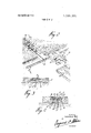
FIG. I is a perspective view of a floor corner in accordance with the present invention and showing a partially installed sheet board;
FIG. 2 is an exploded fractional perspective view showing how an assembly of adjacent and consecutive boards is realized in accordance with the invention;
FIG. 3 is a sectional view taken on line 3-3 of FIG. 1; and
FIG. 4 is a sectional view taken on line 4-4 of FIG. 2.
It is observed that in constructing floors in accordance with the invention sheets or panels 1 of laminated wood or of particle board are used; each sheet I presenting a number of square or rectangular surfaces 2 which are defined by a series of grooves 3 and 4 of rectangular cross section which have depth which slightly exceeds the thickness of a filler strip 5 to be received therein. Once it has been properly positioned any board 1 is secured into place by means of nails 6 or similar fasteners which are driven therethrough and into the underlyingsubfloor structure; nails 6 are driven through the sheets 1 only at spaced apart positions along the bottom surfaces of the grooves 3 and 4, the head of each nail projecting over the surface of the bottom of the groove in each case.
The filler strips 5 are thereafter inserted in grooves 3 and 4 and securely fastened therein by means of an appropriate glue, cement or bedding compound. The thickness of each strip 5 is such that, as it rests over the heads of the nails 6, the top surface thereof lies in the plane of the surface of the sheet 1.
Peripherally of each sheet 1, there is a groove 10 the width of which, measured in the plane of the top surface of the sheet, is less than half the width of any groove 3 or 4. The upright wall 11 of groove 10 is sloped inwardly so that when adjacent sheets 1 are brought together the respective grooves 10 combine to form a track of dovetail cross section. Also peripherally of each sheet 1 but at the underside thereof there is also a shallow groove 12 the depth of which is equal to the thickness of the metal used for a sheet metal edging clip 13.
With particular reference to FIG. 4, edging clips 13 are used for interconnecting the abutting edges of adjacent sheets 1 and as a means for preventing any up or down displacement of the edge of one sheet relative to the edge of the other and vice versa.
The clip 13 is preferably made of sheet metal such as galvanized steel and consists of a double-ended three-pronged fork in which there is a transverse alternation of prongs l5 and 16 which are disposed according to two spaced apart horizontal planes corresponding to the bottom surfaces 17 and 18 respectively of the peripheral grooves 10 and 12.
In the process oflaying out a finished floor according to the invention, each sheet is completely nailed down such as by means of nails 6 and 6 before any other sheet is brought to adjoin. The nails 6 are used to fasten down the marginal portion of the sheet 1 and are preferably driven at positions along the bottom of the groove 10 where they will be adjacent to one of the prongs I5 and overlie and puncture through one of the underlying prongs 16.
Once any sheet 1 has been completely fastened down by means of nails 6 and 6 and clips 13 have been positioned and simultaneously secured by nails 6' at spacedintervals along the free edges thereof, some strips 20 are positioned into the groove 10, (i.e. resting over the heads of nails 6' and the prongs 15) prior to bringing any adjacent sheet 1 into position with the edge thereof within the grip of the prongs l5 and 16 of the free ends of the clips 13. It is seen therefore that of the abutting edges of any two adjacent sheets 1 only one is fastened down by means of nails 6', the other being secured or held down by means of clip 13 only.
It must be understood that the filler strip 20 has a dovetail profile whereby it becomes locked in position when adjacent sheets 1 are brought together; the width of the strip 20 at the top would normally be equal to the width of any filler strip 5. Additionally, it is recommended that in order to be more securely fastened the strip 20 should be properly bedded by means ofglue, cement or other suitable bedding compound.
The embodiment of the invention herei-nbefore described may be observed to produce a checkered floor surface but it should he understood that, without departing from the invention, it would be possible to produce floor surfaces of various other designs, depending on the actual size and proportions of the basic sheetlike board unit. A preferred other design would result, for instance, from the use of sheetlike basic units of elongated rectangular configuration, having the same widths but unequal lengths; the resulting design would resemble that of a planked floor in which there is a narrow strip of wood separating every pair of longitudinally or transversely adjacent planks.
Iclaim:
overlie the horizontal ledge of said tongues and to be 1. A finishing wood covering laid over a subfloor, said received in said bottom grooves of the corresponding covering comprising:
a. a plurality of finishing wood panels secured over said subpanels respectively;
floor in g abutting relationship with one another; e. there being for each clip two spaced top prongs extending each of Said Panels being all out along the abutting edges 5 in one direction from said web and a further top prong exthereof to define a continuous recess at the top having a horizontal ledge and an inclined inner lateral wall, each panel being further out out at the bottom along said edges to form a continuous horizontal groove; the recess and there also being for each clip two spaced bottom prongs extending in said opposite direction and a further bottom 5522:: :2 2 52 5235222 5 2;322:533; g j g nen extending in said one direction between said first ottom prongs; 2 :3 fggiigf ti gfzfgzzigggif of abumng panels thus g. a nail in said space of each clip between the two first top a plurality of fastening clips mounted on tongues of prongs Sa.|d being dnven thrmfgh Sa.ld tongue: abutting panels; 15 through said further bottom prong and into said subfloor, each of said clips being formed of an upstanding web and disposed between the facing ends of tongues of the cop h. filler wooden strips of dove tail cross section in said responding abutting panels, and lateral prongs projecting recesses defined between abumng panels from the top and the bottom of said upstanding web to
Claims (1)
1. A finishing wood covering laid over a subfloor, said covering comprising: a. a plurality of finishing wood panels secured over said subfloor in edge abutting relationship with one another; b. each of said panels being cut out along the abutting edges thereof to define a continuous recess at the top having a horizontal ledge and an inclined inner lateral wall, each panel being further cut out at the bottom along said edges to form a continuous horizontal groove; the recess and groove of a panel defining therebetween an overhanging tongue having a facing end and extending fully around said panel, the recesses at the top of abutting panels thus having a dovetail cross section; c. a plurality of fastening clips mounted on tongues of abutting panels; d. each of said clips being formed of an upstanding web disposed between the facing ends of tongues of the corresponding abutting panels, and lateral prongs projecting from the top and the bottom of said upstanding web to overlie the horizontal ledge of said tongues and to be received in said bottom grooves of the corresponding panels respectively; e. there being for each clip two spaced toP prongs extending in one direction from said web and a further top prong extending in opposite direction between the first two top prongs; f. there also being for each clip two spaced bottom prongs extending in said opposite direction and a further bottom prong extending in said one direction between said first bottom prongs; g. a nail in said space of each clip between the two first top prongs, said nail being driven through said tongue, through said further bottom prong and into said subfloor; and h. filler wooden strips of dovetail cross section in said recesses defined between abutting panels.
Applications Claiming Priority (1)
| Application Number | Priority Date | Filing Date | Title |
|---|---|---|---|
| CA31403 | 1968-10-01 |
Publications (1)
| Publication Number | Publication Date |
|---|---|
| US3599385A true US3599385A (en) | 1971-08-17 |
Family
ID=4084537
Family Applications (1)
| Application Number | Title | Priority Date | Filing Date |
|---|---|---|---|
| US861043A Expired - Lifetime US3599385A (en) | 1968-10-01 | 1969-09-25 | Wood floor finishing construction |
Country Status (2)
| Country | Link |
|---|---|
| US (1) | US3599385A (en) |
| CA (1) | CA849766A (en) |
Cited By (14)
| Publication number | Priority date | Publication date | Assignee | Title |
|---|---|---|---|---|
| US3802142A (en) * | 1972-10-13 | 1974-04-09 | C Fehr | Ceiling panels |
| US4443988A (en) * | 1981-10-02 | 1984-04-24 | Atlas Insulation Company, Inc. | Insulated building panel |
| US4988131A (en) * | 1988-07-08 | 1991-01-29 | Sico Incorporated | Interlocking sections for portable floors and the like |
| US5022200A (en) * | 1988-07-08 | 1991-06-11 | Sico Incorporated | Interlocking sections for portable floors and the like |
| US6128881A (en) * | 1998-10-22 | 2000-10-10 | Sico Incorporated | Portable floor |
| US6189283B1 (en) | 1995-12-05 | 2001-02-20 | Sico Incorporated | Portable floor |
| WO2005089371A2 (en) * | 2004-03-16 | 2005-09-29 | Crowson Enterprises Llc | Synthetic ice surface systems and methods thereof |
| US20060024465A1 (en) * | 2004-07-30 | 2006-02-02 | Jean Briere | Laminate flooring members |
| US20080302052A1 (en) * | 2007-06-08 | 2008-12-11 | Kelly Gibson | Panelling system formed from panels defined by tongue and groove strips |
| US20090183458A1 (en) * | 2008-01-18 | 2009-07-23 | Kelly Gibson | Panelling system |
| US20140290164A1 (en) * | 2013-04-01 | 2014-10-02 | E I Du Pont De Nemours And Company | Insulated framing member |
| US20190383029A1 (en) * | 2018-06-14 | 2019-12-19 | Société en Commandite Prolam | Slip-resistant floor for a cargo-carrying apparatus |
| US20200340189A1 (en) * | 2019-04-29 | 2020-10-29 | Anthony DiNorcia | Paver tile attachment system |
| US20220049492A1 (en) * | 2020-08-12 | 2022-02-17 | Randy Gordon | Construction attachment member |
Families Citing this family (2)
| Publication number | Priority date | Publication date | Assignee | Title |
|---|---|---|---|---|
| WO2008148198A1 (en) * | 2007-06-08 | 2008-12-11 | Q4 Technologies Ltd. | Panelling system |
| CA2616254A1 (en) * | 2008-01-18 | 2008-04-08 | Kelly Gibson | Panelling system |
Citations (8)
| Publication number | Priority date | Publication date | Assignee | Title |
|---|---|---|---|---|
| US662376A (en) * | 1899-12-12 | 1900-11-20 | Edward Goehst | Floor. |
| US1533074A (en) * | 1920-10-04 | 1925-04-07 | Endicott Johnson Corp | Floor and process of laying floor |
| US2200649A (en) * | 1939-04-07 | 1940-05-14 | James B Wardle | Anchoring clip for artificial brick siding and the like |
| US2253667A (en) * | 1937-09-20 | 1941-08-26 | Warren A Warner | Plywood wallboard |
| US2337156A (en) * | 1941-04-03 | 1943-12-21 | Elmendorf Armin | Wood tile flooring |
| US2849759A (en) * | 1956-07-13 | 1958-09-02 | Burdette Harold William | Brick-simulating wood panel |
| US2851740A (en) * | 1953-04-15 | 1958-09-16 | United States Gypsum Co | Wall construction |
| US3085301A (en) * | 1959-03-19 | 1963-04-16 | Nuorivaara Enzio | Assembly of boards |
-
1968
- 1968-10-01 CA CA849766A patent/CA849766A/en not_active Expired
-
1969
- 1969-09-25 US US861043A patent/US3599385A/en not_active Expired - Lifetime
Patent Citations (8)
| Publication number | Priority date | Publication date | Assignee | Title |
|---|---|---|---|---|
| US662376A (en) * | 1899-12-12 | 1900-11-20 | Edward Goehst | Floor. |
| US1533074A (en) * | 1920-10-04 | 1925-04-07 | Endicott Johnson Corp | Floor and process of laying floor |
| US2253667A (en) * | 1937-09-20 | 1941-08-26 | Warren A Warner | Plywood wallboard |
| US2200649A (en) * | 1939-04-07 | 1940-05-14 | James B Wardle | Anchoring clip for artificial brick siding and the like |
| US2337156A (en) * | 1941-04-03 | 1943-12-21 | Elmendorf Armin | Wood tile flooring |
| US2851740A (en) * | 1953-04-15 | 1958-09-16 | United States Gypsum Co | Wall construction |
| US2849759A (en) * | 1956-07-13 | 1958-09-02 | Burdette Harold William | Brick-simulating wood panel |
| US3085301A (en) * | 1959-03-19 | 1963-04-16 | Nuorivaara Enzio | Assembly of boards |
Cited By (18)
| Publication number | Priority date | Publication date | Assignee | Title |
|---|---|---|---|---|
| US3802142A (en) * | 1972-10-13 | 1974-04-09 | C Fehr | Ceiling panels |
| US4443988A (en) * | 1981-10-02 | 1984-04-24 | Atlas Insulation Company, Inc. | Insulated building panel |
| US4988131A (en) * | 1988-07-08 | 1991-01-29 | Sico Incorporated | Interlocking sections for portable floors and the like |
| US5022200A (en) * | 1988-07-08 | 1991-06-11 | Sico Incorporated | Interlocking sections for portable floors and the like |
| US6189283B1 (en) | 1995-12-05 | 2001-02-20 | Sico Incorporated | Portable floor |
| US6128881A (en) * | 1998-10-22 | 2000-10-10 | Sico Incorporated | Portable floor |
| US7347788B2 (en) * | 2004-03-16 | 2008-03-25 | Crowson Enterprises Llc | Synthetic ice surface systems and methods thereof |
| WO2005089371A2 (en) * | 2004-03-16 | 2005-09-29 | Crowson Enterprises Llc | Synthetic ice surface systems and methods thereof |
| US20050245332A1 (en) * | 2004-03-16 | 2005-11-03 | Smith George T Ii | Synthetic ice surface systems and methods thereof |
| WO2005089371A3 (en) * | 2004-03-16 | 2007-02-01 | Crowson Entpr Llc | Synthetic ice surface systems and methods thereof |
| US20060024465A1 (en) * | 2004-07-30 | 2006-02-02 | Jean Briere | Laminate flooring members |
| US20080302052A1 (en) * | 2007-06-08 | 2008-12-11 | Kelly Gibson | Panelling system formed from panels defined by tongue and groove strips |
| US20090183458A1 (en) * | 2008-01-18 | 2009-07-23 | Kelly Gibson | Panelling system |
| US20140290164A1 (en) * | 2013-04-01 | 2014-10-02 | E I Du Pont De Nemours And Company | Insulated framing member |
| US20190383029A1 (en) * | 2018-06-14 | 2019-12-19 | Société en Commandite Prolam | Slip-resistant floor for a cargo-carrying apparatus |
| US20200340189A1 (en) * | 2019-04-29 | 2020-10-29 | Anthony DiNorcia | Paver tile attachment system |
| US20220049492A1 (en) * | 2020-08-12 | 2022-02-17 | Randy Gordon | Construction attachment member |
| US11788276B2 (en) * | 2020-08-12 | 2023-10-17 | Randy Gordon | Construction attachment member |
Also Published As
| Publication number | Publication date |
|---|---|
| CA849766A (en) | 1970-08-25 |
Similar Documents
| Publication | Publication Date | Title |
|---|---|---|
| US3599385A (en) | Wood floor finishing construction | |
| US1660480A (en) | Parquet-floor panels | |
| US1575821A (en) | Parquet-floor composite sections | |
| US2276071A (en) | Panel construction | |
| US2872712A (en) | Wall board construction | |
| CA1107476A (en) | Wall constructed from wallboard held together with concealed fasteners | |
| US3267630A (en) | Flooring systems | |
| US4471012A (en) | Square-edged laminated wood strip or plank materials | |
| US1988201A (en) | Reenforced flooring and method | |
| US4117644A (en) | Wallboard fastener | |
| US2337156A (en) | Wood tile flooring | |
| US3987599A (en) | Wood paneling | |
| US2269926A (en) | Composite board flooring | |
| US1946646A (en) | Floor | |
| US3875719A (en) | Metal support for wood structural elements | |
| US3640044A (en) | Prefabricated panel of shingles | |
| US2706838A (en) | Surfacing for walls of buildings | |
| US5165212A (en) | Hollow panel wall assembly | |
| RU2007120756A (en) | FLOOR COVERING SYSTEM HAVING MANY PLACES OF COMBINATION | |
| US3992829A (en) | Building structure | |
| US2766488A (en) | Inter-locking wall construction | |
| US3439464A (en) | Floor and wall system | |
| US2222137A (en) | Wood block flooring | |
| US4731970A (en) | Shingled building panel | |
| US2283582A (en) | Wall panel |