US3598103A - Underwater heating system - Google Patents
Underwater heating system Download PDFInfo
- Publication number
- US3598103A US3598103A US825814A US3598103DA US3598103A US 3598103 A US3598103 A US 3598103A US 825814 A US825814 A US 825814A US 3598103D A US3598103D A US 3598103DA US 3598103 A US3598103 A US 3598103A
- Authority
- US
- United States
- Prior art keywords
- chemical
- water
- heating tube
- heat exchanger
- reservoir
- Prior art date
- Legal status (The legal status is an assumption and is not a legal conclusion. Google has not performed a legal analysis and makes no representation as to the accuracy of the status listed.)
- Expired - Lifetime
Links
- 238000010438 heat treatment Methods 0.000 title claims abstract description 76
- XLYOFNOQVPJJNP-UHFFFAOYSA-N water Substances O XLYOFNOQVPJJNP-UHFFFAOYSA-N 0.000 claims abstract description 58
- QGZKDVFQNNGYKY-UHFFFAOYSA-N Ammonia Chemical compound N QGZKDVFQNNGYKY-UHFFFAOYSA-N 0.000 claims abstract description 55
- 239000000126 substance Substances 0.000 claims abstract description 51
- 229910021529 ammonia Inorganic materials 0.000 claims abstract description 25
- 238000006243 chemical reaction Methods 0.000 claims abstract description 10
- 239000007788 liquid Substances 0.000 claims description 17
- 230000009189 diving Effects 0.000 abstract description 3
- 230000001105 regulatory effect Effects 0.000 abstract description 3
- 239000000203 mixture Substances 0.000 description 3
- 230000000153 supplemental effect Effects 0.000 description 3
- VHUUQVKOLVNVRT-UHFFFAOYSA-N Ammonium hydroxide Chemical compound [NH4+].[OH-] VHUUQVKOLVNVRT-UHFFFAOYSA-N 0.000 description 2
- 230000002035 prolonged effect Effects 0.000 description 2
- 101100452593 Caenorhabditis elegans ina-1 gene Proteins 0.000 description 1
- 208000009043 Chemical Burns Diseases 0.000 description 1
- 208000032953 Device battery issue Diseases 0.000 description 1
- 208000036366 Sensation of pressure Diseases 0.000 description 1
- 238000010521 absorption reaction Methods 0.000 description 1
- 235000011114 ammonium hydroxide Nutrition 0.000 description 1
- 230000000295 complement effect Effects 0.000 description 1
- 239000002826 coolant Substances 0.000 description 1
- 230000000694 effects Effects 0.000 description 1
- 239000006260 foam Substances 0.000 description 1
- 238000009413 insulation Methods 0.000 description 1
- 238000012423 maintenance Methods 0.000 description 1
- 239000000463 material Substances 0.000 description 1
- 229920003023 plastic Polymers 0.000 description 1
- 238000009428 plumbing Methods 0.000 description 1
- 229920001084 poly(chloroprene) Polymers 0.000 description 1
- 230000029058 respiratory gaseous exchange Effects 0.000 description 1
- 208000037974 severe injury Diseases 0.000 description 1
- 230000009528 severe injury Effects 0.000 description 1
- 230000008016 vaporization Effects 0.000 description 1
- 239000003643 water by type Substances 0.000 description 1
Images
Classifications
-
- A—HUMAN NECESSITIES
- A61—MEDICAL OR VETERINARY SCIENCE; HYGIENE
- A61F—FILTERS IMPLANTABLE INTO BLOOD VESSELS; PROSTHESES; DEVICES PROVIDING PATENCY TO, OR PREVENTING COLLAPSING OF, TUBULAR STRUCTURES OF THE BODY, e.g. STENTS; ORTHOPAEDIC, NURSING OR CONTRACEPTIVE DEVICES; FOMENTATION; TREATMENT OR PROTECTION OF EYES OR EARS; BANDAGES, DRESSINGS OR ABSORBENT PADS; FIRST-AID KITS
- A61F7/00—Heating or cooling appliances for medical or therapeutic treatment of the human body
- A61F7/02—Compresses or poultices for effecting heating or cooling
- A61F7/03—Compresses or poultices for effecting heating or cooling thermophore, i.e. self-heating, e.g. using a chemical reaction
-
- A—HUMAN NECESSITIES
- A61—MEDICAL OR VETERINARY SCIENCE; HYGIENE
- A61F—FILTERS IMPLANTABLE INTO BLOOD VESSELS; PROSTHESES; DEVICES PROVIDING PATENCY TO, OR PREVENTING COLLAPSING OF, TUBULAR STRUCTURES OF THE BODY, e.g. STENTS; ORTHOPAEDIC, NURSING OR CONTRACEPTIVE DEVICES; FOMENTATION; TREATMENT OR PROTECTION OF EYES OR EARS; BANDAGES, DRESSINGS OR ABSORBENT PADS; FIRST-AID KITS
- A61F7/00—Heating or cooling appliances for medical or therapeutic treatment of the human body
- A61F2007/0054—Heating or cooling appliances for medical or therapeutic treatment of the human body with a closed fluid circuit, e.g. hot water
Definitions
- Levine ABSTRACT An underwater heating system for a swimmer or diver operating in frigid underwater environments wherein the heat is produced by reacting two chemicals such as ammonia and water. The chemical reaction takes place throughout the length of a heating tube filled with water located within a swimmers diving suit or underwater chamber. The heat supplied to the swimmer is controlled by regulating the amount of ammonia mixing with water in the heating tube from a soaker line located within the heating tube.
- ATTORNEY The recent relates in underwater exploration by various research groups has emphasized the need for a self-contained lightweight and-inexpensive heating system for a swimmer to wear when submerged in cold water environments for prolonged durations.
- An additional object of the invention is to provide an underwater heating unit which will be self-contained, compact and lightweight.
- Another object of the invention is to provide an underwater heating unit which will have a simple heat supply control and does not require a mechanical liquid pump.
- Another object of the invention is to provide a self-contained underwater heating unit which is inexpensive to construct, requires minimal maintenance and operates at extremely low costs.
- Another object of the invention is to provide a self-contained underwater heating unit which will quickly provide heat to a diver with high system efficiency.
- ammonia is supplied in a gaseous state through a soaker tube along the length of a water-filled heating tube which is close proximity to the swimmer.
- the heat produced uniformly over the length of the heating tube warms the swimmer.
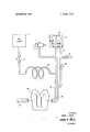
- ammonia is stored in liquid form under pressure (approximately 1 l4 p.s.i.) in a small storage canister 10 which can be fastened to the divers breathing tanks.
- the liquid ammonia passes through a control valve 12 to a heat exchanger 15 where heat absorbed from the surrounding water vaporizes the ammonia.
- the ammonia gas at the heat exchanger output is fed to an expandable bag. 21 within reservoir 20 and the input of soaker tube 28.
- the gas pressure within the bag 21 is transmitted to the water within the reservoir 20 thereby forcing the water to slowly flow through tube 19 and water control valve 26 into one end of a continuous plastic heating tube 18 which exhausts at its opposite end 30 to ambient water.
- the soaker line 28 is constructed similar to a garden soaker hose. It is a small tube closed at one end and has a surface which is uniformly perforated along its length with a series of tiny holes through which the ammonia gas can escape.
- the soaker line 28 is coaxially located within the length of the heating tube l8 so that the water flowing through the heating tube 18 passes over the surface of the soaker line 28.
- the ammonia gas escaping from the soaker line 28 comes in contact with the water flowing over its leveled, and the exothermic chemical reaction occurs throughout the heating tube 18. Heat is thereby produced uniformly over the entire length of the heating tube.
- the ammoniahydroxide produced by the chemical reaction is vented to the surrounding water through the open end 30 of the heating tube 18.
- the swimmer By placing the heating tube 18 adjacent those areas of the body requiring supplemental heat, the swimmer is provided with a uniform source of controllable heat.
- a possible arrangement is shown in the drawing where the heating tube 18 is shown located along a swimmer's vest 34 for providing heat to the chest area of the body. It should be readily apparent that the heating tube could be also located to provide heat to any area of the swimmers body or within a diving chamber.
- This system can also be used to complement use of my invention for Underwater Air Gloves" described in a copending patent application Ser. No. 761,040, filed Sept. 20, 1968 and assigned to the assignee of the instant application.
- a safety pressure relief valve 17 connected to the output of he heat exchanger 15 and is designed to operi if the ammonia gas pres sure exceeds a predetermined limit, normally around 20 p.s.i. If, for any reason the gas pressure causes the relief valve 17 to open, such as where the main control 12 is opened too wide, the audible noise of the escaping gas will provide an alarm signal to the swimmer and he can make adjustments accordingly.
- a check valve 32 is also provided on the reservoir to allow water recharging of the reservoir 20. If the system is not in use, the reservoir can be filled merely by allowing water to enter he open check valve 32 with the water control valve 26closed. Trapped air within the reservoir 0 can escape from the check valve through an inlet cap which can be provided.
- the reservoir 20 can also be recharged during operation of the system by merely turning off the ammonia flow at the main control valve 12. After the gas stored in the inflated bag 2] is absorbed by the water through the soaker line 28, the resultant reduced pressure in the reservoir will cause a rapid inward flow of water into the reservoir 20 through the check valve 32. In this manner, water recharging can take place in less than 1 minute.
- Operation of the heating system is controlled by regulating the flow of ammonia into the system with control valve 12.
- the setting of water control valve 26 remains fixed during operation thereby providing the swimmer with complete control of the system with the valve 12. If the swimmer finds himself getting cold, a simple adjustment of valve 12 to allow more ammonia into the system will provide him with additional heat.
- ammonia provides a heat of solution of about 900 b.t.u.s for every pound of ammonia vapor absorbed.
- water control valve 26 With the water control valve 26 properly set it will normally provide a mixture of roughly three parts of water to one part of ammonia by weight (at sea level). After losses to the water are accounted for, about 800 b.t.u.s are available to the swimmer for every pound of ammonia absorbed.
- the heat requirements of a swimmer in water of 29 F. runs around 1200 b.t.u.s per hour and therefore, about l /pounds of ammonia will be required to heat the swimmer every hour. Because ammonia can be supplied at about per pound and it is readily available in liquid form, the features of minimal cost and ready availability of materials are an especially attractive feature of this device.
- the total weight of a system capable of supplying heat on a 4-hour mission would be approximately 13 pounds. This includes 6 pounds of ammonia ina 1 pound storage canister, a heating garment heat exchanger water reservoir and control valves. Tests haveshown that the weight of the system is well within the limits to provide the swimmer with almost complete unrestricted freedom.
- An underwater heating system comprising:
- chemical mixing means located along said heating tube and connected to said chemical storage means to mix said chemical with the water along the length of said heating tube thereby producing heat along the heating tube as a result of an exothermic chemical reaction between said chemical and said water.
- the system of claim 1 further comprising a heat exchanger connected to the output of said chemical storage means or supplying heat to the chemical from said chemical storage means passing through said heat exchanger sufficient to change said chemical from a liquid to a gas.
- said chemical mixing means includes mixing a tube of smaller diameter than said heating tube disposed within said heating tube, said mixing tube having one end connected to receive chemical gas from said heat exchanger and the other end closed, and being uniformly perforated with a series of holes so that the chemical gas will be discharged through said holes into the water along the length of the heating tube.
- said pressure means within said reservoir is a bag connected to the output of said heat exchanger and inflatable by the chemical gas flowing therefrom so that as the bag inflates, water surrounding the bag and contained by the reservoir will be forced into said heating tube.
- An underwater heating suit to provide heat to a swimmer in cold water comprising:
- a storage tank for storing a liquid chemical
- a heating tube having one end connected to the output of said reservoir
- an inflatable bag disposed within said reservoir and connected to the output of said heat exchanger so that chemical gas from said heat exchanger will inflate the bag and force water within said reservoir into and through the heating tube;
- a mixing tube located within the heating tube and connected to the output of said heat exchanger and adapted to mix chemical gas from said heat exchanger and said inflatable bag along the length of said heating tube with the water flowing therethrough.
- the underwater heating suit of claim 6 further including a valve connected to the output of said storage tank to control the flow of liquid chemical into said heat exchanger.
- the underwater heating suit of claim 7 further including a pressure relief valve connected to the output of the heat exchanger and designed to automatically open if the pressure of the chemical gas from the heat exchanger exceeds a predetermined limit.
Landscapes
- Health & Medical Sciences (AREA)
- Vascular Medicine (AREA)
- Thermal Sciences (AREA)
- Engineering & Computer Science (AREA)
- Biomedical Technology (AREA)
- Heart & Thoracic Surgery (AREA)
- Physics & Mathematics (AREA)
- Life Sciences & Earth Sciences (AREA)
- Animal Behavior & Ethology (AREA)
- General Health & Medical Sciences (AREA)
- Public Health (AREA)
- Veterinary Medicine (AREA)
- Professional, Industrial, Or Sporting Protective Garments (AREA)
Abstract
An underwater heating system for a swimmer or diver operating in frigid underwater environments wherein the heat is produced by reacting two chemicals such as ammonia and water. The chemical reaction takes place throughout the length of a heating tube filled with water located within a swimmer''s diving suit or underwater chamber. The heat supplied to the swimmer is controlled by regulating the amount of ammonia mixing with water in the heating tube from a soaker line located within the heating tube.
Description
United States Patent [72] Inventor Daniel L. Curtis Manhattan Beach, Calif. [21] Appl. No. 825,814 [22] Filed May 19, 1969 [45] Patented Aug. 10, 1971 [73] Assignee Litton System Inc. Beverly Hills, Calif.
[54] UNDERWATER HEATING SYSTEM 9 Claims, 1 Drawing Fig.
[52] US. CL 126/204, 126/263 [51] 1nt.Cl A611 7/06, F24j 1/00 [50] Field Search 126/204. 263
[$6] Referenm Cited UNITED STATES PATENTS 1,572,975 2/ 1926 Van Meter 126/263 X 3,367,319 2/1968 Carter, Jr.
3,450,127 6/1969 Harwood, .lr. 126/204 3,474,806 10/1969 Coldren et al. 126/263 X FOREIGN PATENTS 546,1 l8 6/1942 Great Britain 126/263 Primary Examiner-Charles J. Myhre Attorneys-Alan C. Rose, Walter R. Thiel and Alfred B.
Levine ABSTRACT: An underwater heating system for a swimmer or diver operating in frigid underwater environments wherein the heat is produced by reacting two chemicals such as ammonia and water. The chemical reaction takes place throughout the length of a heating tube filled with water located within a swimmers diving suit or underwater chamber. The heat supplied to the swimmer is controlled by regulating the amount of ammonia mixing with water in the heating tube from a soaker line located within the heating tube.
PATENTEDAucmmn 3.598.103
l7 (LIQUID) IN VENTOR.
DAN/El. L. CURTIS BY a/uta A.
ATTORNEY The recent relates in underwater exploration by various research groups has emphasized the need for a self-contained lightweight and-inexpensive heating system for a swimmer to wear when submerged in cold water environments for prolonged durations.
Conventional foam neoprene wet suits provide adequate insulation where the water temperature is 50 F. or above and the swimmer is not operating at very great depths. However, wet suited swimmers operating in arctic .waters, where water temperatures approaching 29 F. may be encountered, are restricted to spending less than an hour in the water due to the numbing effect of the extreme cold. Where submersion for longer durations is required, supplemental heat must be supplied to the swimmer. In order that purpose be able to operate in an unrestricted manner, it is necessary that supplemental heat be supplied by units which are self-contained, light, and easily transportable by the swimmer.
Previously, the only effective underwater portable heating system was developed by the Navy and the Atomic Energy Commission for use in Sealab III. This system utilizes a radio isotope used in conjunction with a liquid coolant garment and a battery operated liquid pump. The cost and complexity of this unit makes it completely impractical for general purpose use. Also, because of heat losses due to the complex plumbing and heat exchanger thermal losses to the ocean, the system has to generate 30 percent more heat than reaches the man.
Other prior systems have attempted to use the heat produced by certain chemical reactions as the heat source for similarly underwater heating unit. In these systems, the chemicals are mixed at the inlet of a heating garment and the heated mix is then circulated through the garment with frangible bat tery powered pump. These systems are unsatisfactory because all the heating takes place at the point where the chemicals mix and the liquid circulated through the garment is uncomfortably hot at some parts at the expense of other parts. Additionally, there is an excessive amount flow thermal loss to the ocean because for safety reasons the chemical reaction must take place outside of the divers suit. In these suits, pump opening battery failure or a breakage at a joint in the heating garment tubing could result in severe injury or even death to the swimmer where he was operating at great depths in cold water.
It is therefore an object of this invention to provide a selfcontained heating unit to supply a uniform, controllable heat to a swimmer or pressure during prolonged submersion in cold water.
An additional object of the invention is to provide an underwater heating unit which will be self-contained, compact and lightweight.
Another object of the invention is to provide an underwater heating unit which will have a simple heat supply control and does not require a mechanical liquid pump.
Another object of the invention is to provide a self-contained underwater heating unit which is inexpensive to construct, requires minimal maintenance and operates at extremely low costs.
Another object of the invention is to provide a self-contained underwater heating unit which will quickly provide heat to a diver with high system efficiency.
SUMMARY OF THE INVENTION The ammonia is supplied in a gaseous state through a soaker tube along the length of a water-filled heating tube which is close proximity to the swimmer. The heat produced uniformly over the length of the heating tube warms the swimmer.
BRIEF DESCRIPTION OF THE DRAWINGS The specific nature of the invention, as well as samel3 objects, aspects, uses and advantages thereof, will clearly appear from the following description and from the accompanying drawing which illustrates an embodiment of my self-contained underwater heating unit in accordance with my invention.
DESCRIPTION OF THEPREFERREDEMBODIMENT The embodiment of my heating system shown in the drawing operates on the exothermic chemical reaction: NH +H O =NH4OH+ Heat. While ntherchemicals will function in a manner similar to ammonia to provide comparable heats of solution, the particular characteristics of ammonia are especially suited for a wheel system such as described herein.
As illustrated in the drawing, ammonia is stored in liquid form under pressure (approximately 1 l4 p.s.i.) in a small storage canister 10 which can be fastened to the divers breathing tanks. The liquid ammonia passes through a control valve 12 to a heat exchanger 15 where heat absorbed from the surrounding water vaporizes the ammonia. The ammonia gas at the heat exchanger output is fed to an expandable bag. 21 within reservoir 20 and the input of soaker tube 28. The gas pressure within the bag 21 is transmitted to the water within the reservoir 20 thereby forcing the water to slowly flow through tube 19 and water control valve 26 into one end of a continuous plastic heating tube 18 which exhausts at its opposite end 30 to ambient water. The soaker line 28 is constructed similar to a garden soaker hose. It is a small tube closed at one end and has a surface which is uniformly perforated along its length with a series of tiny holes through which the ammonia gas can escape. The soaker line 28 is coaxially located within the length of the heating tube l8 so that the water flowing through the heating tube 18 passes over the surface of the soaker line 28. The ammonia gas escaping from the soaker line 28 comes in contact with the water flowing over its leveled, and the exothermic chemical reaction occurs throughout the heating tube 18. Heat is thereby produced uniformly over the entire length of the heating tube. The ammoniahydroxide produced by the chemical reaction is vented to the surrounding water through the open end 30 of the heating tube 18.
By placing the heating tube 18 adjacent those areas of the body requiring supplemental heat, the swimmer is provided with a uniform source of controllable heat. A possible arrangement is shown in the drawing where the heating tube 18 is shown located along a swimmer's vest 34 for providing heat to the chest area of the body. It should be readily apparent that the heating tube could be also located to provide heat to any area of the swimmers body or within a diving chamber. This system can also be used to complement use of my invention for Underwater Air Gloves" described in a copending patent application Ser. No. 761,040, filed Sept. 20, 1968 and assigned to the assignee of the instant application.
For safety reasons the system is provided with a safety pressure relief valve 17 connected to the output of he heat exchanger 15 and is designed to operi if the ammonia gas pres sure exceeds a predetermined limit, normally around 20 p.s.i. If, for any reason the gas pressure causes the relief valve 17 to open, such as where the main control 12 is opened too wide, the audible noise of the escaping gas will provide an alarm signal to the swimmer and he can make adjustments accordingly.
A check valve 32 is also provided on the reservoir to allow water recharging of the reservoir 20. If the system is not in use, the reservoir can be filled merely by allowing water to enter he open check valve 32 with the water control valve 26closed. Trapped air within the reservoir 0 can escape from the check valve through an inlet cap which can be provided. The reservoir 20 can also be recharged during operation of the system by merely turning off the ammonia flow at the main control valve 12. After the gas stored in the inflated bag 2] is absorbed by the water through the soaker line 28, the resultant reduced pressure in the reservoir will cause a rapid inward flow of water into the reservoir 20 through the check valve 32. In this manner, water recharging can take place in less than 1 minute.
Operation of the heating system is controlled by regulating the flow of ammonia into the system with control valve 12. The setting of water control valve 26 remains fixed during operation thereby providing the swimmer with complete control of the system with the valve 12. If the swimmer finds himself getting cold, a simple adjustment of valve 12 to allow more ammonia into the system will provide him with additional heat.
One of the primary advantages to using ammonia in my system is that it provides a heat of solution of about 900 b.t.u.s for every pound of ammonia vapor absorbed. With the water control valve 26 properly set it will normally provide a mixture of roughly three parts of water to one part of ammonia by weight (at sea level). After losses to the water are accounted for, about 800 b.t.u.s are available to the swimmer for every pound of ammonia absorbed. The heat requirements of a swimmer in water of 29 F. runs around 1200 b.t.u.s per hour and therefore, about l /pounds of ammonia will be required to heat the swimmer every hour. Because ammonia can be supplied at about per pound and it is readily available in liquid form, the features of minimal cost and ready availability of materials are an especially attractive feature of this device.
Another advantage of my system is its light weight. The total weight of a system capable of supplying heat on a 4-hour mission would be approximately 13 pounds. This includes 6 pounds of ammonia ina 1 pound storage canister, a heating garment heat exchanger water reservoir and control valves. Tests haveshown that the weight of the system is well within the limits to provide the swimmer with almost complete unrestricted freedom.
From the standpoint of safety, tests have also proved that there is no tendency for the system to overheat. Additionally, the simplicity of the system coupled with the fact that all storage tanks and tube connections in the system are external to the swimmers wet suit alleviates the danger of chemical burns to the swimmer.
The only significant limitation on my system is that it is limited to an operating depth of about 175 feet due to the fact that ammonia at ocean temperatures will remain in a liquid state at a pressure equivalent to the l75-foot depth. Because the system is based upon the large increase in enthalpy, produced by vaporizing the ammonia preceding absorption by the ocean water, the system is ineffective below the specified depths.
It is to be understood that the foregoing description is directed to one embodiment ofthe invention. Various alternatives which may be employed include the reaction of chemicals which are both in a liquid state or variations in the design of the heating tube such as where the heating tube and soaker tube are adjacent rather than coaxially disposed to each other.
I claim my invention to be:
1. An underwater heating system comprising:
a. chemical storage means;
b. a heating tube adapted to have water flow therethrough,
c. a reservoir for water, said heating tube being connected to the output of said reservoir to receive 'water therefrom;
d. pressure means within said reservoir to receive a chemical from said chemical storage means and simultaneously expel water from said reservoir into said heating tube; and
e. chemical mixing means located along said heating tube and connected to said chemical storage means to mix said chemical with the water along the length of said heating tube thereby producing heat along the heating tube as a result of an exothermic chemical reaction between said chemical and said water.
2. The system of claim 1 further comprising a heat exchanger connected to the output of said chemical storage means or supplying heat to the chemical from said chemical storage means passing through said heat exchanger sufficient to change said chemical from a liquid to a gas.
3. The system of claim 2 wherein said chemical mixing means includes mixing a tube of smaller diameter than said heating tube disposed within said heating tube, said mixing tube having one end connected to receive chemical gas from said heat exchanger and the other end closed, and being uniformly perforated with a series of holes so that the chemical gas will be discharged through said holes into the water along the length of the heating tube.
4. The system of claim I wherein said pressure means within said reservoir is a bag connected to the output of said heat exchanger and inflatable by the chemical gas flowing therefrom so that as the bag inflates, water surrounding the bag and contained by the reservoir will be forced into said heating tube.
5. The apparatus of claim 1 wherein said chemical is ammonia.
6. An underwater heating suit to provide heat to a swimmer in cold water comprising:
a. a storage tank for storing a liquid chemical;
b. a heat exchanger connected to the output of said storage tank to change the chemical flowing therethrough from a liquid to a gas; 4
. a reservoir for water;
. a heating tube having one end connected to the output of said reservoir;
e. an inflatable bag disposed within said reservoir and connected to the output of said heat exchanger so that chemical gas from said heat exchanger will inflate the bag and force water within said reservoir into and through the heating tube; and
a mixing tube located within the heating tube and connected to the output of said heat exchanger and adapted to mix chemical gas from said heat exchanger and said inflatable bag along the length of said heating tube with the water flowing therethrough.
7. The underwater heating suit of claim 6 further including a valve connected to the output of said storage tank to control the flow of liquid chemical into said heat exchanger.
8. The underwater heating suit of claim 7 further including a pressure relief valve connected to the output of the heat exchanger and designed to automatically open if the pressure of the chemical gas from the heat exchanger exceeds a predetermined limit.
9. The underwater heating suit of claim 8 wherein said chemical is ammonia.
Claims (9)
1. An underwater heating system comprising: a. chemical storage means; b. a heating tube adapted to have water flow therethrough, c. a reservoir for water, said heating tube being connected to the output of said reservoir to receive water therefrom; d. pressure means within said reservoir to receive a chemical from said chemical storage means and simultaneously expel water from said reservoir into said heating tube; and e. chemical mixing means located along said heating tube and connected to said chemical storage means to mix said chemical with the water along the length of said heating tube thereby producing heat along the heating tube as a result of an exothermic chemical reaction between said chemical and said water.
2. The system of claim 1 further comprising a heat exchanger connected to the output of said chemical storage means for supplying heat to the chemical from said chemical storage means passing through said heat exchanger sufficient to change said chemical from a liquid to a gas.
3. The system of claim 2 wherein said chemical mixing means includes mixing a tube of smaller diameter than said heating tube disposed within said heating tube, said mixing tube having one end connected to receive chemical gas from said heat exchanger and the other end closed, and being uniformly perforated with a series of holes so that the chemical gas will be discharged through said holes into the water along the length of the heating tube.
4. The system of claim 1 wherein said pressure means within said reservoir is a bag connected to the output of said heat exchanger and inflatable by the chemical gas flowing therefrom so that as the bag inflates, water surrounding the bag and contained by the reservoir will be forced into said heating tube.
5. The apparatus of claim 1 wherein said chemical is ammonia.
6. An underwater heating suit to provide heat to a swimmer in cold water comprising: a. a storage tank for storing a liquid chemical; b. a heat exchanger connected to the output of said storage tank to change the chemical flowing therethrough from a liquid to a gas; c. a reservoir for water; d. a heating tube having one end connected to the output of said reservoir; e. an inflatable bag disposed within said reservoir and connected to the output of said heat exchanger so that chemical gas from said heat exchanger will inflate the bag and force water within said reservoir into and through the heating tube; and f. a mixing tube located within the heating tube and connected to the output of said heat exchanger and adapted to mix chemical gas from said heat exchanger and said inflatable bag along the length of said heating tube with the water flowing therethrough.
7. The underwater heating suit of claim 6 further including a valve connected to the output of said storage tank to control the flow of liquid chemical into said heat exchanger.
8. The underwater heating suit of claim 7 further including a pressure relief valve connected to the output of the heat exchanger and designed to automatically open if the pressure of the chemical gas from the heat exchanger exceeds a predetermined limit.
9. The underwater heating suit of claim 8 wherein said chemical is ammonia.
Applications Claiming Priority (1)
| Application Number | Priority Date | Filing Date | Title |
|---|---|---|---|
| US82581469A | 1969-05-19 | 1969-05-19 |
Publications (1)
| Publication Number | Publication Date |
|---|---|
| US3598103A true US3598103A (en) | 1971-08-10 |
Family
ID=25244983
Family Applications (1)
| Application Number | Title | Priority Date | Filing Date |
|---|---|---|---|
| US825814A Expired - Lifetime US3598103A (en) | 1969-05-19 | 1969-05-19 | Underwater heating system |
Country Status (1)
| Country | Link |
|---|---|
| US (1) | US3598103A (en) |
Cited By (2)
| Publication number | Priority date | Publication date | Assignee | Title |
|---|---|---|---|---|
| US3776775A (en) * | 1971-12-14 | 1973-12-04 | Aeroseal Corp | Removal of ice by a self-heating mixture |
| US4169499A (en) * | 1977-05-31 | 1979-10-02 | Honeywell Inc. | Solar energy heat utilization |
Citations (5)
| Publication number | Priority date | Publication date | Assignee | Title |
|---|---|---|---|---|
| US1572975A (en) * | 1922-06-05 | 1926-02-16 | James W Van Meter | Method of heating metal, glass, or other material to render the same workable |
| GB546118A (en) * | 1940-11-18 | 1942-06-29 | Simeon Samuel Clare Ellis | Improvements relating to the heating or cooling of canned foodstuffs ready for use |
| US3367319A (en) * | 1966-11-09 | 1968-02-06 | Firewel Company Inc | Apparatus for heating a diver clothed in a suit and immersed in cold water |
| US3450127A (en) * | 1968-02-26 | 1969-06-17 | Aro Of Buffalo Inc | Chemical packheater for diver's suit |
| US3474806A (en) * | 1967-09-08 | 1969-10-28 | Shell Oil Co | In situ pipeline heat generation |
-
1969
- 1969-05-19 US US825814A patent/US3598103A/en not_active Expired - Lifetime
Patent Citations (5)
| Publication number | Priority date | Publication date | Assignee | Title |
|---|---|---|---|---|
| US1572975A (en) * | 1922-06-05 | 1926-02-16 | James W Van Meter | Method of heating metal, glass, or other material to render the same workable |
| GB546118A (en) * | 1940-11-18 | 1942-06-29 | Simeon Samuel Clare Ellis | Improvements relating to the heating or cooling of canned foodstuffs ready for use |
| US3367319A (en) * | 1966-11-09 | 1968-02-06 | Firewel Company Inc | Apparatus for heating a diver clothed in a suit and immersed in cold water |
| US3474806A (en) * | 1967-09-08 | 1969-10-28 | Shell Oil Co | In situ pipeline heat generation |
| US3450127A (en) * | 1968-02-26 | 1969-06-17 | Aro Of Buffalo Inc | Chemical packheater for diver's suit |
Cited By (2)
| Publication number | Priority date | Publication date | Assignee | Title |
|---|---|---|---|---|
| US3776775A (en) * | 1971-12-14 | 1973-12-04 | Aeroseal Corp | Removal of ice by a self-heating mixture |
| US4169499A (en) * | 1977-05-31 | 1979-10-02 | Honeywell Inc. | Solar energy heat utilization |
Similar Documents
| Publication | Publication Date | Title |
|---|---|---|
| US3367319A (en) | Apparatus for heating a diver clothed in a suit and immersed in cold water | |
| US4181126A (en) | Cryogenic, underwater-breathing apparatus | |
| US6463925B2 (en) | Hot water heater for diver using hydrogen catalytic reactions | |
| US5365745A (en) | Portable life support system | |
| US3450127A (en) | Chemical packheater for diver's suit | |
| US3599625A (en) | Deep submergence heating system | |
| US3815573A (en) | Diving suit heater | |
| US3730178A (en) | Deep-sea dive suit and life support system | |
| US4294225A (en) | Diver heater system | |
| US3598103A (en) | Underwater heating system | |
| US3572314A (en) | Heated diving suit | |
| US3556205A (en) | Underwater heat generator | |
| US3648289A (en) | Deep-sea dive suit | |
| US3293851A (en) | Underwater propulsion devices | |
| US4014384A (en) | Breathing gas heater for use by a diver comprising double walled cylinder and inner container filled with hot liquid prior to use | |
| US3875924A (en) | Hydrazine fueled diver's heating system | |
| US3583386A (en) | Heating units | |
| US3831594A (en) | Life support system | |
| US4274759A (en) | Non-return hot water diving suit | |
| US3497672A (en) | Diver suit with electrical heater and fluid pump system | |
| US3670518A (en) | Garment cooling system | |
| US3107373A (en) | Inlet control for escape appliance | |
| US4119082A (en) | Subaqueous heater apparatus | |
| US4895133A (en) | Heat pack for survival in cold water | |
| US4167932A (en) | Diver heater system |