US3596968A - Lifting apparatus - Google Patents
Lifting apparatus Download PDFInfo
- Publication number
- US3596968A US3596968A US1779A US3596968DA US3596968A US 3596968 A US3596968 A US 3596968A US 1779 A US1779 A US 1779A US 3596968D A US3596968D A US 3596968DA US 3596968 A US3596968 A US 3596968A
- Authority
- US
- United States
- Prior art keywords
- lifter
- load
- frame
- motor
- lifting
- Prior art date
- Legal status (The legal status is an assumption and is not a legal conclusion. Google has not performed a legal analysis and makes no representation as to the accuracy of the status listed.)
- Expired - Lifetime
Links
Images


Classifications
-
- B—PERFORMING OPERATIONS; TRANSPORTING
- B66—HOISTING; LIFTING; HAULING
- B66C—CRANES; LOAD-ENGAGING ELEMENTS OR DEVICES FOR CRANES, CAPSTANS, WINCHES, OR TACKLES
- B66C1/00—Load-engaging elements or devices attached to lifting or lowering gear of cranes or adapted for connection therewith for transmitting lifting forces to articles or groups of articles
- B66C1/10—Load-engaging elements or devices attached to lifting or lowering gear of cranes or adapted for connection therewith for transmitting lifting forces to articles or groups of articles by mechanical means
-
- B—PERFORMING OPERATIONS; TRANSPORTING
- B66—HOISTING; LIFTING; HAULING
- B66C—CRANES; LOAD-ENGAGING ELEMENTS OR DEVICES FOR CRANES, CAPSTANS, WINCHES, OR TACKLES
- B66C13/00—Other constructional features or details
- B66C13/04—Auxiliary devices for controlling movements of suspended loads, or preventing cable slack
- B66C13/08—Auxiliary devices for controlling movements of suspended loads, or preventing cable slack for depositing loads in desired attitudes or positions
Definitions
- ABSTRACT Lifting apparatus for lifting and controlling a three-dimensional load, particularly a module for a modular building
- the apparatus includes a lifter mounted on a movable support connected to a frame.
- the lifter is adapted to be lifted by a crane or other power means
- the frame is adapted to be connected to the load as with securing lines.
- a first drive mechanism is operatively connected to the lifter for moving it relative to the support in first and second opposite directions
- a second drive mechanism is operatively connected to the support for moving the support and the lifter thereon in opposite directions perpendicular to the first and second directions.
- the drive mechanisms include electrical motors which are controlled by control apparatus operable to actuate the motors to position the lifter at any point in a plane in order to control the angle of the load while lifted.
- modules In modular construction, units of a building called modules are prebuilt in a factory in a finished or nearly finished condition, and are then transported to a site and assembled with each other to provide a complete building such as a home.
- the modules are typically transported from factory to home site on a truck, and when the truck arrives at the home site the module is lifted from the truck by means of a crane and lowered onto a foundation to which it is firmly secured.
- the module is so tilted when it is lowered onto the foundation, it becomes very difficult to set the module down on the foundation in exactly the right position; This is not to say, however, that some tilting may notbe tolerated, and in fact in some cases it is even desirable to intentionally tilt the module very slightly as it is lowered onto the foundation so as to set down first one corner, then another, and so on until the module is properly located.
- this intentional tilting requires accurate control over the angleofthe module while it is being lowered.
- Another object of the invention is to provide lifting apparatus by which a module or other load being lifted can be levelled orintentionally tilted a predetermined amount while in a raised position.
- Another object of the invention is to provide lifting apparatus in which a lifter can be positioned at any point in a predetermined plane in order to control the tilt angle of a load while lifted.
- Another object ofthe invention is to provide lifting and levelling apparatus with controls, either manually operated or automatically operated or both, for driving motors of the apparatus to accurately position a lifter relative to the center of gravity of a load.
- FIG. 1 is an elevational view showing lifting apparatus in accordance with one embodiment of the invention as used to lift a module of a home;
- FIG. 2 is an elevational view of the apparatus and module of FIG. 1 as viewed from one end;
- FIG. 3 is an elevational view of the lifting apparatus, this view being slightly larger than FIG. 2 but viewed from the same end;
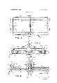
- FIG. 4 is a plan view of the lifting apparatus
- FIG. 5 is a sectional view taken along line 5-5 of FIG. 4;
- FIG. 6 is a sectional view taken along line 6-6 of FIG. 4;
- FIG. 7 is a sectional view taken along line 77 of FIG. 4;
- FIG. 8 is an enlarged sectional view of a sensing control which may be used with the apparatus
- FIG. 9 is a cross-sectional view of a gimbal used in the sensing control of FIG. 8;
- FIG. 16 is a cross-sectional view showing electrical contacts included within the sensing control of FIG. 8.
- FIG. 111 is a schematic view showing changed positions of a module while it is being levelled by means of the lifting apparatus of the invention.
- FIGS. 1 and 2 show a lifting apparatus 20 in accordance with one embodiment of the invention attached to a module 22 which is to be assembled with other modules (not shown) to form a modular home.
- the lifting; apparatus 20 is attached to the hook 24 of a crane or power lifting means which provides motive force for lifting the module 22 and lowering it as needed.
- the most critical lifting and lowering operation occurs when the module 22 is being transferred from a truck to a foundation at a home site. During this operation, the angle of the module relative to horizontal should be controlled relatively accurately, and the lifting apparatus 20 accomplishes that function.
- the lifting apparatus 20 includes a frame generally designated 26 which is attached to the module 22 by means of lines 28.
- the lines 28 may be connected directly to the module 22 at spaced points, or the lines 26 may be connected to a spreader such as the spreader 30 which is shown in FIGS. 1 and 2.
- the spreader 30 is a strong rectangular structure which absorbs the horizontal components of the lifting force applied by the lines 28 which extend at angles from the frame 26.
- the spreader 30 may be connected by short vertical lines 32 or other attachment means to studs 34 at the roof of the module 22, although a variety of attaching structures are available.
- a stud 34 is provided at each corner of the module and two additional studs 34 are provided at the midpoint of the module on opposite sides thereof.
- the lines 28 are attached to the spreader 30 at respective points directly above each of the studs 34, and the lines 28 extend angularly up to the frame 26 where they are attached to eyes 36 (FIG. 6).
- the spreader 30 receives all of the compressive forces applied by the lines 28, and in turn applies only vertical lifting forces to the module 22. If, however, the module has a strong and rigid frame as is sometimes the case, the module itself can absorb the compressive forces without damage and the spreader 30 may be omitted.
- the frame 26 is rectangular and has four I-beams 38, 40, 42 and 44 (FIG. 4).
- the I-beams 42 and 44 are joined to opposite ends ofthe I-beams 38 and 40 respectively to form the rectangular frame.
- the frame 26 is smaller in area than the module 22, but it is large enough in area to cover the zone where the center of gravity of the module 22 may be expected to lie. It is apparent that the center of gravity of the module 22 may not be at its geometrical center and, in fact, probably will not be because the structure inside the module is not uniformly distributed in most cases. Thus, the frame 26 must be large enough to allow positioning of the book 24 above the center of gravity of the module 22.
- a movable support 46 in the form of a bridge which spans the I-beams 38 and 40.
- the bridge or support 46 may also be an l-beam if desired.
- the bridge 46 has wheels or rolflanges on the inside faces of the I-beams 40 and 38, and the lower wheels 48 and the lower wheels 50' ride on the lower flanges on the inside faces of the I-beams 40 and 38.
- the two lower wheels 48 at one end of the bridge 46 are shown riding on the l-beam 40 in FIG. 6.
- the l-beams 38 and 40 are parallel to each other, and they form tracks along which the bridge 46 moves.
- the bridge 46 can move transversely in two opposite directions relative to the frame 26. Thus, the bridge 46 can traverse the full length of the frame 26.
- the lifter 50 Mounted on and connected to the bridge 46 is a lifter 50.
- the lifter 50 has an eye 52 to which the hook 24 of the crane is connected (FIG. so the lifting force of the crane is applied directly to the lifter 50.
- the lifter 50 has four wheels all designated 54, and these wheels ride on the underside of the upper flanges 56 of the l-beam which forms the bridge 46 as shown in FIGS. 5 and 6.
- the lifter 50 may consist of spaced, triangular arms 58 and 60 with the wheels 54 fastened by means of studs or the like to the lower ends of the arms 58 and 60.
- the upper ends of the arms 58 and 60 may be fastened to the eye 52.
- the lifter 50 can move longitudinally of the bridge or support 46 in two opposite directions which are perpendicular to the directions in which the bridge 46 moves.
- the lifter 50 can traverse a substantial portion of the length of the bridge 46. It may be seen that by moving the bridge 46 transversely of the frame 26 and by moving the lifter 50 longitudinally of the bridge 46, it is possible to position the lifter 50 at any desired point within a plane which corresponds generally to the plane of the frame 26. By this movement, the lifter 50, and also the hook 24 of the crane, can be positioned either directly over or in a predetermined offset position relative to the center of gravity of the module 22 for the purpose of levelling the module or for purposely tilting the module at a slight predetermined angle.
- the drive means for the bridge or support 46 includes an electrical motor 64 with a reduction gear unit 66, both of which are mounted on the l-beam 44 at one end of the frame 26.
- Two drivescrews 68 and 70 traverse the frame 26, and are journaled in bearings 72 and 74 (FIG. 7) which are mounted on the outside faces of the beams 42 and 44.
- the screws 68 and 70 have sprockets or pulleys 76 and 78 mounted on their ends, and the sprockets 76 and 78 are connected in driving relation with a sprocket 80 which is rotated by the motor 64 through the gear reduction unit 66.
- the screws 68 and 70 are operatively connected to the support or bridge 46 to provide the force for driving the bridge along the frame 26.
- the screws 68 and 70 may pass through gimbals 82 and 84.
- the screws 68 and 70 are threadedly connected to the inside ring of the gimbals 82 and 84 as shown in FIG. 5.
- the inside ring is pivotally mounted on an outside ring which is pivotally mounted on the bridge 46.
- the gimbals merely serve to take up variations in the screws which might otherwise cause the screws to bind if they were directly threadedly connected to the bridge itself or to a pillow block mounted on the bridge.
- the drive means for the lifter 50 includes a drivescrew 86 and a motor 88 which operates through a gear reduction unit 90.
- the screw 86 may be journaled at the end opposite the gear reduction unit 90 in a pillow block 92 which is mounted on the bridge 46.
- the screw 86 passes through a gimbal 94 and is threadedly connected to the inner ring of the gimbal 94.
- the inner ring is in turn pivoted on an outer ring 96 which is pivotally connected to the anus 58 and 60 of the lifter 50.
- the drivescrew 86 is operatively connected to the lifter 50 in a manner so as to provide movement of the lifter 50 along the bridge 46 in either longitudinal direction depending upon the direction of rotation of the screw 86.
- the motors 64 and 88 are reversible electrical motors to allow driving the screws in either direction of rotation.
- a manual control 100 may be connected to the motors 64 and 88 by means of cable 102.
- switches provided in the manual control 100, an operator may watch the module while it is being lifted and actuate buttons on the control 100 to drive the motors 64 and 88 so as to position the lifter 50 over the center of gravity of the module.
- the operator would observe the tilt of the module as shown in FIG. 11, and merely drive the motors to move the lifter 50 until the module is levelled as shown in dashed lines in FIG. 11.
- the movement of the lifter should be very slow so that the module does not swing back and forth in pendulum fashion when the lifter 50 is moved. This can be accomplished by proper selection of the pitch and the speed of rotation of the drivescrews and also the speed of the motors 64 and 88.
- a sensing control 104 (FIGS. 5, 6 and 8) may be provided.
- the illustrated sensing control is also a pendulum and gimbal type of device.
- a pendulum rod 106 is affixed to a ball 108 which is pivotal on stub shafts 110 and 112 which are mounted on the outer ring 114 of the gimbal.
- the outer ring 114 is in turn pivotal on stub shafts 116 and 118 which are mounted on the housing 120 of the sensing control.
- the shafts 116 and 118 may be held in place by a ring 122 which is screwed onto the housing 120 as shown in FIG. 8.
- a removable cover 124 is provided on the housing, and under this cover there are switch contacts 126, 128, and 132 as shown in FIGS. 8 and 10. These contacts are connected by appropriate wiring 134 to the motors 64 and 88.
- the contacts 126 and 130 control the motor 64, and the contacts 128 and 132 control th'emotor 88.
- the sensing control 104 may be attached to the bridge, the frame, or even directly to the module if desired.
- the movable contact 136 is centered between all of the contacts 126, 128, 130 and 132, so all control circuits are open and the motors are off. If the module 22 should tilt in the manner shown in FIG. 11 when it is lifted, the movable contact 136 would pivot into contact with the fixed contact 130, and this would actuate the motor 64 in a sense to drive the lifter 50 to the left and thus return the module to a level position as indicated in FIG. 11 in dashed lines.
- the sensing control should ordinarily be provided as a supplement to the manual control 100 and the manual control 100 could be used to override the sensing control at any time.
- the sensing control must be designed to stop the motors before the exact level condition is reached so as to prevent hunting; that is, back-and-forth operation of the motors attempting to precisely position the lifter which could result in swinging of the module.
- the manual control 100 can be used to override the sensing control 104 when it is desired to intentionally tilt the module 22 as for example when the module is being put down on a foundation. It is sometimes desirable to set one corner of a module on the foundation, then another corner, and so on until all corners are in place. This may sometimes help to accurately locate the module.
- the control 100 can be used to provide this corner-by-corner action if desired.
- the invention provides a lifting apparatus for controlling the position of a load while lifted, the apparatus being capable of either levelling the load or intentionally tilting the load slightly as needed.
- the lifter of the apparatus can be positioned at any point in a plane and not just linearly along a line.
- the device provides full levelling action.
- Lifting apparatus for lifting and controlling a threedimensional load, said apparatus including in combination, lifter means to be lifted by a power means, support means supporting said lifter means and connected thereto, first drive means operatively connected to said lifter means for moving said lifter means relative to said support means in first and second opposite directions, frame means operatively connected to said support means, means for connecting said frame means to said load, second drive means operatively connected to said support means for moving said support means and said lifter means therewith in opposite directions perpendicular to said first and second direction, said first and second drive means each including electrical motor means, and electrical control means for said motor means operable to actuate said motor means to position said lifter means at any point in a plane in order to control the angle of the load while lifted.
- said first drive means includes first screw means coupled to said lifter means and first motor means coupled to said screw means to rotate the same.
- first gimbal means couples said first screw means to said lifter means and second gimbal means couples said second screw means to said support means.
- Apparatus for lifting three-dimensional loads and for leveling the same during lifting comprising frame means, means for connecting the frame means at spaced points to the load, support means movably mounted on said frame means and movable transversely to said frame means in first and second directions, lifter means operatively connected to said support means and movable perpendicular to said first and second directions, drive means including electrical motor means to drive said support means and said lifter means, and electrical control means for said motor means operable to actuate said motor means when the load is tilted to move said lifter means to any point in a plane and thus position said lifter means over the center of gravity of the load so that force may be applied to the lifter means to lift the load in a substantially level condition.
- Lifting apparatus for lifting and controlling a threedimensional load comprising, a frame, means for attaching said frame to said load, said frame having two elongated and parallel tracks, bridge means movably mounted on said tracks and movable in first and second directions, lifter means movable with said bridge means and further movable in third and fourth directions perpendicular to said first and second directions, drive means for said lifter means and said bridge means including electrical motor means, and electrical control means for said motor means operable to actuate said motor means to position said lifter means at any point in a plane in order to control the angle of the load while lifted.
Abstract
Lifting apparatus for lifting and controlling a threedimensional load, particularly a module for a modular building. The apparatus includes a lifter mounted on a movable support connected to a frame. The lifter is adapted to be lifted by a crane or other power means. The frame is adapted to be connected to the load as with securing lines. A first drive mechanism is operatively connected to the lifter for moving it relative to the support in first and second opposite directions, and a second drive mechanism is operatively connected to the support for moving the support and the lifter thereon in opposite directions perpendicular to the first and second directions. The drive mechanisms include electrical motors which are controlled by control apparatus operable to actuate the motors to position the lifter at any point in a plane in order to control the angle of the load while lifted.
Description
United States Patent 3,413,028 11/1968 Wilkie t.
ABSTRACT: Lifting apparatus for lifting and controlling a three-dimensional load, particularly a module for a modular building The apparatus includes a lifter mounted on a movable support connected to a frame. The lifter is adapted to be lifted by a crane or other power means The frame is adapted to be connected to the load as with securing lines. A first drive mechanism is operatively connected to the lifter for moving it relative to the support in first and second opposite directions, and a second drive mechanism is operatively connected to the support for moving the support and the lifter thereon in opposite directions perpendicular to the first and second directions. The drive mechanisms include electrical motors which are controlled by control apparatus operable to actuate the motors to position the lifter at any point in a plane in order to control the angle of the load while lifted.
PATENTEU Aus sum 3; 596,968
sum 1 0F 3 INVENTOR JOHN J. HOLM 2 SETTLE & OLTMAN ATTORNEYS PATENTEDAUE 3m $599 968 sum 2 OF 3 46 I JOHP J JHOLIVI 104 SETTLE & OLTMAN ATTORNEYS PATENTED Am; 3 l9?! SHEET 3 OF 3 INVENTOR JOHN J. HOL M SETTLE & OLTMAN AT TORNEYS LIFTING APPARATUS Modular construction offers many advantages to the home builder and builders of other types of buildings as well. To name a few, standardized materials can be used, structures and shapes can be prefabricated to relatively exact dimensions within close tolerances to assure proper fit. The time required for construction can be greatly reduced, and economies in labor and materials can be achieved.
In modular construction, units of a building called modules are prebuilt in a factory in a finished or nearly finished condition, and are then transported to a site and assembled with each other to provide a complete building such as a home. The modules are typically transported from factory to home site on a truck, and when the truck arrives at the home site the module is lifted from the truck by means of a crane and lowered onto a foundation to which it is firmly secured.
Lifting a heavy home module which may weigh several tons and lowering it into an exact position on a foundation while the module is suspended from a crane offers some practical problems. The exact location of the center of gravity of the module varies from one module to another, partly because of model variations, so the line of the crane cannot ordinarily be attached directly over the center of gravity of the module. Even a slight variation from the center of gravity may result in tilting of the module when it is lifted. If the module is so tilted when it is lowered onto the foundation, it becomes very difficult to set the module down on the foundation in exactly the right position; This is not to say, however, that some tilting may notbe tolerated, and in fact in some cases it is even desirable to intentionally tilt the module very slightly as it is lowered onto the foundation so as to set down first one corner, then another, and so on until the module is properly located. However this intentional tilting requires accurate control over the angleofthe module while it is being lowered.
Accordingly, it is an object of the present invention to provide lifting apparatus for lifting and controlling the angle of a three-dimensional load such as a module for a modular building.
Another object of the invention is to provide lifting apparatus by which a module or other load being lifted can be levelled orintentionally tilted a predetermined amount while in a raised position.
Another object of the invention is to provide lifting apparatus in which a lifter can be positioned at any point in a predetermined plane in order to control the tilt angle of a load while lifted.
Another object ofthe invention is to provide lifting and levelling apparatus with controls, either manually operated or automatically operated or both, for driving motors of the apparatus to accurately position a lifter relative to the center of gravity of a load.
Among the other objects of the invention are to provide lift ing apparatus which can be fabricated on a practical basis, which is not critical in operation, which is not unduly expensive, and which can be operated in conjunction with a crane or other power means without critically sensitive manipulation.
Other objects of this invention will appear from the following description and appended claims, reference being had to the accompanying drawings forming a part of this specification wherein like reference characters designate corresponding parts in the several views.
ON THE DRAWINGS FIG. 1 is an elevational view showing lifting apparatus in accordance with one embodiment of the invention as used to lift a module of a home;
FIG. 2 is an elevational view of the apparatus and module of FIG. 1 as viewed from one end;
FIG. 3 is an elevational view of the lifting apparatus, this view being slightly larger than FIG. 2 but viewed from the same end;
FIG. 4 is a plan view of the lifting apparatus;
FIG. 5 is a sectional view taken along line 5-5 of FIG. 4;
FIG. 6 is a sectional view taken along line 6-6 of FIG. 4;
FIG. 7 is a sectional view taken along line 77 of FIG. 4;
FIG. 8 is an enlarged sectional view of a sensing control which may be used with the apparatus;
FIG. 9 is a cross-sectional view of a gimbal used in the sensing control of FIG. 8;
FIG. 16 is a cross-sectional view showing electrical contacts included within the sensing control of FIG. 8; and
FIG. 111 is a schematic view showing changed positions of a module while it is being levelled by means of the lifting apparatus of the invention.
Before explaining the present invention in detail, it is to be understood that the invention is not limited in its application to the details of construction and arrangement of parts illustrated in the accompanying drawings, since the invention is capable of other embodiments and of being practiced or carried out in various ways. Also, it is to be understood that the phraseology or terminology employed herein is for the purpose of description and not of limitation.
AS SHOWN ON THE DRAWINGS FIGS. 1 and 2 show a lifting apparatus 20 in accordance with one embodiment of the invention attached to a module 22 which is to be assembled with other modules (not shown) to form a modular home. The lifting; apparatus 20 is attached to the hook 24 of a crane or power lifting means which provides motive force for lifting the module 22 and lowering it as needed. As previously mentioned, the most critical lifting and lowering operation occurs when the module 22 is being transferred from a truck to a foundation at a home site. During this operation, the angle of the module relative to horizontal should be controlled relatively accurately, and the lifting apparatus 20 accomplishes that function.
The lifting apparatus 20 includes a frame generally designated 26 which is attached to the module 22 by means of lines 28. The lines 28 may be connected directly to the module 22 at spaced points, or the lines 26 may be connected to a spreader such as the spreader 30 which is shown in FIGS. 1 and 2. The spreader 30 is a strong rectangular structure which absorbs the horizontal components of the lifting force applied by the lines 28 which extend at angles from the frame 26. As shown in FIGS. l and 2, the spreader 30 may be connected by short vertical lines 32 or other attachment means to studs 34 at the roof of the module 22, although a variety of attaching structures are available. In the drawings, a stud 34 is provided at each corner of the module and two additional studs 34 are provided at the midpoint of the module on opposite sides thereof. The lines 28 are attached to the spreader 30 at respective points directly above each of the studs 34, and the lines 28 extend angularly up to the frame 26 where they are attached to eyes 36 (FIG. 6). Thus, the spreader 30 receives all of the compressive forces applied by the lines 28, and in turn applies only vertical lifting forces to the module 22. If, however, the module has a strong and rigid frame as is sometimes the case, the module itself can absorb the compressive forces without damage and the spreader 30 may be omitted.
In the illustrated embodiment, the frame 26 is rectangular and has four I- beams 38, 40, 42 and 44 (FIG. 4). The I- beams 42 and 44 are joined to opposite ends ofthe I- beams 38 and 40 respectively to form the rectangular frame. The frame 26 is smaller in area than the module 22, but it is large enough in area to cover the zone where the center of gravity of the module 22 may be expected to lie. It is apparent that the center of gravity of the module 22 may not be at its geometrical center and, in fact, probably will not be because the structure inside the module is not uniformly distributed in most cases. Thus, the frame 26 must be large enough to allow positioning of the book 24 above the center of gravity of the module 22.
Mounted on and connected to the frame 26 is a movable support 46 in the form of a bridge which spans the I- beams 38 and 40. The bridge or support 46 may also be an l-beam if desired. As shown in FIG. 5, the bridge 46 has wheels or rolflanges on the inside faces of the I- beams 40 and 38, and the lower wheels 48 and the lower wheels 50' ride on the lower flanges on the inside faces of the I- beams 40 and 38. The two lower wheels 48 at one end of the bridge 46 are shown riding on the l-beam 40 in FIG. 6. The l- beams 38 and 40 are parallel to each other, and they form tracks along which the bridge 46 moves. The bridge 46 can move transversely in two opposite directions relative to the frame 26. Thus, the bridge 46 can traverse the full length of the frame 26.
Mounted on and connected to the bridge 46 is a lifter 50. The lifter 50 has an eye 52 to which the hook 24 of the crane is connected (FIG. so the lifting force of the crane is applied directly to the lifter 50. The lifter 50 has four wheels all designated 54, and these wheels ride on the underside of the upper flanges 56 of the l-beam which forms the bridge 46 as shown in FIGS. 5 and 6.
The lifter 50 may consist of spaced, triangular arms 58 and 60 with the wheels 54 fastened by means of studs or the like to the lower ends of the arms 58 and 60. The upper ends of the arms 58 and 60 may be fastened to the eye 52.
The lifter 50 can move longitudinally of the bridge or support 46 in two opposite directions which are perpendicular to the directions in which the bridge 46 moves. The lifter 50 can traverse a substantial portion of the length of the bridge 46. It may be seen that by moving the bridge 46 transversely of the frame 26 and by moving the lifter 50 longitudinally of the bridge 46, it is possible to position the lifter 50 at any desired point within a plane which corresponds generally to the plane of the frame 26. By this movement, the lifter 50, and also the hook 24 of the crane, can be positioned either directly over or in a predetermined offset position relative to the center of gravity of the module 22 for the purpose of levelling the module or for purposely tilting the module at a slight predetermined angle.
The drive means for the bridge or support 46 includes an electrical motor 64 with a reduction gear unit 66, both of which are mounted on the l-beam 44 at one end of the frame 26. Two drivescrews 68 and 70 traverse the frame 26, and are journaled in bearings 72 and 74 (FIG. 7) which are mounted on the outside faces of the beams 42 and 44. The screws 68 and 70 have sprockets or pulleys 76 and 78 mounted on their ends, and the sprockets 76 and 78 are connected in driving relation with a sprocket 80 which is rotated by the motor 64 through the gear reduction unit 66.
The screws 68 and 70 are operatively connected to the support or bridge 46 to provide the force for driving the bridge along the frame 26. The screws 68 and 70 may pass through gimbals 82 and 84. The screws 68 and 70 are threadedly connected to the inside ring of the gimbals 82 and 84 as shown in FIG. 5. The inside ring is pivotally mounted on an outside ring which is pivotally mounted on the bridge 46. The gimbals merely serve to take up variations in the screws which might otherwise cause the screws to bind if they were directly threadedly connected to the bridge itself or to a pillow block mounted on the bridge.
The drive means for the lifter 50 includes a drivescrew 86 and a motor 88 which operates through a gear reduction unit 90. The screw 86 may be journaled at the end opposite the gear reduction unit 90 in a pillow block 92 which is mounted on the bridge 46. The screw 86 passes through a gimbal 94 and is threadedly connected to the inner ring of the gimbal 94. The inner ring is in turn pivoted on an outer ring 96 which is pivotally connected to the anus 58 and 60 of the lifter 50. Thus, the drivescrew 86 is operatively connected to the lifter 50 in a manner so as to provide movement of the lifter 50 along the bridge 46 in either longitudinal direction depending upon the direction of rotation of the screw 86. Of course the motors 64 and 88 are reversible electrical motors to allow driving the screws in either direction of rotation.
As shown in FIG. 1, a manual control 100 may be connected to the motors 64 and 88 by means of cable 102. By means of switches provided in the manual control 100, an operator may watch the module while it is being lifted and actuate buttons on the control 100 to drive the motors 64 and 88 so as to position the lifter 50 over the center of gravity of the module. Actually, the operator would observe the tilt of the module as shown in FIG. 11, and merely drive the motors to move the lifter 50 until the module is levelled as shown in dashed lines in FIG. 11. The movement of the lifter should be very slow so that the module does not swing back and forth in pendulum fashion when the lifter 50 is moved. This can be accomplished by proper selection of the pitch and the speed of rotation of the drivescrews and also the speed of the motors 64 and 88.
In addition to the manual control 100, or perhaps as an alternative thereto, a sensing control 104 (FIGS. 5, 6 and 8) may be provided. The illustrated sensing control is also a pendulum and gimbal type of device. A pendulum rod 106 is affixed to a ball 108 which is pivotal on stub shafts 110 and 112 which are mounted on the outer ring 114 of the gimbal. The outer ring 114 is in turn pivotal on stub shafts 116 and 118 which are mounted on the housing 120 of the sensing control. The shafts 116 and 118 may be held in place by a ring 122 which is screwed onto the housing 120 as shown in FIG. 8. A removable cover 124 is provided on the housing, and under this cover there are switch contacts 126, 128, and 132 as shown in FIGS. 8 and 10. These contacts are connected by appropriate wiring 134 to the motors 64 and 88. The contacts 126 and 130 control the motor 64, and the contacts 128 and 132 control th'emotor 88. On top of the ball or inner ring 108 of the gimbal of the sensing control is a movable contact 136.
As may be seen in FIGS. 5 and 6, the sensing control 104 may be attached to the bridge, the frame, or even directly to the module if desired. When the element to which the sensing control is attached is horizontal, the movable contact 136 is centered between all of the contacts 126, 128, 130 and 132, so all control circuits are open and the motors are off. If the module 22 should tilt in the manner shown in FIG. 11 when it is lifted, the movable contact 136 would pivot into contact with the fixed contact 130, and this would actuate the motor 64 in a sense to drive the lifter 50 to the left and thus return the module to a level position as indicated in FIG. 11 in dashed lines.
The sensing control should ordinarily be provided as a supplement to the manual control 100 and the manual control 100 could be used to override the sensing control at any time. The sensing control must be designed to stop the motors before the exact level condition is reached so as to prevent hunting; that is, back-and-forth operation of the motors attempting to precisely position the lifter which could result in swinging of the module. It will be understood that the manual control 100 can be used to override the sensing control 104 when it is desired to intentionally tilt the module 22 as for example when the module is being put down on a foundation. It is sometimes desirable to set one corner of a module on the foundation, then another corner, and so on until all corners are in place. This may sometimes help to accurately locate the module. The control 100 can be used to provide this corner-by-corner action if desired.
Thus, the invention provides a lifting apparatus for controlling the position of a load while lifted, the apparatus being capable of either levelling the load or intentionally tilting the load slightly as needed. The lifter of the apparatus can be positioned at any point in a plane and not just linearly along a line. Thus, the device provides full levelling action.
Having thus described my invention, I claim:
1. Lifting apparatus for lifting and controlling a threedimensional load, said apparatus including in combination, lifter means to be lifted by a power means, support means supporting said lifter means and connected thereto, first drive means operatively connected to said lifter means for moving said lifter means relative to said support means in first and second opposite directions, frame means operatively connected to said support means, means for connecting said frame means to said load, second drive means operatively connected to said support means for moving said support means and said lifter means therewith in opposite directions perpendicular to said first and second direction, said first and second drive means each including electrical motor means, and electrical control means for said motor means operable to actuate said motor means to position said lifter means at any point in a plane in order to control the angle of the load while lifted.
2. The lifting apparatus as claimed in claim 1 in which said first drive means includes first screw means coupled to said lifter means and first motor means coupled to said screw means to rotate the same.
3. The lifting apparatus as claimed in claim 2 in which said second drive means includes second screw means coupled to said support means and second motor means coupled to said second screw means to rotate the same.
4. The lifting apparatus as claimed in claim 3 in which first gimbal means couples said first screw means to said lifter means and second gimbal means couples said second screw means to said support means.
5. The lifting apparatus as claimed in claim 4 in which said frame means has tracks thereon, and said support means has wheels riding on said tracks to provide movement in said directions.
6. The lifting apparatus as claimed in claim 5 in which said support means has tracks thereon, and said lifter means has wheels riding on said tracks to provide movement in said opposite directions.
7. The lifting apparatus as claimed in claim 1 in which said electrical control means includes a sensing. means for sensing the angle of the load to automatically actuate said motor means.
8. Apparatus for lifting three-dimensional loads and for leveling the same during lifting, said apparatus comprising frame means, means for connecting the frame means at spaced points to the load, support means movably mounted on said frame means and movable transversely to said frame means in first and second directions, lifter means operatively connected to said support means and movable perpendicular to said first and second directions, drive means including electrical motor means to drive said support means and said lifter means, and electrical control means for said motor means operable to actuate said motor means when the load is tilted to move said lifter means to any point in a plane and thus position said lifter means over the center of gravity of the load so that force may be applied to the lifter means to lift the load in a substantially level condition.
9. Lifting apparatus for lifting and controlling a threedimensional load comprising, a frame, means for attaching said frame to said load, said frame having two elongated and parallel tracks, bridge means movably mounted on said tracks and movable in first and second directions, lifter means movable with said bridge means and further movable in third and fourth directions perpendicular to said first and second directions, drive means for said lifter means and said bridge means including electrical motor means, and electrical control means for said motor means operable to actuate said motor means to position said lifter means at any point in a plane in order to control the angle of the load while lifted.
10. Lifting apparatus for lifting and leveling a three-dimensional load comprising, a frame having a pair of spaced and parallel tracks, means for attaching said frame to said load at spaced points, a bridge having wheels riding on said tracks and movable in two opposite directions, a motor, screw means coupling said motor to said bridge for driving said bridge, said bridge having a track at right angles to said tracks of said frame, a lifter having wheels riding on said track of said bridge, another motor, and further screw means coupling said other motor to said lifter for driving said lifter in directions perpendicular to said opposite directions, said lifter being adapted to be coupled to a crane or the like to lift a load and leveling the load by operation of said motors to place the lifter over the center ofgravity of the load.
Claims (10)
1. Lifting apparatus for lifting and controlling a threedimensional load, said apparatus including in combination, lifter means to be lifted by a power means, support means supporting said lifter means and connected thereto, first drive means operatively connected to said lifter means for moving said lifter means relative to said support means in first and second opposite directions, frame means operatively connected to said support means, means for connecting said frame means to said load, second drive means operatively connected to said support means for moving said support means and said lifter means therewith in opposite directions perpendicular to said first and second directions, said first and second drive means each including electrical motor means, and electrical control means for said motor means operable to actuate said motor means to position said lifter means at any point in a plane in order to control the angle of the load while lifted.
2. The lifting apparatus as claimed in claim 1 in which said first drive means includes first screw means coupled to said lifter means and first motor means coupled to said screw means to rotate the same.
3. The lifting apparatus as claimed in claim 2 in which said second drive means includes second screw means coupled to said support means and second motor means coupled to said second screw means to rotate the same.
4. The lifting apparatus as claimed in claim 3 in which first gimbal means couples said first screw means to said lifter means and second gimbal means couples said second screw means to said support means.
5. The lifting apparatus as claimed in claim 4 in which said frame means has tracks thereon, and said support means has wheels riding on said tracks to provide movement in said directions.
6. The lifting apparatus as claimed in claim 5 in which said support means has tracks thereon, and said lifter means has wheels riding on said tracks to provide movement in said opposite directions.
7. The lifting apparatus as claimed in claim 1 in which said electrical control means includes a sensing means for sensing the angle of the load to automatically actuate said motor means.
8. APparatus for lifting three-dimensional loads and for leveling the same during lifting, said apparatus comprising frame means, means for connecting the frame means at spaced points to the load, support means movably mounted on said frame means and movable transversely to said frame means in first and second directions, lifter means operatively connected to said support means and movable perpendicular to said first and second directions, drive means including electrical motor means to drive said support means and said lifter means, and electrical control means for said motor means operable to actuate said motor means when the load is tilted to move said lifter means to any point in a plane and thus position said lifter means over the center of gravity of the load so that force may be applied to the lifter means to lift the load in a substantially level condition.
9. Lifting apparatus for lifting and controlling a three-dimensional load comprising, a frame, means for attaching said frame to said load, said frame having two elongated and parallel tracks, bridge means movably mounted on said tracks and movable in first and second directions, lifter means movable with said bridge means and further movable in third and fourth directions perpendicular to said first and second directions, drive means for said lifter means and said bridge means including electrical motor means, and electrical control means for said motor means operable to actuate said motor means to position said lifter means at any point in a plane in order to control the angle of the load while lifted.
10. Lifting apparatus for lifting and leveling a three-dimensional load comprising, a frame having a pair of spaced and parallel tracks, means for attaching said frame to said load at spaced points, a bridge having wheels riding on said tracks and movable in two opposite directions, a motor, screw means coupling said motor to said bridge for driving said bridge, said bridge having a track at right angles to said tracks of said frame, a lifter having wheels riding on said track of said bridge, another motor, and further screw means coupling said other motor to said lifter for driving said lifter in directions perpendicular to said opposite directions, said lifter being adapted to be coupled to a crane or the like to lift a load and leveling the load by operation of said motors to place the lifter over the center of gravity of the load.
Applications Claiming Priority (1)
| Application Number | Priority Date | Filing Date | Title |
|---|---|---|---|
| US177970A | 1970-01-09 | 1970-01-09 |
Publications (1)
| Publication Number | Publication Date |
|---|---|
| US3596968A true US3596968A (en) | 1971-08-03 |
Family
ID=21697803
Family Applications (1)
| Application Number | Title | Priority Date | Filing Date |
|---|---|---|---|
| US1779A Expired - Lifetime US3596968A (en) | 1970-01-09 | 1970-01-09 | Lifting apparatus |
Country Status (1)
| Country | Link |
|---|---|
| US (1) | US3596968A (en) |
Cited By (32)
| Publication number | Priority date | Publication date | Assignee | Title |
|---|---|---|---|---|
| US3722170A (en) * | 1971-01-13 | 1973-03-27 | Treadwell Corp | Method of hoisting and anchoring heavy structures in a building |
| US3837698A (en) * | 1971-07-29 | 1974-09-24 | Crc Crose Int Inc | Lifting apparatus |
| US3958824A (en) * | 1973-09-21 | 1976-05-25 | Westinghouse Electric Corporation | Lifting frame and methods of lifting prefabricated building modules |
| FR2402615A1 (en) * | 1977-09-09 | 1979-04-06 | Brissonneau & Lotz | CONTAINER OR SIMILAR GRIPPING DEVICE |
| EP0041290A2 (en) * | 1980-05-20 | 1981-12-09 | Ihc Holland N.V. | Hoisting yoke |
| US4381166A (en) * | 1980-10-27 | 1983-04-26 | Smart Robert L | Fork unit having adjustable forks |
| US4671721A (en) * | 1984-03-12 | 1987-06-09 | Rodger Pratt | Apparatus and method for positioning an object in a building |
| US4831967A (en) * | 1987-12-31 | 1989-05-23 | Anderson Charles D | Animal lift frame |
| US4936616A (en) * | 1989-08-21 | 1990-06-26 | Williams William M | Engine tilting device |
| US4973094A (en) * | 1988-09-27 | 1990-11-27 | Marinestar Nautica Di Tana Guido & C. S.N.C. | Crane implement for hoisting and launching boats to and from a quay |
| WO1991006446A1 (en) * | 1989-10-24 | 1991-05-16 | Edwards Lawrence K | Passenger car with emergency exit |
| US5205544A (en) * | 1991-03-01 | 1993-04-27 | Kroeger Donald E | Remotely controlled winch |
| FR2746783A1 (en) * | 1996-03-27 | 1997-10-03 | Fontanel Robert | Balanced support for lifting loads |
| WO2000073194A1 (en) * | 1999-05-28 | 2000-12-07 | Uti Holding + Management Ag | Cross beam for lifting a loaded item |
| WO2002010055A3 (en) * | 2000-07-29 | 2002-09-06 | B & P Bautraeger Gmbh | Device for transporting and lifting bulky objects |
| US6920721B2 (en) | 2002-06-05 | 2005-07-26 | Adv-Tech Building Systems, Llc | Building system |
| US20060065773A1 (en) * | 2004-09-27 | 2006-03-30 | Grant Chad W | Systems and methods for rotation of objects |
| US20070080549A1 (en) * | 2005-10-07 | 2007-04-12 | Jenney Alfred P | Leveling device for lifting apparatus and associated methods |
| US20080131248A1 (en) * | 2006-12-01 | 2008-06-05 | Lockheed Martin Corporation | Center of gravity sensing and adjusting load bar, program product, and related methods |
| US20080129065A1 (en) * | 2006-11-30 | 2008-06-05 | Alway Vern J | Self-adjusting load bar |
| WO2009042000A1 (en) * | 2007-09-28 | 2009-04-02 | Heinaman Contract Glazing, Inc. | Device for lifting and moving window frames |
| US20130028699A1 (en) * | 2011-07-27 | 2013-01-31 | General Electric Company | System and method for supporting a shaft inside a turbine |
| US20140246875A1 (en) * | 2012-09-21 | 2014-09-04 | Pcl Industrial Management Inc. | Adjustable module lift frame assembly |
| US8979148B1 (en) * | 2013-03-07 | 2015-03-17 | II Gary Michael Hatton | Fly jib for a crane and method of use |
| CN105712177A (en) * | 2014-12-19 | 2016-06-29 | 空中客车防务和空间公司 | Device for hoisting and controlling loads |
| US20170247875A1 (en) * | 2015-12-09 | 2017-08-31 | National Taiwan University | Autonomous beam assembly system for steel structure |
| AU2014201893B2 (en) * | 2013-04-05 | 2018-08-16 | Metso Outotec USA Inc. | Device and method for handling a liner element of a grinding mill |
| US10077168B2 (en) * | 2014-05-07 | 2018-09-18 | The Caldwell Group, Inc. | Automatic leveling device with adjustable orientation setting |
| US11130657B2 (en) * | 2019-03-29 | 2021-09-28 | Joel FORMOSA | Apparatus for adjusting an orientation of a suspended load |
| US20220033231A1 (en) * | 2020-08-03 | 2022-02-03 | Toyota Motor Engineering & Manufacturing North America, Inc. | Adjustable load leveler apparatus and related methods for use with automotive manufacturing systems |
| US11286046B2 (en) * | 2018-03-26 | 2022-03-29 | Michael J. Capek | Payload lift and positioning system for airships |
| US11654989B2 (en) * | 2019-04-11 | 2023-05-23 | Hall Labs Llc | Load leveling hanger |
Citations (2)
| Publication number | Priority date | Publication date | Assignee | Title |
|---|---|---|---|---|
| US3191983A (en) * | 1963-11-06 | 1965-06-29 | Nat Castings Co | Self-leveling cargo container spreader |
| US3413028A (en) * | 1966-10-07 | 1968-11-26 | Sun Shipbuilding & Dry Dock Co | Load equalizer |
-
1970
- 1970-01-09 US US1779A patent/US3596968A/en not_active Expired - Lifetime
Patent Citations (2)
| Publication number | Priority date | Publication date | Assignee | Title |
|---|---|---|---|---|
| US3191983A (en) * | 1963-11-06 | 1965-06-29 | Nat Castings Co | Self-leveling cargo container spreader |
| US3413028A (en) * | 1966-10-07 | 1968-11-26 | Sun Shipbuilding & Dry Dock Co | Load equalizer |
Cited By (50)
| Publication number | Priority date | Publication date | Assignee | Title |
|---|---|---|---|---|
| US3722170A (en) * | 1971-01-13 | 1973-03-27 | Treadwell Corp | Method of hoisting and anchoring heavy structures in a building |
| US3837698A (en) * | 1971-07-29 | 1974-09-24 | Crc Crose Int Inc | Lifting apparatus |
| US3958824A (en) * | 1973-09-21 | 1976-05-25 | Westinghouse Electric Corporation | Lifting frame and methods of lifting prefabricated building modules |
| FR2402615A1 (en) * | 1977-09-09 | 1979-04-06 | Brissonneau & Lotz | CONTAINER OR SIMILAR GRIPPING DEVICE |
| EP0041290A2 (en) * | 1980-05-20 | 1981-12-09 | Ihc Holland N.V. | Hoisting yoke |
| EP0041290A3 (en) * | 1980-05-20 | 1981-12-16 | Ihc Holland N.V. | Hoisting yoke |
| US4394041A (en) * | 1980-05-20 | 1983-07-19 | Ihc Holland N.V. | Hoisting yoke |
| US4381166A (en) * | 1980-10-27 | 1983-04-26 | Smart Robert L | Fork unit having adjustable forks |
| US4671721A (en) * | 1984-03-12 | 1987-06-09 | Rodger Pratt | Apparatus and method for positioning an object in a building |
| US4831967A (en) * | 1987-12-31 | 1989-05-23 | Anderson Charles D | Animal lift frame |
| US4973094A (en) * | 1988-09-27 | 1990-11-27 | Marinestar Nautica Di Tana Guido & C. S.N.C. | Crane implement for hoisting and launching boats to and from a quay |
| US4936616A (en) * | 1989-08-21 | 1990-06-26 | Williams William M | Engine tilting device |
| WO1991006446A1 (en) * | 1989-10-24 | 1991-05-16 | Edwards Lawrence K | Passenger car with emergency exit |
| US5205544A (en) * | 1991-03-01 | 1993-04-27 | Kroeger Donald E | Remotely controlled winch |
| FR2746783A1 (en) * | 1996-03-27 | 1997-10-03 | Fontanel Robert | Balanced support for lifting loads |
| WO2000073194A1 (en) * | 1999-05-28 | 2000-12-07 | Uti Holding + Management Ag | Cross beam for lifting a loaded item |
| WO2002010055A3 (en) * | 2000-07-29 | 2002-09-06 | B & P Bautraeger Gmbh | Device for transporting and lifting bulky objects |
| US6920721B2 (en) | 2002-06-05 | 2005-07-26 | Adv-Tech Building Systems, Llc | Building system |
| US20060065773A1 (en) * | 2004-09-27 | 2006-03-30 | Grant Chad W | Systems and methods for rotation of objects |
| WO2006078330A2 (en) * | 2004-09-27 | 2006-07-27 | L-3 Integrated Systems Company | Systems and methods for rotation of objects |
| US7708325B2 (en) * | 2004-09-27 | 2010-05-04 | L-3 Communications Integrated Systems L.P. | Systems and methods for rotation of objects |
| WO2006078330A3 (en) * | 2004-09-27 | 2008-12-04 | L 3 Integrated Systems Co | Systems and methods for rotation of objects |
| US7455338B2 (en) * | 2005-10-07 | 2008-11-25 | Jenney Alfred P | Leveling device for lifting apparatus and associated methods |
| US20070080549A1 (en) * | 2005-10-07 | 2007-04-12 | Jenney Alfred P | Leveling device for lifting apparatus and associated methods |
| US20080129065A1 (en) * | 2006-11-30 | 2008-06-05 | Alway Vern J | Self-adjusting load bar |
| US7931320B2 (en) | 2006-11-30 | 2011-04-26 | Innovation Egineering, Inc. | Self-adjusting load bar |
| US20080131248A1 (en) * | 2006-12-01 | 2008-06-05 | Lockheed Martin Corporation | Center of gravity sensing and adjusting load bar, program product, and related methods |
| US8000835B2 (en) | 2006-12-01 | 2011-08-16 | Lockheed Martin Corporation | Center of gravity sensing and adjusting load bar, program product, and related methods |
| EP1930289A3 (en) * | 2006-12-01 | 2013-07-10 | Lockheed Martin Corporation | Center of gravity sensing and adjusting load bar, program product, and related methods |
| WO2009042000A1 (en) * | 2007-09-28 | 2009-04-02 | Heinaman Contract Glazing, Inc. | Device for lifting and moving window frames |
| US20090084747A1 (en) * | 2007-09-28 | 2009-04-02 | Mark Heinaman | Device for lifting and moving window frames |
| US20110036043A1 (en) * | 2007-09-28 | 2011-02-17 | Mark Heinaman | Device for lifting and moving window frames |
| US7891718B2 (en) | 2007-09-28 | 2011-02-22 | Heinaman Contract Glazing, Inc. | Device for lifting and moving window frames |
| US20130028699A1 (en) * | 2011-07-27 | 2013-01-31 | General Electric Company | System and method for supporting a shaft inside a turbine |
| US8789866B2 (en) * | 2011-07-27 | 2014-07-29 | General Electric Company | System and method for supporting a shaft inside a turbine |
| US20140246875A1 (en) * | 2012-09-21 | 2014-09-04 | Pcl Industrial Management Inc. | Adjustable module lift frame assembly |
| US9399564B2 (en) | 2012-09-21 | 2016-07-26 | Pcl Industrial Management Inc. | Adjustable module lift frame assembly |
| US9463959B2 (en) * | 2012-09-21 | 2016-10-11 | Pcl Industrial Management Inc. | Adjustable module lift frame assembly |
| US8979148B1 (en) * | 2013-03-07 | 2015-03-17 | II Gary Michael Hatton | Fly jib for a crane and method of use |
| AU2014201893B2 (en) * | 2013-04-05 | 2018-08-16 | Metso Outotec USA Inc. | Device and method for handling a liner element of a grinding mill |
| US10077168B2 (en) * | 2014-05-07 | 2018-09-18 | The Caldwell Group, Inc. | Automatic leveling device with adjustable orientation setting |
| CN105712177A (en) * | 2014-12-19 | 2016-06-29 | 空中客车防务和空间公司 | Device for hoisting and controlling loads |
| US10106376B2 (en) | 2014-12-19 | 2018-10-23 | Airbus Defence And Space, S.A. | Device for hoisting and controlling loads |
| CN105712177B (en) * | 2014-12-19 | 2019-06-18 | 空中客车防务和空间公司 | Equipment for promoting and controlling load |
| US20170247875A1 (en) * | 2015-12-09 | 2017-08-31 | National Taiwan University | Autonomous beam assembly system for steel structure |
| US11286046B2 (en) * | 2018-03-26 | 2022-03-29 | Michael J. Capek | Payload lift and positioning system for airships |
| US11130657B2 (en) * | 2019-03-29 | 2021-09-28 | Joel FORMOSA | Apparatus for adjusting an orientation of a suspended load |
| US11654989B2 (en) * | 2019-04-11 | 2023-05-23 | Hall Labs Llc | Load leveling hanger |
| US20220033231A1 (en) * | 2020-08-03 | 2022-02-03 | Toyota Motor Engineering & Manufacturing North America, Inc. | Adjustable load leveler apparatus and related methods for use with automotive manufacturing systems |
| US11738974B2 (en) * | 2020-08-03 | 2023-08-29 | Toyota Motor Engineering & Manufacturing North Inc. | Adjustable load leveler apparatus and related methods for use with automotive manufacturing systems |
Similar Documents
| Publication | Publication Date | Title |
|---|---|---|
| US3596968A (en) | Lifting apparatus | |
| CA2088511C (en) | Platform leveling apparatus | |
| US3709322A (en) | Overhead service apparatus with swivel platform | |
| US4648647A (en) | Load handling apparatus | |
| US3545627A (en) | Heavy duty crane for use in a narrow loading area | |
| EP1064215B1 (en) | Construction hoist system | |
| GB2151580A (en) | A self-propelled lifting device | |
| JPH0761767A (en) | Turning-over machine | |
| US3245551A (en) | Climbing crane | |
| KR100251593B1 (en) | Controlling apparatus of spreader for a crane of container | |
| JPS62191386A (en) | Travel gear | |
| JPH06336397A (en) | Work vehicle | |
| JPH0789696A (en) | Self-traveling type crane vehicle | |
| JPS5869915A (en) | Working platform moving on curved face | |
| JP3255063B2 (en) | Crane lifting device and unloading method | |
| JPH10120369A (en) | Crane for underground construction | |
| JPH0752150Y2 (en) | Jib tip sheave device of multi-purpose crane | |
| BR102015029460A2 (en) | container loader gantry | |
| JPH0398993A (en) | Posture regulation mechanism of cargo handling device for freight truck | |
| KR840001781B1 (en) | 2-way loading crane | |
| US3921816A (en) | Overhead or gantry crane with a yoke | |
| JPH035574A (en) | Rotary robot and steel frame orientation regulating system | |
| JPH0629364Y2 (en) | Direction changing mechanism in concrete working equipment | |
| JPH0215906Y2 (en) | ||
| JPH07215693A (en) | Precast member installation machine |