US3591237A - Mop head making machine with automatic cycling control - Google Patents
Mop head making machine with automatic cycling control Download PDFInfo
- Publication number
- US3591237A US3591237A US777641A US3591237DA US3591237A US 3591237 A US3591237 A US 3591237A US 777641 A US777641 A US 777641A US 3591237D A US3591237D A US 3591237DA US 3591237 A US3591237 A US 3591237A
- Authority
- US
- United States
- Prior art keywords
- ferrule
- double acting
- acting cylinder
- pressure
- conduit
- Prior art date
- Legal status (The legal status is an assumption and is not a legal conclusion. Google has not performed a legal analysis and makes no representation as to the accuracy of the status listed.)
- Expired - Lifetime
Links
- 230000001351 cycling effect Effects 0.000 title description 4
- 239000012530 fluid Substances 0.000 claims description 20
- 239000000463 material Substances 0.000 claims description 11
- 238000005452 bending Methods 0.000 claims description 3
- 230000006835 compression Effects 0.000 claims description 3
- 238000007906 compression Methods 0.000 claims description 3
- 230000035515 penetration Effects 0.000 claims description 3
- 230000000977 initiatory effect Effects 0.000 claims description 2
- 239000004020 conductor Substances 0.000 description 12
- 238000004804 winding Methods 0.000 description 5
- 230000008878 coupling Effects 0.000 description 3
- 238000010168 coupling process Methods 0.000 description 3
- 238000005859 coupling reaction Methods 0.000 description 3
- 230000000694 effects Effects 0.000 description 2
- 238000004891 communication Methods 0.000 description 1
- 230000001419 dependent effect Effects 0.000 description 1
- 238000003780 insertion Methods 0.000 description 1
- 230000037431 insertion Effects 0.000 description 1
- 239000002184 metal Substances 0.000 description 1
- 238000009958 sewing Methods 0.000 description 1
Images

Classifications
-
- A—HUMAN NECESSITIES
- A46—BRUSHWARE
- A46B—BRUSHES
- A46B3/00—Brushes characterised by the way in which the bristles are fixed or joined in or on the brush body or carrier
- A46B3/16—Brushes characterised by the way in which the bristles are fixed or joined in or on the brush body or carrier by wires or other anchoring means, specially for U-shaped bristle tufts
Definitions
- the manual control is effective to produce uniform mop heads dependent upon the skill of the operator, while the automatic control depends upon position control devices which must be adjusted accurately for proper operation and which do not, in any event, make allowance for variations in the size of the mop head strands.
- the automatic control is incapable of compressing the mop head strands uniformly from cycle-to-cycle unless all of the bunches of strands are identical.
- the present invention relates to an automatic cycling control for a mop making machine of the general type disclosed in the aforementioned patent wherein the control system is responsive to actuating pressure whereby uniform products are mad in rapid fashion, thus eliminating the necessity for skilled operators to produce uniform and acceptable products.
- double acting pistoncylinder arrangements are utilized for actuating the vise jaws, the ferrule positioner and mop strand compressor, and the wire loop crimper.
- a main control valve is disposed in one of two operable positions, one in which the power strokes of the double acting pistons are initiated, and the other in which the return strokes are initiated.
- This valve is controlled by a pair of relay switches, and combinations of pressure-sensitive valves and a pressure-sensitive switch are included in each main control valve circuit for sequentially actuating the power strokes and then sequentially actuating the return strokes and return the system to initial condition.
- FIG. I is an elevational view of an assembled mop head
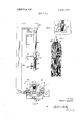
- FIG. 2 is a side elevation of a machine for assembling the mop head shown in FIG. 1;
- FIG. 3 is a fragmentary side elevation of the machine shown in FIG. 2 with the parts in mop head assembly positions, and
- FIG. 4 is a diagrammatic layout of the automatic control system according to the present invention.
- the present invention is concerned with an automatic control system for a machine such as that disclosed in US. Pat. No. 2,964,353 for assembling mop heads such as used for roofing mops and the like.
- a typical mop head is shown in FIG. 1 as comprising a bundle of strands 16 secured at the middle of the bundle by insertion of the intumed ends 20 of a U-shaped wire clamp 18 to a ferrule 22 having diametrically disposed nail holes 24 by which the mop head may be secured to a handle.
- the machine for assembling the mop head is shown in FIG. 2 and comprises a table having mounted thereon a vise l2 and a hydraulically operated cylinder assembly 14 which moves vertically to secure the mop head in assembly.
- the vise 12 comprises a pair of open ended chambers 26 fixedly secured to the table in alignment and separated by a space 30 which admits passage of the lower and ferrule carrying end of the cylinder assembly 14.
- a lever or jaw 32 Within each chamber 26 is moveably mounted a lever or jaw 32 which are operable to move toward and from each other by means of fluid cylinders 36 housing pistons 38 which are connected to the jaws 32 by rods 40.
- Feed lines 42,42 feed the hydraulic flluid both into and out of the cylinders 36.
- the ferrule holding cylinder assembly 14 is supported for vertical movement relative to the vise space 30 by a fixed piston 44 secured to a horizontal arm 46 extending forwardly from a standard 48 at the rear of the table.
- a vertical guide rod 50 is also fixed to and depends from the arm 46.
- the cylinder assembly 14 carries a rearwardly extending arm 52 having an opening 54 which slidably receives the guide arm 50. These parts cooperate to limit the movement of cylinder assembly 14 to a vertical path.
- the cylinder assembly 14 comprises a first, or upper, cylinder 56 and a second, or lower, cylinder 58 joined together in alignment by a coupling 60.
- a fluid line 62 is coupled to the upper closed end of cylinder 56, and a line 66 is connected to an opening in the coupling 60 and in communication with the lower end of cylinder 56.
- a fluid feed line 72 is 7 also connected to an opening in coupling 60 which communicates with the upper end of cylinder 58.
- a piston 73 rides within cylinder 58, and has at its lower end a reduced diameter extension 74 which strikes and bends the ends 20 of the mop loop 18 against the inner walls of ferrule 22 as shown in FIG. 3.
- the ferrule 22 to be assembled is clamped to the bottom of cylinder 58 and in axial alignment therewith by clamp arms 82 carrying detents 84 adapted to enter the ferrule openings 24, the arms 82 being operated by a lever 90.
- an operator positions a ferrule 22 against the lower edge of cylinder 58, anddrops a clamp loop 18 into the space 30 with its spread, intumed ends 20 held by the walls of chambers 26 and the edges of movable jaws 32.
- the operator places the mop material 16 on the table 10 with the central portions of the yarn disposed within the loop 18 whereupon the machine is :ready to operate.
- Fluid under pressure is then supplied sequentially (a) through inlet 66 into the lower end of cylinder 56 to lower the assembly 14 to insert the ferrule 22 between the spread ends of loop 18 and compress the mop material tightly within the loop, (b) through lines 42 to cylinders 36 which force the vise jaws 32 toward each other compressing the loop 18 and causing its sharpened ends 20 to pierce the ferrule wall, (c) through line 72 to cylinder 58 which forces piston 73 downwardly so that the extension 74 strikes the ends 20 of the loop and bends them against the inside wall of the ferrule as illustrated in FIG.
- FIG. 4 The circuit and components to effect the sequential operation described in general above, comprises, FIG. 4, a pressure fluid pump driven by any suitable means effecting continuous operation thereof.
- the pump has a fluid inlet 102 from a suitable reservoir R and a pressure fluid outlet 104 leading to a spool valve assembly 106 which normally allows the pressure fluid to be recycled back to the reservoir R by a return line 108.
- a pair of solenoids 110 and 112 are provided selectively to urge the spool valve assembly to either one of its two operative positions.
- the high pressure line 104 is connected through the spool valve assembly to a pressure fluid conduit 114 while a .pressure fluid conduit 116 is connected to the return line 108 whereas under control by the solenoid 112, the fluid conduit 114 is connected to the return line 108 while the pressure fluid conduit 116 is connected to the high pressure line 104.
- the electrical circuit includes a manually operated starting switch 118 for actuating a relay 120 to close normally open switches 122 and 124 by energization of the relay winding from line voltage across supply conductors 126,128.
- the conductor 128 is also connected to one side of the two solenoids 110 and 112, to the normally open switch 124 of the relay 120, and to the winding of a relay 132 and through conductor 134 to the normally open contact of a pressure-responsive switch 136.
- the other line conductor 126 is connected through conductor 138 to the normally open switches 122 and 140 of the respective relays 120 and 132, and through the conductor 142 to the normally closed contacts of the pressure-responsive switch 136 which complete the circuit through conductor 144 and the winding of the relay 120 to the other side of relay switch 124.
- the conductor 138 is also connected through conductor 145 to one of the normally closed contacts of pressureresponsive switch 146, the other of which contacts is connected through conductor 148 to the normally open switch 130 of relay 132.
- the relay 120 is energized to close its switches 122 and 124, the switch 124 serving to retain the relay energized while the pressure-responsive switch 136 remains in the position shown, and the switch 122 sewing to complete the circuit through conduit 121 and solenoid 110.
- High pressure fluid is now connected through conduits 114 and 66 to the cylinder 56, forcing the ferrule 22 down to compress the mop material.
- a pressure-responsive valve 150 opens to actuate the cylinders 36,36 through conduit [52 and lines 42,42.
- a pressure-responsive valve 154 opens to connect the lines 156 and 72 to the pressure fluid and thus actuate the cylinder 58.
- the pressure-responsive switch 136 is actuated to break the holding circuit through the winding of the relay 120 and to complete the circuit through conductor 134 and the winding of the relay 132.
- This action deenergizes relay 120, opens switch 122 and deenergizes solenoid 110, and energization of relay 132 closes switch 140 to energize through conductor 111 the solenoid 112 so that the line 116 is now connected to the pressure fluid while the line 114 is connected to return.
- the line 116 is connected to the lines 42 so that the pistons 38 are now retracted, and when fully so, a pressure-responsive valve 160 opens next to connect lines 116,162 with lines 62 and 75 and thereby effect simultaneous retraction of the cylinder 56 and of the piston 73.
- a pressure-responsive switch 146 is actuated to break the holding circuit for the relay 132, allowing the spool valve assembly 106 to return to its normal position.
- the control system assures proper and uniform operation of the mop making machine.
- the valve 150 will not open to close the jaws of the vise until the ferrule has been seated with sufficient pressure to compress the mop material properly.
- the valve 154 will not open until the vise has assured proper penetration and seating of the loops ends, whereafter the piston 74 is projected to bend over the loop ends.
- the pressureresponsive switch 136 reverses the fluid pressure connection by deenergizing the relay and energizing the relay 132.
- the vise is opened, and when fully so, the valve opens to retract the cylinder 56 and piston 73,74.
- Return to initial position causes the switch 146 to open, thus breaking the holding circuit to relay 132 and readying the system for the next cycle.
- a mop making machine comprising, in combination,
- a first double acting cylinder means for inserting a ferrule between the ends of the wire loop and for pressing the ferrule against the mop material
- a second double acting cylinder means for moving the jaws of the vise toward each other to pierce the loop ends through said ferrule
- a third ouble acting cylinder means carried by said first double acting cylinder for bending the wire loop ends against the inner wall of said ferrule
- a pump having an inlet from said reservoir and having an outlet
- valve means connected to the outlet of said pump and having first and second conduits connected thereto, said first conduit being connected to said first double acting cylinder means to insert said ferrule as aforesaid, a first branch conduit leading from said first conduit to said second double acting cylinder means, a normally closed pressure-responsive valve connected in said first branch conduit to assure predetermined compression of the mop material by the ferrule before said vise is actuated, a second branch conduit leading from the first branch conduit to said third double acting cylinder means, a pressure-responsive valve connected in said second branch conduit to assure penetration of said ferrule by the loop ends before said loop ends are bent against the inner surface of said ferrule,
- said second conduit being connected to said second double acting cylinder means to open the jaws of the vise, a third branch conduit leading from said second conduit to said first and third double acting cylinder means, a pressureresponsive valve connected in said third branch conduit to return said first and third double acting cylinder means after said vise jaws are opened,
- valve means for actuating said valve means selectively to connect said first and second conduits to the outlet of said pump, a manual switch in said actuating means for initiating a cycle of said valve means, a relay controlled by said manual switch, a holding circuit responsive to said first relay, a pressure-responsive switch connected to said first branch conduit, a second relay controlled by said pressure-responsive switch, a holding circuit responsive to said second relay, and a pressure-responsive switch connected to said third branch conduit.
- valve means normally recirculates fluid back to said reservoir.
Landscapes
- Cleaning Implements For Floors, Carpets, Furniture, Walls, And The Like (AREA)
- Treatment Of Fiber Materials (AREA)
Abstract
The sequence of operations for making a mop head are automatically cycled by the use of pressure-responsive valves and switches in a hydraulically actuated circuit. The pressureresponsive switches and valves assure that the individual operations are uniform from cycle-to-cycle and accommodate for variations in size, etc. which may be encountered from one mop head to another, thus assuring uniformity in the products.
Description
United States Patent 72] Inventor Gerald G. Swenson [56] References Cited Atlanta, UNITED STATES PATIENTS 968 1 2.9 4.353 12/1960 Carpenter et al. 300/16 7 [45] Patented July 6, 971 3,474,947 10/1969 Readyhough 227/7 [73] Assignec American Associated Companies Primary ExaminerGranville V. Custer, J r
Atlanta, Ga.
[54] MOP HEAD MAKING MACHINE WITH AUTOMATIC CYCLING CONTROL 2 Claims, 4 Drawing Figs. Us. 01 300/16 A46d 9/00 [50] Field of Search 300/16;
Attorney-Imirie and Smiley ABSTRACT: The sequence of operations for making a mop head are automatically cycled by the use of pressure-responsive valves and switches in a hydraulically actuated circuit. The pressure-responsive switches and valves assure that the individual operations are uniform from cycle-to-cycle and accommodate for variations in size, etc. which may be encountered from one mop head to another, thus assuring uniformity in the products.
PATENTED JUL sum 3591,23?
' sumznrz IN VENTOR GERAILD 6. SWENSON BY WM A TTORNE Y3 MOP HEAD MAKING MACHINE WITH AUTOMATIC CYCLING CONTROL BACKGROUND OF THE INVENTION US. Pat. No. 2,964,353, Dec. 13, 1960, discloses a mop making machine including a piston-actuated ferrule carrier for pressing the ferrule against a bundle of mop head strands, a pair of vise jaws for piercing the ends of a metal mop loop through the ferrule when it is pressed on said strands, and a plunger operating within the ferrule to bend over the ends of the mop loop. The patent discloses both a fully manually and an automatic control. The manual control is effective to produce uniform mop heads dependent upon the skill of the operator, while the automatic control depends upon position control devices which must be adjusted accurately for proper operation and which do not, in any event, make allowance for variations in the size of the mop head strands. Thus, the automatic control is incapable of compressing the mop head strands uniformly from cycle-to-cycle unless all of the bunches of strands are identical.
BRIEF SUMMARY OF THE INVENTION The present invention relates to an automatic cycling control for a mop making machine of the general type disclosed in the aforementioned patent wherein the control system is responsive to actuating pressure whereby uniform products are mad in rapid fashion, thus eliminating the necessity for skilled operators to produce uniform and acceptable products. According to the present invention, double acting pistoncylinder arrangements are utilized for actuating the vise jaws, the ferrule positioner and mop strand compressor, and the wire loop crimper. A main control valve is disposed in one of two operable positions, one in which the power strokes of the double acting pistons are initiated, and the other in which the return strokes are initiated. This valve is controlled by a pair of relay switches, and combinations of pressure-sensitive valves and a pressure-sensitive switch are included in each main control valve circuit for sequentially actuating the power strokes and then sequentially actuating the return strokes and return the system to initial condition.
BRIEF DESCRIPTION OF THE DRAWINGS FIG. I is an elevational view of an assembled mop head;
FIG. 2 is a side elevation of a machine for assembling the mop head shown in FIG. 1;
FIG. 3 is a fragmentary side elevation of the machine shown in FIG. 2 with the parts in mop head assembly positions, and
FIG. 4 is a diagrammatic layout of the automatic control system according to the present invention.
DETAILED DESCRIPTION OF THE INVENTION The present invention is concerned with an automatic control system for a machine such as that disclosed in US. Pat. No. 2,964,353 for assembling mop heads such as used for roofing mops and the like. A typical mop head is shown in FIG. 1 as comprising a bundle of strands 16 secured at the middle of the bundle by insertion of the intumed ends 20 of a U-shaped wire clamp 18 to a ferrule 22 having diametrically disposed nail holes 24 by which the mop head may be secured to a handle.
The machine for assembling the mop head is shown in FIG. 2 and comprises a table having mounted thereon a vise l2 and a hydraulically operated cylinder assembly 14 which moves vertically to secure the mop head in assembly. The vise 12 comprises a pair of open ended chambers 26 fixedly secured to the table in alignment and separated by a space 30 which admits passage of the lower and ferrule carrying end of the cylinder assembly 14. Within each chamber 26 is moveably mounted a lever or jaw 32 which are operable to move toward and from each other by means of fluid cylinders 36 housing pistons 38 which are connected to the jaws 32 by rods 40.
The ferrule holding cylinder assembly 14 is supported for vertical movement relative to the vise space 30 by a fixed piston 44 secured to a horizontal arm 46 extending forwardly from a standard 48 at the rear of the table. A vertical guide rod 50 is also fixed to and depends from the arm 46. The cylinder assembly 14 carries a rearwardly extending arm 52 having an opening 54 which slidably receives the guide arm 50. These parts cooperate to limit the movement of cylinder assembly 14 to a vertical path.
The cylinder assembly 14 comprises a first, or upper, cylinder 56 and a second, or lower, cylinder 58 joined together in alignment by a coupling 60. A fluid line 62 is coupled to the upper closed end of cylinder 56, and a line 66 is connected to an opening in the coupling 60 and in communication with the lower end of cylinder 56. A fluid feed line 72 is 7 also connected to an opening in coupling 60 which communicates with the upper end of cylinder 58. A piston 73 rides within cylinder 58, and has at its lower end a reduced diameter extension 74 which strikes and bends the ends 20 of the mop loop 18 against the inner walls of ferrule 22 as shown in FIG. 3. The ferrule 22 to be assembled is clamped to the bottom of cylinder 58 and in axial alignment therewith by clamp arms 82 carrying detents 84 adapted to enter the ferrule openings 24, the arms 82 being operated by a lever 90.
In operation of the machine, an operator positions a ferrule 22 against the lower edge of cylinder 58, anddrops a clamp loop 18 into the space 30 with its spread, intumed ends 20 held by the walls of chambers 26 and the edges of movable jaws 32. Next the operator places the mop material 16 on the table 10 with the central portions of the yarn disposed within the loop 18 whereupon the machine is :ready to operate. Fluid under pressure is then supplied sequentially (a) through inlet 66 into the lower end of cylinder 56 to lower the assembly 14 to insert the ferrule 22 between the spread ends of loop 18 and compress the mop material tightly within the loop, (b) through lines 42 to cylinders 36 which force the vise jaws 32 toward each other compressing the loop 18 and causing its sharpened ends 20 to pierce the ferrule wall, (c) through line 72 to cylinder 58 which forces piston 73 downwardly so that the extension 74 strikes the ends 20 of the loop and bends them against the inside wall of the ferrule as illustrated in FIG. 3, (d) through lines 42' to the opposite ends of cylinders 36 to retract the jaws 32, and (e) through inlet 62 to the top of cylinder 56, raising the assembly 14 to its initial position and simultaneously through inlet 75 to cylinder 58 returning piston 73 to starting position. The operator then operates lever to release the clamping arm 82 and removes the assembled mop head.
The circuit and components to effect the sequential operation described in general above, comprises, FIG. 4, a pressure fluid pump driven by any suitable means effecting continuous operation thereof. The pump has a fluid inlet 102 from a suitable reservoir R and a pressure fluid outlet 104 leading to a spool valve assembly 106 which normally allows the pressure fluid to be recycled back to the reservoir R by a return line 108. A pair of solenoids 110 and 112 are provided selectively to urge the spool valve assembly to either one of its two operative positions.
Under control by the solenoid 110, the high pressure line 104 is connected through the spool valve assembly to a pressure fluid conduit 114 while a .pressure fluid conduit 116 is connected to the return line 108 whereas under control by the solenoid 112, the fluid conduit 114 is connected to the return line 108 while the pressure fluid conduit 116 is connected to the high pressure line 104.
The electrical circuit includes a manually operated starting switch 118 for actuating a relay 120 to close normally open switches 122 and 124 by energization of the relay winding from line voltage across supply conductors 126,128. The conductor 128 is also connected to one side of the two solenoids 110 and 112, to the normally open switch 124 of the relay 120, and to the winding of a relay 132 and through conductor 134 to the normally open contact of a pressure-responsive switch 136..
The other line conductor 126 is connected through conductor 138 to the normally open switches 122 and 140 of the respective relays 120 and 132, and through the conductor 142 to the normally closed contacts of the pressure-responsive switch 136 which complete the circuit through conductor 144 and the winding of the relay 120 to the other side of relay switch 124. The conductor 138 is also connected through conductor 145 to one of the normally closed contacts of pressureresponsive switch 146, the other of which contacts is connected through conductor 148 to the normally open switch 130 of relay 132.
Thus, when the manual switch 118 is momentarily closed, the relay 120 is energized to close its switches 122 and 124, the switch 124 serving to retain the relay energized while the pressure-responsive switch 136 remains in the position shown, and the switch 122 sewing to complete the circuit through conduit 121 and solenoid 110. High pressure fluid is now connected through conduits 114 and 66 to the cylinder 56, forcing the ferrule 22 down to compress the mop material. As soon as the material has reached a predetermined degree of compression, corresponding to some predetermined pressure in the line 114, a pressure-responsive valve 150 opens to actuate the cylinders 36,36 through conduit [52 and lines 42,42.
As soon as the pressure in line 152 rises to some predetermined value, a pressure-responsive valve 154 opens to connect the lines 156 and 72 to the pressure fluid and thus actuate the cylinder 58.- When the pressure in line 156 rises to that value indicative of the proper operation of the extension 74, the pressure-responsive switch 136 is actuated to break the holding circuit through the winding of the relay 120 and to complete the circuit through conductor 134 and the winding of the relay 132. This action deenergizes relay 120, opens switch 122 and deenergizes solenoid 110, and energization of relay 132 closes switch 140 to energize through conductor 111 the solenoid 112 so that the line 116 is now connected to the pressure fluid while the line 114 is connected to return. The line 116 is connected to the lines 42 so that the pistons 38 are now retracted, and when fully so, a pressure-responsive valve 160 opens next to connect lines 116,162 with lines 62 and 75 and thereby effect simultaneous retraction of the cylinder 56 and of the piston 73. When the cycle is thus completed, a pressure-responsive switch 146 is actuated to break the holding circuit for the relay 132, allowing the spool valve assembly 106 to return to its normal position.
From the above, it will be clear that the control system assures proper and uniform operation of the mop making machine. For example, the valve 150 will not open to close the jaws of the vise until the ferrule has been seated with sufficient pressure to compress the mop material properly. Likewise, the valve 154 will not open until the vise has assured proper penetration and seating of the loops ends, whereafter the piston 74 is projected to bend over the loop ends. Thereafter, upon attainment of the proper bending action, the pressureresponsive switch 136 reverses the fluid pressure connection by deenergizing the relay and energizing the relay 132. At this time, the vise is opened, and when fully so, the valve opens to retract the cylinder 56 and piston 73,74. Return to initial position causes the switch 146 to open, thus breaking the holding circuit to relay 132 and readying the system for the next cycle.
lclaim:
1. A mop making machine comprising, in combination,
a vise for holding a wire loop having inturned ends and in which the mop material is laid,
a first double acting cylinder means for inserting a ferrule between the ends of the wire loop and for pressing the ferrule against the mop material,
a second double acting cylinder means for moving the jaws of the vise toward each other to pierce the loop ends through said ferrule, a third ouble acting cylinder means carried by said first double acting cylinder for bending the wire loop ends against the inner wall of said ferrule,
a pressure fluid reservoir,
a pump having an inlet from said reservoir and having an outlet,
valve means connected to the outlet of said pump and having first and second conduits connected thereto, said first conduit being connected to said first double acting cylinder means to insert said ferrule as aforesaid, a first branch conduit leading from said first conduit to said second double acting cylinder means, a normally closed pressure-responsive valve connected in said first branch conduit to assure predetermined compression of the mop material by the ferrule before said vise is actuated, a second branch conduit leading from the first branch conduit to said third double acting cylinder means, a pressure-responsive valve connected in said second branch conduit to assure penetration of said ferrule by the loop ends before said loop ends are bent against the inner surface of said ferrule,
said second conduit being connected to said second double acting cylinder means to open the jaws of the vise, a third branch conduit leading from said second conduit to said first and third double acting cylinder means, a pressureresponsive valve connected in said third branch conduit to return said first and third double acting cylinder means after said vise jaws are opened,
means for actuating said valve means selectively to connect said first and second conduits to the outlet of said pump, a manual switch in said actuating means for initiating a cycle of said valve means, a relay controlled by said manual switch, a holding circuit responsive to said first relay, a pressure-responsive switch connected to said first branch conduit, a second relay controlled by said pressure-responsive switch, a holding circuit responsive to said second relay, and a pressure-responsive switch connected to said third branch conduit.
2. An automatic mop making machine as defined in claim 1.
wherein said valve means normally recirculates fluid back to said reservoir.
Claims (2)
1. A mop making machine comprising, in combination, a vise for holding a wire loop having inturned ends and in which the mop material is laid, a first double acting cylinder means for inserting a ferrule between the ends of the wire loop and for pressing the ferrule against the mop material, a second double acting cylinder means for moving the jaws of the vise toward each other to pierce the loop ends through said ferrule, a third double acting cylinder means carried by said first double acting cylinder for bending the wire loop ends against the inner wall of said ferrule, a pressure fluid reservoir, a pump having an inlet from said reservoir and having an outlet, valve means connected to the outlet of said pump and having first and second conduits connected thereto, said first conduit being connected to said first double acting cylinder means to insert said ferrule as aforesaid, a first branch conduit leading from said first conduit to said second double acting cylinder means, a normally closed pressure-responsive valve connected in said first branch conduit to assure predetermined compression of the mop material by the ferrule before said vise is actuated, a second branch conduit leading from the first branch conduit to said third double acting cylinder means, a pressure-responsive valve connected in said second branch conduit to assure penetration of said ferrule by the loop ends before said loop ends are bent against the inner surface of said ferrule, said second conduit being connected to said second double acting cylinder means to open the jaws of the vise, a third branch conduit leading from said second conduit to said first and third double acting cylinder means, a pressure-responsive valve connected in said third branch conduit to return said first and third double acting cylinder means after said vise jaws are opened, means for actuating said valve means selectively to connect said first and second conduits to the outlet of said pump, a manual switch in said actuating means for initiating a cycle of said valve means, a relay controlled by said manual switch, a holding circuit responsive to said first relay, a pressureresponsive switch connected to said first branch conduit, a second relay controlled by said pressure-responsive switch, a holding circuit responsive to said second relay, and a pressure-responsive switch connected to said third branch conduit.
2. An automatic mop making machine as defined in claim 1. wherein said valve means normally recirculates fluid back to said reservoir.
Applications Claiming Priority (1)
| Application Number | Priority Date | Filing Date | Title |
|---|---|---|---|
| US77764168A | 1968-11-21 | 1968-11-21 |
Publications (1)
| Publication Number | Publication Date |
|---|---|
| US3591237A true US3591237A (en) | 1971-07-06 |
Family
ID=25110823
Family Applications (1)
| Application Number | Title | Priority Date | Filing Date |
|---|---|---|---|
| US777641A Expired - Lifetime US3591237A (en) | 1968-11-21 | 1968-11-21 | Mop head making machine with automatic cycling control |
Country Status (1)
| Country | Link |
|---|---|
| US (1) | US3591237A (en) |
Cited By (1)
| Publication number | Priority date | Publication date | Assignee | Title |
|---|---|---|---|---|
| US4270804A (en) * | 1978-02-28 | 1981-06-02 | Nicolas Boulachanis | Puff duster and mop-making machine |
Citations (2)
| Publication number | Priority date | Publication date | Assignee | Title |
|---|---|---|---|---|
| US2964353A (en) * | 1959-10-23 | 1960-12-13 | American Associated Companies | Mop making machine |
| US3474947A (en) * | 1967-08-25 | 1969-10-28 | Textron Inc | Stapling device control circuit |
-
1968
- 1968-11-21 US US777641A patent/US3591237A/en not_active Expired - Lifetime
Patent Citations (2)
| Publication number | Priority date | Publication date | Assignee | Title |
|---|---|---|---|---|
| US2964353A (en) * | 1959-10-23 | 1960-12-13 | American Associated Companies | Mop making machine |
| US3474947A (en) * | 1967-08-25 | 1969-10-28 | Textron Inc | Stapling device control circuit |
Cited By (1)
| Publication number | Priority date | Publication date | Assignee | Title |
|---|---|---|---|---|
| US4270804A (en) * | 1978-02-28 | 1981-06-02 | Nicolas Boulachanis | Puff duster and mop-making machine |
Similar Documents
| Publication | Publication Date | Title |
|---|---|---|
| US4601093A (en) | Wire insulation stripping apparatus | |
| US3570100A (en) | Insulation stripping attachment for electrical connector crimping press and connector crimping press having insulation stripping means | |
| US4139937A (en) | Apparatus for applying a tubular insulating housing to an electrical connector secured to a wire | |
| US4838129A (en) | Wire insulation stripping apparatus | |
| US3867754A (en) | Stripper crimper machine | |
| US2592276A (en) | Article assembling apparatus | |
| US4367575A (en) | Device for simultaneous connection of a series of cables to corresponding contacts | |
| US3174323A (en) | Crimping tool | |
| DE2926689A1 (en) | TRANSFER UNIT FOR TRANSFERING ELECTRICAL CORES FROM A MEASURING, CUTTING AND STRIPING MACHINE TO A CABLE CLAMPING MACHINE | |
| GB829501A (en) | Machines and methods for making electrical leads | |
| US3967356A (en) | Insertion tool operable in accordance with a predetermined program to insert a plurality of conductors in insulation-piercing contacts disposed on opposite sides of an electrical connector | |
| US3588984A (en) | Stripping and crimping apparatus | |
| EP0001891B1 (en) | Apparatus for inserting wires into electrical terminals | |
| US3591237A (en) | Mop head making machine with automatic cycling control | |
| US3133288A (en) | Clip tool | |
| US3323558A (en) | Wire tying apparatus | |
| US3423815A (en) | Fluid-actuated crimping press | |
| US2145461A (en) | Ring forming mechanism | |
| US2489377A (en) | Machine for mounting seals on bale straps | |
| US4129941A (en) | Splice gun | |
| US4730384A (en) | Machine for fastening a connector to a cable end by crimping | |
| US2966816A (en) | Clip positioning and clenching apparatus | |
| DE2062759C3 (en) | Feeding and cutting device for a machine for the simultaneous hitting of several electrical connectors | |
| US2964353A (en) | Mop making machine | |
| US2730719A (en) | Steiner |