US3582008A - Bimetal crusher liner - Google Patents
Bimetal crusher liner Download PDFInfo
- Publication number
- US3582008A US3582008A US842818A US3582008DA US3582008A US 3582008 A US3582008 A US 3582008A US 842818 A US842818 A US 842818A US 3582008D A US3582008D A US 3582008DA US 3582008 A US3582008 A US 3582008A
- Authority
- US
- United States
- Prior art keywords
- backing
- surface members
- wear
- crusher
- crushing
- Prior art date
- Legal status (The legal status is an assumption and is not a legal conclusion. Google has not performed a legal analysis and makes no representation as to the accuracy of the status listed.)
- Expired - Lifetime
Links
Images

Classifications
-
- B—PERFORMING OPERATIONS; TRANSPORTING
- B02—CRUSHING, PULVERISING, OR DISINTEGRATING; PREPARATORY TREATMENT OF GRAIN FOR MILLING
- B02C—CRUSHING, PULVERISING, OR DISINTEGRATING IN GENERAL; MILLING GRAIN
- B02C2/00—Crushing or disintegrating by gyratory or cone crushers
- B02C2/005—Lining
Definitions
- a typical crusher of this type is one in which the cone or head is gyrated within or beneath a bowl.
- the particular structures shown in the present application are wearing parts for use in crushers in which a head is gyrated to cause the wearing part or mantle of the head to move toward or away from the wearing part or liner of a surrounding bowl.
- the two wearing parts define a crushing cavity into which material isdischarged from above to be reduced.
- the liner and the mantle take the crushing wear, and with some materials undergoing crushing this wear may be tremendous, for example, where taconite is being crushed. In any event, the liner and mantle wear away, and they may wear away very rapidly.
- a composite crushing or wear-taking member in which we are able to employ for the wearing surface parts metal of adequate hardness for maximum resistance, while providing, also, a backing or supporting or connecting structure of a different material, with the necessary tensile strength to stand up under the pounding, wear and stress inevitable in the operation ofa crusher.
- a wear-taking body or wearing part is cast from metals or alloys having originally, or by treatment, a high Brinnell hardness.
- such parts or bodies are arranged as sections or segments about the crushing cavity, as will appear below.
- FIG. 1 is a partial, vertical, axial section through a type of crusher having a normally fixed bowl and a head gyrated within and beneath it;
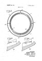
- FIG. 2 is a plan view on a different scale, illustrating a plurality of wear-taking segments such as are shown in the lower halfof FIG. 1;
- FIG. 3 is a partial axial section, on the same scale as FIG. 1, through a variant form of wear-taking segment and backing;
- FIG. 4 is a similar section through a variant form.
- 1 generally indicates a head which may be gyrated, the supporting and gyrating structure of the head forming themselves no part of the present invention.
- 2 indicates a bowl structure normally fixed in relation to the crusher as a whole. It may, for example, be mounted on a circumferential frame, or on a supporting ring mounted on a circumferential frame, the details of the frame and supporting connection being not of themselves part of the present invention.
- the bowl liner 3 indicates a bowl liner having mounted on its face a weartaking surface of harder material or metal, indicated at 4, and preferably formed in segments or separated parts.
- the backing portion 3 is preferably continuous throughout the circumference of the crusher, but applied to its lower surface are the plurality of wear-taking elements or segments 4.
- the surface or wear-taking segments or separate parts 4 are indicated as dovetailed into the lower surface of the liner 3, as at 45a. It Will be understood that any suitable means may be provided for uniting the segments 4 firmly to the backing 3, and the dovetailing is indicated primarily as a matter of illustration, since it provides a satisfactory method of joining the two parts. It will be understood, for example, that the backing part 3 may be preformed and the segments or wearing parts 4 poured to interpenetrate. 5 is any suitable means, such as a wedge, for securing the bowl liner 3 in its normal crushing position.
- a frustoconic ring or support 6 is shown which may extend entirely around the head, a part of which is indicated at l.
- the ring 6 may be of any suitable material which will resist cracking or breaking,'and which is not expected to receive crushing wear.
- the crushing wear is to be taken entirely by the subsequently described segments or surface members 7. Turning to these segments, they may, if desired, be subsequently poured to interpenetrate with the backing member or ring 6, as at the dovetails 70.
- each one of these continuous members of a metal which resists breakage, having formed on its wearing side a plurality of preferably separate bodies or segments of a harder metal adapted to resist crushing wear.
- a wide range of materials may be employed, including materials not necessarily metal, for example, ceramics.
- the material or metal selected for the protected parts 3 and 6 is chosen to resist breakage and to maintain its original form.
- the segments or wearing parts 4 and 7, on the other hand, are
- FIG. 2 we provide for the use of a multiple of segments 7, which, together, extend circumferentially about the lower part of the gyrated head I. These segments are independent, in the sense that they are separated and not a continuous ring.
- An interval 6a is shown between adjacent segments. This interval may be somewhat exaggerated in FIG. 2 to emphasize the fact that the segments are separate parts, are not connected to each other and, since they are separated are freed of the tendency to crack or break, which a closed ring of the same brittle metal would have.
- the mantle and the liner as a whole are tied together by the backing members 3 or 6, which are of less brittle material than the wearing faces or segments.
- a nonmetallic backing might be employed, such as an epoxy resin or a rubber carrier, with the metallic wear-taking parts or segments taking the entire wear.
- metallic backing layers as well as metallic wearing or surface segments.
- any suitable means may be employed for holding the mantle 6 in position. Illustrated, for example, is a pressure ring 9 of frustoconic form which may abut the portion 6d of the backing ring 6. Its upper end may be suitably secured to the gyrated shaft, not shown, of the head 1, in such fashion as to subject the abutment portion 6d to a downward and outward thrust, effective to hold the lower surface of the ring 6 against the outer surface of the head 1. As the head 1 is gyrated, for example, the mantle moves toward and away from the bowl liner 3 and the entire wear is taken by the wearing surfaces 4 and 7, respectively. if desired, any suitable backing material, metallic or nonmetallic, may be used between the outer surface of the head I and the opposed surface of the backing ring 6.
- the part in section may be initially poured of a suitable backing metal or material, for example, a backing of a metal which will resist breakage or fracture. This portion is indicated as at 20. Thereafter, the pouring may be finished by the application of a wearing layer 21 of substantially harder material than the backing material or metal 20. When it is poured it can be poured with dividers. Thus, if four radial dividers are employed the appearance of the ensuing structure may be as in FIG. 2.
- the backing portion 25, of a suitable metal or material will receive on its upper surface a wear-taking layer 26 which may be formed in sections generally as shown in FIG. 2, these sections to be bonded to the full lower ring 25.
- the shapes of the circumferential supports 3 and 6 may be widely varied, and may be formed to fit various types, shapes, or sizes of head, or of concave, or of both. Whereas the use of four segmental wear-taking members has been illustrated, this number may be increased or diminished.
- a full ring or support is combined with a plurality of wear-taking members or segments of a suitable metal or alloy, the individual segments or members being secured in relation to the backing ring, but being divided apart so that they are free from the tendency to crack or break.
- a bowl liner and a mantle are provided, each of which can be unitarily secured to the bowl or head with which they are employed, but each of which receives all wear upon special hard surfaces or members which are permanently secured to the circumferentially extending backing.
- wear-taking assemblies for use with a gyrated crusher head, and also with a normally fixed crushing bowl.
- wear-taking parts of hard material are exposed to wear, but are backed up by a circumferentially extending supporting or joining structure of softer material more resistant to breakage. It is important to have a plurality of hard or wear-taking parts or segments directed exposed to the material passing through and treated in the crushing cavity. These parts or segments perform the crushing or reducing function and receive all the wear or abrasion inevitable to such crushing.
- the separate parts or segments are of a hard material or special alloy, which do not form a closed ring or cone, but are backed up by the somewhat softer material, preferably of metal, which forms a circumferentially extending backing, as at 3 or 6. They are protected from wear and are of a material chosen to prevent cracking, breakage or rupture. So far as necessary, an additional backing of a soft metal may be employed, such as a zinc, or a plastic material, such, for example, as is sold under the trade name NORDBAK by the assignee hereof.
- pearlitic, carbidic white cast iron, or martensitic, carbidic, chrome-nickel alloyed cast iron, sometimes known as NIHARD may be used. Castings from such metal may be brittle and hard, but they have excellent wear characteristics.
- the material of which the backing parts or rings are formed is not critical. What is important is that a metal or material be employed which will not readily crack or rupture. Since it is the purpose of the invention to have the hard wearing portions take the crushing contacts, the backing structures do not have to have high wear-taking characteristics.
Landscapes
- Engineering & Computer Science (AREA)
- Mechanical Engineering (AREA)
- Food Science & Technology (AREA)
- Crushing And Grinding (AREA)
Abstract
Description
Claims (6)
Applications Claiming Priority (1)
| Application Number | Priority Date | Filing Date | Title |
|---|---|---|---|
| US84281869A | 1969-07-08 | 1969-07-08 |
Publications (1)
| Publication Number | Publication Date |
|---|---|
| US3582008A true US3582008A (en) | 1971-06-01 |
Family
ID=25288310
Family Applications (1)
| Application Number | Title | Priority Date | Filing Date |
|---|---|---|---|
| US842818A Expired - Lifetime US3582008A (en) | 1969-07-08 | 1969-07-08 | Bimetal crusher liner |
Country Status (1)
| Country | Link |
|---|---|
| US (1) | US3582008A (en) |
Cited By (13)
| Publication number | Priority date | Publication date | Assignee | Title |
|---|---|---|---|---|
| US3804345A (en) * | 1972-09-15 | 1974-04-16 | Barber Greene Co | Jaw crusher die mounting |
| US3834633A (en) * | 1972-04-13 | 1974-09-10 | Minneapolis Electric Steel Cas | Bowl and mantle assembly for cone crushers |
| US3845908A (en) * | 1971-10-22 | 1974-11-05 | Basf Ag | Conveyor machine for suspensions and viscous materials having a cage-like housing |
| US3923258A (en) * | 1974-05-22 | 1975-12-02 | Columbia Steel Casting | Upper liner securement for a gyratory crusher |
| US4571112A (en) * | 1981-05-14 | 1986-02-18 | Johnson Louis W | Joint assembly |
| US4773604A (en) * | 1982-09-23 | 1988-09-27 | Johnson Louis W | Seat member for gyratory rock crusher bowls |
| US5820045A (en) * | 1996-06-05 | 1998-10-13 | Nordberg Incorporated | Conical Crusher having a single piece outer crushing member |
| US20050156070A1 (en) * | 2002-05-23 | 2005-07-21 | Olsson Per A. | Wear part intended for a crusher and a method of manufacturing the same |
| US20120205473A1 (en) * | 2009-07-16 | 2012-08-16 | Martin Friz | Knife for a shredding machine, and use of such a knife in a shredding machine |
| CN103521289A (en) * | 2012-10-23 | 2014-01-22 | 洛阳天信矿山机械制造有限公司 | Cone crusher |
| US9399221B2 (en) | 2013-06-11 | 2016-07-26 | Metso Minerals Industries, Inc. | Vertical split bowl liner for cone crusher |
| CN110548560A (en) * | 2019-10-09 | 2019-12-10 | 攀钢集团矿业有限公司 | Movable cone lining plate and crusher |
| US20200391219A1 (en) * | 2017-12-22 | 2020-12-17 | Bradken Resources Pty Limited | Grinding mill liner |
-
1969
- 1969-07-08 US US842818A patent/US3582008A/en not_active Expired - Lifetime
Cited By (14)
| Publication number | Priority date | Publication date | Assignee | Title |
|---|---|---|---|---|
| US3845908A (en) * | 1971-10-22 | 1974-11-05 | Basf Ag | Conveyor machine for suspensions and viscous materials having a cage-like housing |
| US3834633A (en) * | 1972-04-13 | 1974-09-10 | Minneapolis Electric Steel Cas | Bowl and mantle assembly for cone crushers |
| US3804345A (en) * | 1972-09-15 | 1974-04-16 | Barber Greene Co | Jaw crusher die mounting |
| US3923258A (en) * | 1974-05-22 | 1975-12-02 | Columbia Steel Casting | Upper liner securement for a gyratory crusher |
| US4571112A (en) * | 1981-05-14 | 1986-02-18 | Johnson Louis W | Joint assembly |
| US4773604A (en) * | 1982-09-23 | 1988-09-27 | Johnson Louis W | Seat member for gyratory rock crusher bowls |
| US5820045A (en) * | 1996-06-05 | 1998-10-13 | Nordberg Incorporated | Conical Crusher having a single piece outer crushing member |
| US20050156070A1 (en) * | 2002-05-23 | 2005-07-21 | Olsson Per A. | Wear part intended for a crusher and a method of manufacturing the same |
| US20120205473A1 (en) * | 2009-07-16 | 2012-08-16 | Martin Friz | Knife for a shredding machine, and use of such a knife in a shredding machine |
| CN103521289A (en) * | 2012-10-23 | 2014-01-22 | 洛阳天信矿山机械制造有限公司 | Cone crusher |
| US9399221B2 (en) | 2013-06-11 | 2016-07-26 | Metso Minerals Industries, Inc. | Vertical split bowl liner for cone crusher |
| US20200391219A1 (en) * | 2017-12-22 | 2020-12-17 | Bradken Resources Pty Limited | Grinding mill liner |
| US11785893B2 (en) * | 2017-12-22 | 2023-10-17 | Bradken Resources Pty Limited | Grinding mill liner |
| CN110548560A (en) * | 2019-10-09 | 2019-12-10 | 攀钢集团矿业有限公司 | Movable cone lining plate and crusher |
Similar Documents
| Publication | Publication Date | Title |
|---|---|---|
| US3582008A (en) | Bimetal crusher liner | |
| CA2546556C (en) | Grinding roller for the pressure comminution of granular material | |
| EP1511572B1 (en) | A wear part intended for a crusher and a method of manufacturing the same | |
| US6523767B1 (en) | Grinding roller and method for the manufacture thereof | |
| US5516053A (en) | Welded metal hardfacing pattern for cone crusher surfaces | |
| US3834633A (en) | Bowl and mantle assembly for cone crushers | |
| JP2799250B2 (en) | Method for producing bimetal casting and wear parts produced by this method | |
| US4270705A (en) | Shell liner assembly for ore grinding mills | |
| US5080294A (en) | Gyratory mantle liner assembly | |
| US3682227A (en) | Method of making bi-metal crusher liner | |
| JPH0239939B2 (en) | ||
| CA2866949C (en) | Press roller for a roller press | |
| RU2413576C2 (en) | Mill composite lifting element | |
| US3587987A (en) | Segmented crusher liner | |
| US3473746A (en) | Wearing parts for crushers | |
| US3503564A (en) | Bowl for crushers and the like | |
| CN121103463A (en) | Crusher with wear elements and method for manufacturing crusher wear elements | |
| US20240382972A1 (en) | Mantle for a gyratory or cone crusher | |
| AU2014257641B2 (en) | Device for comminuting abrasive materials | |
| US6203588B1 (en) | Method of producing a grinding roll | |
| US5184389A (en) | Gyratory mantle liner assembly | |
| US883619A (en) | Crusher plate, head, and the like. | |
| WO2015015507A1 (en) | A grinding roller for vertical roller mill and method of manufacturing the same | |
| US3612421A (en) | Wearing parts for crushers | |
| US3536268A (en) | Mantle for cone crushers |
Legal Events
| Date | Code | Title | Description |
|---|---|---|---|
| AS | Assignment |
Owner name: REXNORD INC. Free format text: CHANGE OF NAME;ASSIGNOR:REX CHAIN BELT INC.;REEL/FRAME:004713/0513 Effective date: 19850905 |
|
| AS | Assignment |
Owner name: NORDBERG INC., A CORP. OF DE,WISCONSIN Free format text: ASSIGNMENT OF ASSIGNORS INTEREST;ASSIGNOR:REXNORD INC.;REEL/FRAME:004834/0102 Effective date: 19880126 Owner name: NORDBERG INC., 3073 S. CHASE AVE., MILWAUKEE, WI 5 Free format text: ASSIGNMENT OF ASSIGNORS INTEREST.;ASSIGNOR:REXNORD INC.;REEL/FRAME:004834/0102 Effective date: 19880126 |