US3551908A - Flame detector - Google Patents
Flame detector Download PDFInfo
- Publication number
- US3551908A US3551908A US693308A US3551908DA US3551908A US 3551908 A US3551908 A US 3551908A US 693308 A US693308 A US 693308A US 3551908D A US3551908D A US 3551908DA US 3551908 A US3551908 A US 3551908A
- Authority
- US
- United States
- Prior art keywords
- flame
- signal
- electrode
- electrodes
- modulated
- Prior art date
- Legal status (The legal status is an assumption and is not a legal conclusion. Google has not performed a legal analysis and makes no representation as to the accuracy of the status listed.)
- Expired - Lifetime
Links
- 239000007789 gas Substances 0.000 description 18
- 230000000694 effects Effects 0.000 description 11
- 235000014676 Phragmites communis Nutrition 0.000 description 9
- 238000002485 combustion reaction Methods 0.000 description 6
- 239000012212 insulator Substances 0.000 description 6
- 238000001514 detection method Methods 0.000 description 5
- 239000000446 fuel Substances 0.000 description 5
- 230000015556 catabolic process Effects 0.000 description 4
- 150000002500 ions Chemical class 0.000 description 4
- 239000000654 additive Substances 0.000 description 3
- 230000000996 additive effect Effects 0.000 description 3
- 230000009849 deactivation Effects 0.000 description 3
- 230000007613 environmental effect Effects 0.000 description 3
- 238000010438 heat treatment Methods 0.000 description 3
- 238000002955 isolation Methods 0.000 description 3
- 239000002184 metal Substances 0.000 description 3
- 230000004044 response Effects 0.000 description 3
- 239000000523 sample Substances 0.000 description 3
- 230000000007 visual effect Effects 0.000 description 3
- 230000008901 benefit Effects 0.000 description 2
- 238000005260 corrosion Methods 0.000 description 2
- 230000007797 corrosion Effects 0.000 description 2
- 239000003574 free electron Substances 0.000 description 2
- 230000003071 parasitic effect Effects 0.000 description 2
- OKTJSMMVPCPJKN-UHFFFAOYSA-N Carbon Chemical compound [C] OKTJSMMVPCPJKN-UHFFFAOYSA-N 0.000 description 1
- 238000009825 accumulation Methods 0.000 description 1
- 230000009471 action Effects 0.000 description 1
- 230000005540 biological transmission Effects 0.000 description 1
- 229910052799 carbon Inorganic materials 0.000 description 1
- 239000000919 ceramic Substances 0.000 description 1
- 230000008859 change Effects 0.000 description 1
- 239000004020 conductor Substances 0.000 description 1
- 239000000356 contaminant Substances 0.000 description 1
- 238000001816 cooling Methods 0.000 description 1
- 230000008021 deposition Effects 0.000 description 1
- 230000001627 detrimental effect Effects 0.000 description 1
- 238000010586 diagram Methods 0.000 description 1
- 238000010891 electric arc Methods 0.000 description 1
- 230000005672 electromagnetic field Effects 0.000 description 1
- 238000004880 explosion Methods 0.000 description 1
- 239000011521 glass Substances 0.000 description 1
- 231100001261 hazardous Toxicity 0.000 description 1
- 239000000463 material Substances 0.000 description 1
- 239000007787 solid Substances 0.000 description 1
- 239000004071 soot Substances 0.000 description 1
- 230000002459 sustained effect Effects 0.000 description 1
Images

Classifications
-
- F—MECHANICAL ENGINEERING; LIGHTING; HEATING; WEAPONS; BLASTING
- F23—COMBUSTION APPARATUS; COMBUSTION PROCESSES
- F23N—REGULATING OR CONTROLLING COMBUSTION
- F23N5/00—Systems for controlling combustion
- F23N5/02—Systems for controlling combustion using devices responsive to thermal changes or to thermal expansion of a medium
- F23N5/12—Systems for controlling combustion using devices responsive to thermal changes or to thermal expansion of a medium using ionisation-sensitive elements, i.e. flame rods
- F23N5/126—Systems for controlling combustion using devices responsive to thermal changes or to thermal expansion of a medium using ionisation-sensitive elements, i.e. flame rods using electrical or electromechanical means
-
- F—MECHANICAL ENGINEERING; LIGHTING; HEATING; WEAPONS; BLASTING
- F23—COMBUSTION APPARATUS; COMBUSTION PROCESSES
- F23N—REGULATING OR CONTROLLING COMBUSTION
- F23N5/00—Systems for controlling combustion
- F23N5/02—Systems for controlling combustion using devices responsive to thermal changes or to thermal expansion of a medium
- F23N5/12—Systems for controlling combustion using devices responsive to thermal changes or to thermal expansion of a medium using ionisation-sensitive elements, i.e. flame rods
- F23N5/123—Systems for controlling combustion using devices responsive to thermal changes or to thermal expansion of a medium using ionisation-sensitive elements, i.e. flame rods using electronic means
Definitions
- a flame detecting apparatus utilizing the ionization pattern of a flame gas to modulate a low voltage carrier signal impressed between a sender electrode and a receiver electrode.
- the result modulated signal at the receiver electrode is used to gate a gated latching switch, such as an SCR, which actuates an output switch to a readout device to indicate flame presence, both qualitatively and quantitatively.
- the voltage of the carrier signal is below the gating thershold of the latching switch so that upon flame cessation, the latching switch will not gate, thus deactivating the output switch.
- flame failure may be indicated by any suitable alarm.
- This invention deals with flame detectors and more particularly with the flame detectors utilizing the ionization pattern of flame gases to modulate a low voltage carrier signal impressed across the flame.
- flame combustion of fuels is used as a source of heat. It is essential in all such applications, in the interests of safety, that there be at no time an accumulation of unburner gases (such as will occur on flame flailure) which may become ignited due to spurious causes and cause an explosion. Therefore, it is necassary to have some means for giving an indication of flame failure, and preferably having this indication turn off the fuel to the combustion chamber.
- detectors There are available today many types of detectors to indicate flame failure and prevent the buildup of this potentially hazardous condition. These flame detectors are usually based on the following scientific principles:
- the equipment necessary to carry out such a principle is of a mechanically complicated nature and subject to moisture and corrosion failures. Furthermore, with each of the above principles, the detecting equipment is located within the flame environment and subject to the extreme conditions found there.
- the fourth principle on which flame detectors have been based involves making use of the electrical properties inherent in flame gases.
- the known electrical properties presently used are the (l) thermionic effect, (2) thermopile effect, and (3) are discharge effect.
- the thermionic effect involves the heating of two electrodes by a flame. If a potential gradient exists between the electrodes, heating lowers the work function of one electrode, and there will be emission of electrons therefrom. These electrons travel to the other electrode creating current flow between the two. This current flow is used to operate any suitable device to indicate flame. This effect is heat sensitive and will continue to indicate flame when in fact flame has ceased to exist if the electrodes are sufficiently hot.
- thermopile effect consists of heating an electrode causing a random drift current which results in a fluctuating polarized potential between the ends of the electrode. This drift is applied to the grid of a tube causing the tube to fire and send a signal to a device for indicating flame. Since only microamperes of current flow, a very high impedance device prone to noise is required.
- the are discharge effect involves applying a high potential between two electrodes which results in an arc discharge breakdown in the presence of the ionized flame gas between the electrodes. Upon breakdown a large current flows between the electrodes.
- This effect like the thermionic effect, is heat sensitive in that if the eloctordes are sufliciently heated, the gap breakdown will be sustained even though the flame is removed.
- This effect is also sensitive to electrode spacing; that is, the electrodes must be placed very close to one another in order for gap breakdown to occur. The close spacing will cause this arrangementto be sensitive to moisture and contaminant fouling.
- Atlhough subject to each of the above noted problems due to the environmental conditions existing in the area where flame is to be detected, there is a distinct advantage in using a means incorporating the electrical properties of the flame gases.
- the equipment used to indicate the existence or nonexistence of the flame may be remotely located from the flame source and is not subject to the intense heat and corrosion within the flame chamber.
- the only portion of the devices based on the electrical property principles which is subject to the flame environment are simple metal electrodes used as conductors in the flame.
- a flame is a highly ionized gaseous plasma composed of equal numbers of positive ions and free electrons with a minimum number of negative ions existing therein. The free electrons cause the flame gas to be electrically conductive.
- a slowly alternaterating electromagnetic field is impressed across the plasma, the field is modulated by the flame gas ionization pattern.
- This signal at the second electrode will have a modulated wave form (carrier signal p us a modulated additive).
- carrier signal p us a modulated additive.
- a signal translator responsive only to a signal of the magnitude of the modulated signal, directing the modulated signal received at the second electrode to an output device, there may be derived an indication of the existence of flame.
- the frequency of the modulated flame signal will vary as the flame pattern, thus giving a qualitative description of the fiame.
- a quantitative representation of flame intensity is also available since the amplitude of the modulated flame signal varies directly with flame intensity.
- the output device may be used in conjunction with a readout device to give a continuous visual indication of flame condition and intensity and, furthermore, may have adapted thereto a suitable alarm means operative to give an alarm upon cessation of the flame.
- the alarm means may be either visual or audible or may directly serve to cut off fuel flow to the burning device.
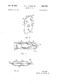
- FIG. 1 is a diagrammatic view of the flame detecting electrodes with the signals upon each shown respectively thereabove;
- FIG. 2 is a diagrammatic view of the electrodes, depicting the ionization of the gases therebetween;
- FIG. 3 is a diagrammatic view of the fundamental components of the flame detector of this invention.
- FIG. 4 is a schematic diagram showing the circuitry of the flame detector of this invention.
- FIG. 5 is a perspective view of the eddy plate with the flame detecting electrodes mounted thereon;
- FIG. 6 is a view, partly in section, of the reed relay ouput switch used in the detector circuit.
- FIG. 7 is a view, partly in section, of a modified form of the electrode used in this invention.
- FIG. 1 is illustrative of the flame gas characteristic upon which my invention is based.
- a carrier signal C of slowly alternating, low voltage wave form 10 is imposed through lead 12 on electrode 14.
- the signal, conducted through and modulated by flame 16, is impressed upon electrode 18.
- the modulated signal M received at electrode 18 consists of the carrier signal wave form 10 and modulated voltage peaks 20. This signal is taken from electrode 18 by lead 22.
- the flame gas existing between electrodes 14 and 18 consists of positive ions 24, electrons 26 and a few negative ions 28.
- carrier signal C When carrier signal C is applied to electrode 14, the gas electrons are modulated by the flame gas ionization pattern and travel to electrode 18 on carrier signal C.
- the electrons travel varying distances (for example, d :1 to give an additional potential level (modelation) to the imposed carrier C.
- Peaks 20, represent the sum of the carrier wave form 10 and the modulation additive as caused by this distance of travel of the electrons 26.
- FIG. 3 shows in diagrammatic form how I apply the flame gas ionization pattern signal modulation principle to flame detection.
- An alternating source '30 generates a signal between the ground 32 and electrode 14 through lead 12. The signal is transmitted to electrode 18 and passed through lead 22 to a signal translator 34. If a flame exists, the signal translator 34 will actuate an output device 36. When the flame ceases to exist, output device 36 will no longer be actuated and a suitable alarm means 38 may be activated.
- FIG. 4 shows one practical flame detecting application based on the principles of my invention as discussed above.
- An alternating voltage source e.g., line voltage
- the transformer 40 is fused, as at 42, for fail-safe operation.
- the low voltage alternating signal is passed through the isolation transformer 40 to the electrode 14 through lead 12 which is also fused for fail-safe operation as shown at 44.
- the circuit contains a suppressor 46 to prevent the transmission of line transients through the detecting circuit.
- Electrode 14 is mounted on an eddy plate 48 and insulated therefrom by insulator 50, as best seen in FIG. 5.
- Electrode 18 mounteded on the eddy plate 48 in spaced relationship therefrom is electrode 18 insulated from the eddy plate by insulator 54.
- the eddy plate 48 is positioned in a standard oil and gas ignitor horn 52 (best seen in FIG. 4) and serves the purpose of positioning the fuel nozzle 70 and spark plug 72.
- the electrodes are positioned so that they will be enveloped by the flame when a flame exists in the horn 52. While two electrodes are shown, other configurations may be adopted, such as using one electrode and arranging the horn 52 to serve as the other electrode.
- carrier signal C When carrier signal C is applied to electrode 14, this electrode acts as a sending probe sending a signal to electrode 18, which serves as a receiving probe.
- the signal received at electrode 18 is carried by line 22 to a signal translating device including an SCR 56 through a SCR gate current limiter 58 and an SCR voltage limiter 60. While this particular circuit specifies an SCR, any suitable gated latching switch may be used.
- the gating threshold of the SCR 56 is above the voltage of the alternating carrier signal C from the alternating source 30 impressed on receiving electrode 18-. It will, however, be gated by a voltage of a magnitude of the modulated signal M (carrier wave form 10 plus modulation additive) imposed on electrode 18 when a flame exists in horn 52.
- an output switch such as reed relay 62 will be activated to send a signal to readout device 64.
- This signal is directly related to flame pattern and intensity.
- the frequency of the modulated flame signal will vary as the flame pattern, while the amplitude of the modulated flame signal varies directly with the flame intensity. Therefore, upon presence of a flame, the readout device will enable one to determine not only existence thereof, but also the flame characteristics (qualitatively and quantitatively).
- Suitable alarm means 38 may be connected with reed relay 62 in such a manner so as to be responsive to deactivation of reed realy 62. Upon deactivation, the alarm 38 may send out a visual or audible signal and/or may serve to interrupt fuel supply to the ignitor horn 52 in any well known manner.
- a relay hold 68 which will store energy during this conductive portion and discharge the stored energy durlng the negative portion of the conduction cycle.
- the reed relay 62 is continuously activated until the time when SCR 56 ceases to be gated (i.e., no flame exists to modulate carrier signal C) at which time it is deactivated and triggers alarm 38.
- FIG. 6 shows a typical reed relay 62, such as that shown schematically in FIG. 4.
- An evacuated glass housing 74 surrounds support terminals 76, 78 of contacts 80, 82.
- contacts 80 and 82 will be brought together to close the circuit of the readout device 64 and alarm 38.
- the reed relay is only one form of output device actuating switch which may be used.
- the electrodes 14, 18 may be metal probes, I have found that standard aviation spark plugs will more efliciently serve as electrodes overcoming the problem of parasitic equivalent resistance build-up between the electrodes.
- Parasitic equivalent resistance build-up refers to carbon combustion products which collect between the electrodes providing a direct current path to short out the electrodes.
- the standard aviation spark plug consists of a housing 86 having an opening 88 therein. Within the housing is located a ceramic insulator 90 having an electrode tip 92 extending therefrom. A portion of the air 94 flowing in the horn 52 to support combustion will pass through opening 88 and blow out around extending electrode tip 92. This air circulation serves to remove any solid combustion products which would otherwise tend to build up on the electrode tip '92 keeping the tip clean,
- An apparatus for detecting flame condition comprising: a sender means and a receiver means, a low voltage alternating carrier signal imposed on said sender means and transmitted to said receiver means, said carrier signal being modulated when passed through a flame, a signal translator associated with said receiver means to receive said signal transmitted to said receiver mean, an output means to indicate flame condition, said output means actuated by said signal translator to indicate flame condition when said translator receives said modulated signal and actuated by said signal translator to indicate no flame when said translator no longer receives said modulated signal.
- said output means includes an output switch, a readout means and an alarm means, said signal translator closing said output switch to activate said readout means when said modulated signal is present and opening said output switch to activate said alarm means when said modulated signal is no longer received.
- said signal translator includes a gated latching switch, said latching switch allowing said output switch to be closed upon the passage of current through said latching switch, said current passing through said latching switch only when a voltage of the magnitude generated by said modulated carrier signal is received at the gate of said latching switch.
- said sender and receiver electrodes are spark plugs, each of said spark plugs having a housing, an insulator within the housing and an extended conductive tip extending from said insulator, said housing having means provided therein for passing air between said housing and said insulator and extended tip to prevent build-up of combustion products between said tip and said housing.
- said signal translator includes a gated latching switch, said latching switch allowing current to flow therethrough only upon reception at the gate thereof of a voltage of the magnitude generated by said modulated carrier signal.
Landscapes
- Engineering & Computer Science (AREA)
- Chemical & Material Sciences (AREA)
- Combustion & Propulsion (AREA)
- Mechanical Engineering (AREA)
- General Engineering & Computer Science (AREA)
- Other Investigation Or Analysis Of Materials By Electrical Means (AREA)
- Control Of Combustion (AREA)
Description
29, 1970 I w w. LANDON, JR ,5 1
FLAME DETECTOR Filed Dec. 26, 1967 2 Sheets-Sheet 1 INVENTOR WILLIAM W. LANDON JR.
Dec. 29, 1970 I w w ,1a 1; JR 3,551,908
FLAME DETECTOR 7 File 2d Dec. 2 1967 Q'Sheets-Sheet z FIG I H6 2 SIGNAL OUTPUT R TRANSLATOR DEVICE ALA M FIG. 3
INVENTOR WILLIAM W. LANDON JR.
United States 6 Claims ABSTRACT OF THE DISCLOSURE A flame detecting apparatus utilizing the ionization pattern of a flame gas to modulate a low voltage carrier signal impressed between a sender electrode and a receiver electrode. The result modulated signal at the receiver electrode is used to gate a gated latching switch, such as an SCR, which actuates an output switch to a readout device to indicate flame presence, both qualitatively and quantitatively. The voltage of the carrier signal is below the gating thershold of the latching switch so that upon flame cessation, the latching switch will not gate, thus deactivating the output switch. Upon output switch deactivation, flame failure may be indicated by any suitable alarm.
BACKGROUND AND SUMMARY OF THE INVENTION This invention deals with flame detectors and more particularly with the flame detectors utilizing the ionization pattern of flame gases to modulate a low voltage carrier signal impressed across the flame.
In many applications, including home and industry, flame combustion of fuels is used as a source of heat. It is essential in all such applications, in the interests of safety, that there be at no time an accumulation of unburner gases (such as will occur on flame flailure) which may become ignited due to spurious causes and cause an explosion. Therefore, it is necassary to have some means for giving an indication of flame failure, and preferably having this indication turn off the fuel to the combustion chamber. There are available today many types of detectors to indicate flame failure and prevent the buildup of this potentially hazardous condition. These flame detectors are usually based on the following scientific principles:
(1) thermostat affect;
(2) action of light sensitive thermionic tubes; (3) differential pressure within a flame; and (4) electrical properties of flame gases.
Each of the flame detectors based on the first three above-noted scientific princi les is subject to fundamental drawbacks. The thermostat as a slow response time because it is heat sensitive to the point where a finite period of time exists between flame cessation and the detection of environmental cooling to yield an indication of flame failure. The use of light sensitive thermionic tubes for detection has the objections that these systems require expensive and delicate ampifying means and are frequently rendered inoperative by deposition of soot. These devices also require accompanying fault detection equipment to insure they are properly operating.
When using the differential pressure principle for detection (measuring the change in pressure occurring between a point at which no flame exists and a point at which flame is intended to exist), the equipment necessary to carry out such a principle is of a mechanically complicated nature and subject to moisture and corrosion failures. Furthermore, with each of the above principles, the detecting equipment is located within the flame environment and subject to the extreme conditions found there.
"ice
The fourth principle on which flame detectors have been based involves making use of the electrical properties inherent in flame gases. The known electrical properties presently used are the (l) thermionic effect, (2) thermopile effect, and (3) are discharge effect.
The thermionic effect involves the heating of two electrodes by a flame. If a potential gradient exists between the electrodes, heating lowers the work function of one electrode, and there will be emission of electrons therefrom. These electrons travel to the other electrode creating current flow between the two. This current flow is used to operate any suitable device to indicate flame. This effect is heat sensitive and will continue to indicate flame when in fact flame has ceased to exist if the electrodes are sufficiently hot.
The thermopile effect consists of heating an electrode causing a random drift current which results in a fluctuating polarized potential between the ends of the electrode. This drift is applied to the grid of a tube causing the tube to fire and send a signal to a device for indicating flame. Since only microamperes of current flow, a very high impedance device prone to noise is required.
The are discharge effect involves applying a high potential between two electrodes which results in an arc discharge breakdown in the presence of the ionized flame gas between the electrodes. Upon breakdown a large current flows between the electrodes. This effect, like the thermionic effect, is heat sensitive in that if the eloctordes are sufliciently heated, the gap breakdown will be sustained even though the flame is removed. This effect is also sensitive to electrode spacing; that is, the electrodes must be placed very close to one another in order for gap breakdown to occur. The close spacing will cause this arrangementto be sensitive to moisture and contaminant fouling.
Atlhough subject to each of the above noted problems, due to the environmental conditions existing in the area where flame is to be detected, there is a distinct advantage in using a means incorporating the electrical properties of the flame gases. The equipment used to indicate the existence or nonexistence of the flame may be remotely located from the flame source and is not subject to the intense heat and corrosion within the flame chamber. The only portion of the devices based on the electrical property principles which is subject to the flame environment are simple metal electrodes used as conductors in the flame.
I have discovered a fourth electrical characteristic of flame gases which may be used in flame detecting incorpo rating the advantages, while not subject to the negative limitations, of the above electrical property effects. A flame is a highly ionized gaseous plasma composed of equal numbers of positive ions and free electrons with a minimum number of negative ions existing therein. The free electrons cause the flame gas to be electrically conductive. When a slowly altenrating electromagnetic field is impressed across the plasma, the field is modulated by the flame gas ionization pattern. By placing two electrodes in the area in which a flame is to exist and impressing a slowly alternating low voltage signal on one of the electrodes, in the presence of flame a signal will be received at the other electrode. This signal at the second electrode will have a modulated wave form (carrier signal p us a modulated additive). By means of a signal translator responsive only to a signal of the magnitude of the modulated signal, directing the modulated signal received at the second electrode to an output device, there may be derived an indication of the existence of flame. The frequency of the modulated flame signal will vary as the flame pattern, thus giving a qualitative description of the fiame. A quantitative representation of flame intensity is also available since the amplitude of the modulated flame signal varies directly with flame intensity. The output device may be used in conjunction with a readout device to give a continuous visual indication of flame condition and intensity and, furthermore, may have adapted thereto a suitable alarm means operative to give an alarm upon cessation of the flame. The alarm means may be either visual or audible or may directly serve to cut off fuel flow to the burning device.
BRIEF DESCRIPTION OF THE DRAWINGS FIG. 1 is a diagrammatic view of the flame detecting electrodes with the signals upon each shown respectively thereabove;
FIG. 2 is a diagrammatic view of the electrodes, depicting the ionization of the gases therebetween;
FIG. 3 is a diagrammatic view of the fundamental components of the flame detector of this invention;
FIG. 4 is a schematic diagram showing the circuitry of the flame detector of this invention;
FIG. 5 is a perspective view of the eddy plate with the flame detecting electrodes mounted thereon;
FIG. 6 is a view, partly in section, of the reed relay ouput switch used in the detector circuit; and
FIG. 7 is a view, partly in section, of a modified form of the electrode used in this invention.
DESCRIPTION OF THE PREFERRED EMBODIMENT Referring now to the drawings, FIG. 1 is illustrative of the flame gas characteristic upon which my invention is based. A carrier signal C of slowly alternating, low voltage wave form 10 is imposed through lead 12 on electrode 14. The signal, conducted through and modulated by flame 16, is impressed upon electrode 18. The modulated signal M received at electrode 18 consists of the carrier signal wave form 10 and modulated voltage peaks 20. This signal is taken from electrode 18 by lead 22.
As illustrated in FIG. 2, the flame gas existing between electrodes 14 and 18 consists of positive ions 24, electrons 26 and a few negative ions 28. When carrier signal C is applied to electrode 14, the gas electrons are modulated by the flame gas ionization pattern and travel to electrode 18 on carrier signal C. The electrons travel varying distances (for example, d :1 to give an additional potential level (modelation) to the imposed carrier C. Peaks 20, represent the sum of the carrier wave form 10 and the modulation additive as caused by this distance of travel of the electrons 26.
FIG. 3 shows in diagrammatic form how I apply the flame gas ionization pattern signal modulation principle to flame detection. An alternating source '30 generates a signal between the ground 32 and electrode 14 through lead 12. The signal is transmitted to electrode 18 and passed through lead 22 to a signal translator 34. If a flame exists, the signal translator 34 will actuate an output device 36. When the flame ceases to exist, output device 36 will no longer be actuated and a suitable alarm means 38 may be activated.
FIG. 4 shows one practical flame detecting application based on the principles of my invention as discussed above. An alternating voltage source (e.g., line voltage) applies a low voltage alternating signal to an isolation transformer 40. The purpose of the isolation transformer is merely to isolate the circuit from ground. The transformer 40 is fused, as at 42, for fail-safe operation. The low voltage alternating signal is passed through the isolation transformer 40 to the electrode 14 through lead 12 which is also fused for fail-safe operation as shown at 44. The circuit contains a suppressor 46 to prevent the transmission of line transients through the detecting circuit. Electrode 14 is mounted on an eddy plate 48 and insulated therefrom by insulator 50, as best seen in FIG. 5. Mounted on the eddy plate 48 in spaced relationship therefrom is electrode 18 insulated from the eddy plate by insulator 54. The eddy plate 48 is positioned in a standard oil and gas ignitor horn 52 (best seen in FIG. 4) and serves the purpose of positioning the fuel nozzle 70 and spark plug 72. The electrodes are positioned so that they will be enveloped by the flame when a flame exists in the horn 52. While two electrodes are shown, other configurations may be adopted, such as using one electrode and arranging the horn 52 to serve as the other electrode.
When carrier signal C is applied to electrode 14, this electrode acts as a sending probe sending a signal to electrode 18, which serves as a receiving probe. The signal received at electrode 18 is carried by line 22 to a signal translating device including an SCR 56 through a SCR gate current limiter 58 and an SCR voltage limiter 60. While this particular circuit specifies an SCR, any suitable gated latching switch may be used. The gating threshold of the SCR 56 is above the voltage of the alternating carrier signal C from the alternating source 30 impressed on receiving electrode 18-. It will, however, be gated by a voltage of a magnitude of the modulated signal M (carrier wave form 10 plus modulation additive) imposed on electrode 18 when a flame exists in horn 52.
When the SCR 56 is gated, an output switch such as reed relay 62 will be activated to send a signal to readout device 64. This signal is directly related to flame pattern and intensity. The frequency of the modulated flame signal will vary as the flame pattern, while the amplitude of the modulated flame signal varies directly with the flame intensity. Therefore, upon presence of a flame, the readout device will enable one to determine not only existence thereof, but also the flame characteristics (qualitatively and quantitatively).
Upon cessation of flame, SCR 56 will cease to be gated and reed relay 62 will be deactivated. Suitable alarm means 38 may be connected with reed relay 62 in such a manner so as to be responsive to deactivation of reed realy 62. Upon deactivation, the alarm 38 may send out a visual or audible signal and/or may serve to interrupt fuel supply to the ignitor horn 52 in any well known manner.
Since an SCR will conduct only during the positive half of a conduction cycle, I have included in this circuit a relay hold 68 which will store energy during this conductive portion and discharge the stored energy durlng the negative portion of the conduction cycle. In this manner, the reed relay 62 is continuously activated until the time when SCR 56 ceases to be gated (i.e., no flame exists to modulate carrier signal C) at which time it is deactivated and triggers alarm 38.
FIG. 6 shows a typical reed relay 62, such as that shown schematically in FIG. 4. An evacuated glass housing 74 surrounds support terminals 76, 78 of contacts 80, 82. When the coil of reed relay 62 (surrounding housing '74 but not shown) is activated by the gating of SCR 56, contacts 80 and 82 will be brought together to close the circuit of the readout device 64 and alarm 38. It is to be understood, of course, that the reed relay is only one form of output device actuating switch which may be used.
Although the electrodes 14, 18 may be metal probes, I have found that standard aviation spark plugs will more efliciently serve as electrodes overcoming the problem of parasitic equivalent resistance build-up between the electrodes. Parasitic equivalent resistance build-up refers to carbon combustion products which collect between the electrodes providing a direct current path to short out the electrodes. As shown in FIG. 7 the standard aviation spark plug consists of a housing 86 having an opening 88 therein. Within the housing is located a ceramic insulator 90 having an electrode tip 92 extending therefrom. A portion of the air 94 flowing in the horn 52 to support combustion will pass through opening 88 and blow out around extending electrode tip 92. This air circulation serves to remove any solid combustion products which would otherwise tend to build up on the electrode tip '92 keeping the tip clean,
In view of the above disclosure it can be seen that I have developed a flame detector not subject to the extreme environmental conditions or the above-enumerated detrimental electrocal characteristics which have plagued previous flame detectors. Utilizing the ionization pattern of the flame gas itself, -I have invented a low voltage detector which may be used through an appropriate readout device to transmit an accurate picture of flame pattern and intensity and which is instantly responsive to flame failure to trigger a suitable alarm means. The circuitry as shown in a typical application is simple and small in size. The flame detector of my invention gives a more reliable response in a smaller response time at less cost than any detector available today.
It will be understood that various changes in the details, materials, and arrangements of parts which have been herein described and illustrated in order to explain the nature of the invention, may be made by those skilled in the art within the principle and scope of the invention as expressed in the appended claims.
I claim:
1. An apparatus for detecting flame condition comprising: a sender means and a receiver means, a low voltage alternating carrier signal imposed on said sender means and transmitted to said receiver means, said carrier signal being modulated when passed through a flame, a signal translator associated with said receiver means to receive said signal transmitted to said receiver mean, an output means to indicate flame condition, said output means actuated by said signal translator to indicate flame condition when said translator receives said modulated signal and actuated by said signal translator to indicate no flame when said translator no longer receives said modulated signal.
2. The apparatus of claim 1 wherein said output means includes an output switch, a readout means and an alarm means, said signal translator closing said output switch to activate said readout means when said modulated signal is present and opening said output switch to activate said alarm means when said modulated signal is no longer received.
3. The apparatus of claim 2 wherein said signal translator includes a gated latching switch, said latching switch allowing said output switch to be closed upon the passage of current through said latching switch, said current passing through said latching switch only when a voltage of the magnitude generated by said modulated carrier signal is received at the gate of said latching switch.
4. The apparatus of claim 1 wherein said sender means and said receiver means are metal electrodes electrically insulated and spaced from one another, said electrodes located so as to be enveloped by said flame.
5. The apparatus of claim 4 wherein said sender and receiver electrodes are spark plugs, each of said spark plugs having a housing, an insulator within the housing and an extended conductive tip extending from said insulator, said housing having means provided therein for passing air between said housing and said insulator and extended tip to prevent build-up of combustion products between said tip and said housing.
2 6. The apparatus of claim 1 wherein said signal translator includes a gated latching switch, said latching switch allowing current to flow therethrough only upon reception at the gate thereof of a voltage of the magnitude generated by said modulated carrier signal.
References Cited UNITED STATES PATENTS 2,820,945 1/1958 Marsden 340- 228.2X
3,041,589 6/1962 Dietz 340228.2 3,348,104 10/1967 Zielinski et al. 340'228.1X
3,437,884 4/1969 Mandock et al. 340--228X FOREIGN PATENTS 1,111,909 4/1954 France 340-228.1
THOMAS B. HABECKER, Primary Examiner DAVID L. TRAFTON, Assistant Examiner U.S. Cl. X.R.
Applications Claiming Priority (1)
| Application Number | Priority Date | Filing Date | Title |
|---|---|---|---|
| US69330867A | 1967-12-26 | 1967-12-26 |
Publications (1)
| Publication Number | Publication Date |
|---|---|
| US3551908A true US3551908A (en) | 1970-12-29 |
Family
ID=24784142
Family Applications (1)
| Application Number | Title | Priority Date | Filing Date |
|---|---|---|---|
| US693308A Expired - Lifetime US3551908A (en) | 1967-12-26 | 1967-12-26 | Flame detector |
Country Status (6)
| Country | Link |
|---|---|
| US (1) | US3551908A (en) |
| DE (1) | DE1815968A1 (en) |
| ES (1) | ES361790A1 (en) |
| FR (1) | FR1598090A (en) |
| GB (1) | GB1217930A (en) |
| NL (1) | NL6818634A (en) |
Cited By (2)
| Publication number | Priority date | Publication date | Assignee | Title |
|---|---|---|---|---|
| USD245588S (en) * | 1976-03-02 | 1977-08-30 | Hoge Henri H | Ionization sensor for smoke detector |
| DE102008028423A1 (en) * | 2008-06-17 | 2009-12-24 | Viessmann Werke Gmbh & Co Kg | Method and device for determining at least one influencing variable of a combustion process |
Families Citing this family (2)
| Publication number | Priority date | Publication date | Assignee | Title |
|---|---|---|---|---|
| DE4433425C2 (en) * | 1994-09-20 | 1998-04-30 | Stiebel Eltron Gmbh & Co Kg | Control device for setting a gas-combustion air mixture in a gas burner |
| DE10125574A1 (en) | 2001-05-25 | 2002-11-28 | Siemens Building Tech Ag | Flame monitoring device |
-
1967
- 1967-12-26 US US693308A patent/US3551908A/en not_active Expired - Lifetime
-
1968
- 1968-12-20 DE DE19681815968 patent/DE1815968A1/en active Pending
- 1968-12-23 GB GB60948/68A patent/GB1217930A/en not_active Expired
- 1968-12-23 ES ES361790A patent/ES361790A1/en not_active Expired
- 1968-12-24 FR FR1598090D patent/FR1598090A/fr not_active Expired
- 1968-12-24 NL NL6818634A patent/NL6818634A/xx unknown
Cited By (3)
| Publication number | Priority date | Publication date | Assignee | Title |
|---|---|---|---|---|
| USD245588S (en) * | 1976-03-02 | 1977-08-30 | Hoge Henri H | Ionization sensor for smoke detector |
| DE102008028423A1 (en) * | 2008-06-17 | 2009-12-24 | Viessmann Werke Gmbh & Co Kg | Method and device for determining at least one influencing variable of a combustion process |
| DE102008028423B4 (en) * | 2008-06-17 | 2012-02-09 | Viessmann Werke Gmbh & Co Kg | Method and device for determining at least one influencing variable of a combustion process |
Also Published As
| Publication number | Publication date |
|---|---|
| GB1217930A (en) | 1971-01-06 |
| FR1598090A (en) | 1970-06-29 |
| ES361790A1 (en) | 1970-11-01 |
| NL6818634A (en) | 1969-06-30 |
| DE1815968A1 (en) | 1969-08-07 |
Similar Documents
| Publication | Publication Date | Title |
|---|---|---|
| US3185846A (en) | Ultra-violet radiation flame monitor | |
| US2304641A (en) | Control apparatus | |
| US2798213A (en) | Checking technique and system | |
| US2313943A (en) | Control apparatus | |
| US3147380A (en) | Nuclear bomb explosion detecting device | |
| US3551908A (en) | Flame detector | |
| US3460125A (en) | Method and apparatus for detecting gaseous impurities | |
| US3909815A (en) | Detector for fumes and combustion gases | |
| US2748846A (en) | Combustion safeguard apparatus | |
| US2374610A (en) | Control apparatus | |
| US2136256A (en) | Furnace control system | |
| US3445172A (en) | Fail-safe system | |
| US4107657A (en) | Flame detecting apparatus | |
| US2465377A (en) | Gas-sensing control means with gas-discharge device | |
| US2544930A (en) | Pilot burner and flame detector assembly | |
| US2541236A (en) | Electrode mounting device | |
| US2737643A (en) | Flame detection apparatus | |
| US4211746A (en) | Flame ionization detector | |
| US2610677A (en) | Fuel burner safety control apparatus | |
| US3473895A (en) | Flame ionisation detectors | |
| US2579884A (en) | Flame failure safeguard | |
| US2444239A (en) | High-frequency spark igniter means for burners | |
| US2749447A (en) | Fuel burner control apparatus | |
| US2460314A (en) | Apparatus for supervising heat generating means | |
| US3042907A (en) | Smoke detector |