US3550581A - Apparatus and method for determining the tendency to thrombose - Google Patents
Apparatus and method for determining the tendency to thrombose Download PDFInfo
- Publication number
- US3550581A US3550581A US586893A US3550581DA US3550581A US 3550581 A US3550581 A US 3550581A US 586893 A US586893 A US 586893A US 3550581D A US3550581D A US 3550581DA US 3550581 A US3550581 A US 3550581A
- Authority
- US
- United States
- Prior art keywords
- needle
- tube
- blood
- thrombose
- stylet
- Prior art date
- Legal status (The legal status is an assumption and is not a legal conclusion. Google has not performed a legal analysis and makes no representation as to the accuracy of the status listed.)
- Expired - Lifetime
Links
Images


Classifications
-
- G—PHYSICS
- G01—MEASURING; TESTING
- G01N—INVESTIGATING OR ANALYSING MATERIALS BY DETERMINING THEIR CHEMICAL OR PHYSICAL PROPERTIES
- G01N33/00—Investigating or analysing materials by specific methods not covered by groups G01N1/00 - G01N31/00
- G01N33/48—Biological material, e.g. blood, urine; Haemocytometers
- G01N33/483—Physical analysis of biological material
- G01N33/487—Physical analysis of biological material of liquid biological material
- G01N33/49—Blood
- G01N33/4905—Determining clotting time of blood
Definitions
- thrombose is determined APPARATUS AND METHOD FOR DETERMINING THE TENDENCY TO TI-IROMBOSE
- This invention relates to an apparatus for determining the tendency to thrombose andthe method for employing the apparatus. More particularly, the invention relates to the method and apparatus which provides for controlled flow of blood, free of catalytic agents from surrounding tissue which cause premature clot formation, whereby the tendency to throm' hose is determined by blood clot'formation in the apparatus.
- Another object of my invention is tolprovide a relatively inexpensive apparatus whose component parts are easily manufactured and easily assembled for ready use and which apparatus may be employed by persons with minimal technical skill to determine rather rapidly the tendency to thrombose.
- My invention generally contemplates providing a method and apparatus for determining the tendency to thrombose.
- I provide an apparatus comprising a surgical assembly including a tubular needle member with a smooth shank and a needle handle portionmounted adjacent one end thereof.
- a tight-fitting stylet member having a stylet handle portion at one end is removably mounted within the needle bore so that the stylet handle portion nests within the needle handle portion whereby the members are coaxially disposed.
- the other end of at least one of the members terminates in a sharp puncture end which is capable of puncturing a blood vessel.
- a flexible elongated tube is provided having means at one end for mounting the tube on the surgical assembly-with the tube being mounted adjacent the needle handleportion upon removal of the stylet was to form a continuous flow passage through the needle and tube.
- the tube is formed having an internal diameter at least as large as the internal diameter of the needle so that blood will initially flow.
- the above apparatus is employed by first puncturing a vein with the surgical assembly of the type having a neev dle fitted with a stylet. Since the tight-fitting stylet substantially fills the bore of the needle, the entrance of tissue thromboplastin into the bore of the-needle, resulting from the puncture, is substantially minimizedthereby obviating premature clot formation withintheapparatus. After the vein has been punctured, the stylet is removed allowing a small amount of blood to pass through the needle to flush any remaining tissue thromboplastin present in the blood.
- a flexible tube is mounted on the surgical assembly fonning a continuous passage through the needle and tube so that blood will flow therethrough in a continuous and substantially uniform flow.
- the flow of blood through the apparatus is maintained until a clot forms within the' flexible tube whereby the tendency to thrombose is determined.
- FIG. I is an elevational view of the component parts of the unassembled apparatus;'; p v
- FIG. 2 is a vertical sectional view of the surgical assembly
- FIG. 3 is a sectional view taken on the line 3-3 of FIG. 2;
- FIGS. 4 and 5 are fragmentary sectional views of two forms of the puncture end of the surgical assembly
- FIG. 6 is an elevational view, partly broken away, of the apparatus depicting blood flowing through the end of the flexible elongated tube into a container;
- FIG. 7 is a view similar to FIG. I of another embodiment of the apparatus.
- FIG. 9'
- FIG. 11 is a view in vertical section showing alternative structure for mounting the flexible tube on the apparatus of FIG. 1;
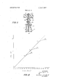
- FIG. 12 is a graph showing a typical plot of readings 'obtained through the use of the apparatus wherein blood volume in relation to time is recorded.
- FIGS- 1' 3 and 6 the apparatus is generally indicated by numeral 10.
- the apparatus comprises a surgical assembly 12 which includes a tubular needle member 14 formed with a smooth shank and provided with a needle handle portion 16 mounted adjacent end l8 of needle 14 by employing any suitable adhe sive material, such as an epoxy resin E.
- Needle handle I6 is formed having a bore 17 with its outer end surface provided with a slot 20 to form one portion of the lock means of the surgical assembly. Needle l4'is centered in handle portion 16 by bore 19 which communicates with bore 17 so that end portion 18 of needle I4extends beyond handle 16.
- Stylet handle 23 is formed having an upper flanged head 24 and a depending hollow skirt portion 26. Whenstylet 22 is positioned in stylet handle 23 it is coaxially spaced from the inner surfaces 25 of skirt 26 and is centered therein through opening 27. Stylet 22 and stylet handle 23 are mounted in fixed position by anysuitable adhesive, such as an epoxy resin E. Stylet 22 is removably mounted within needle 14 so that skirt: 26 of stylet handle 23 nests within needle handle portion I6 so that end portion 18 of needle 14 is telescopically positioned within skirt 26 of stylet handle 23 as shown most clearly in FIG. 2.-
- a tab 29 is formed and depending from the outer edge of flanged head 24 so that when the stylet 22 is disposed within the needle 14, the surgical assembly will be locked from axial rotation.
- FIGS. 4 and 5 representative puncturing ends are shown.
- the former figure depicts a beveled end while the latter figure depicts an end formed into a pencil tip or conical end portion.
- needle 42 provides a sharp beveled puncture point 49.
- a stylet, such as stylet' 22- or 50, of complementary end configuration is received within needle 42 so as to substantially close the needle bore opening thereby to form a smooth surface 48 (see FIG. 7).
- stylet 22 is formed to provide a sharp conical puncturing tip 28 and extends beyond the beveled end 30 of needle '14. Both end portions are machined by conventional grinding techniques so as to form a substantially smooth continuous surface.
- FIG. 1 provides a puncture end as shown in FIG. 5 it is apparent that the puncture end of FIG. 4 may be substituted in lieu thereof.
- the apparatus of FIG. 7 may employ the puncture end of FIG. 5.
- any suitable configuration may be employed as the puncture end in accordance herewith.
- Flexible tube 34 is formed having outwardly extending Also, end 32 of needle 14 is tapered such that a substantially continuous passage is formed when tube 34 is mounted over end 32 of needle 14.
- the apparatus is assembled depicting blood flowing from a vein V through needle 14 and flexible tube 34 so that blood is received in container 38.
- the container is provided with graduations G for determining the volume and rate of blood flow.
- Tube 34 is positioned within container 38 preferably by passing end 37 through central opening 39 of stopper 40 with tube 34 depending into container 38.
- An air vent 33 is provided to stopper 40 so as to remove excess air as blood is collected in container 38.
- Surgical assembly 41 as shown in FIG. 7 comprises a tubular needle member 42 mounted in needle handle portion 44 at end 45 thereof. Needle 42 is centered at end 45 in bore 46 of needle handle 44 and held in position by any suitable adhesive, such as an epoxy resin E. Bore 46 communicates with opening 47 formed in needle handle 44. Stylet 50 is mounted at one end in stylet handle 52 through bore 54 formed therein and is held in position by any suitable adhesive, such as an epoxy resin E. Stylet handle 52 is formed having a depending skirt 56 which is of size substantially equal to the diameter of opening 47 of needle handle 44. When stylet 50 is removably mounted within tubular needle 42, skirt 56 of stylet handle 52 will nest therein. To prevent axial rotation of the stylet within the surgical assembly 41 21 depending tab portion 57 is formed in stylet handle 52 and disposed in a complementary formed notch 58 on needle handle 44.
- Tube mounting means 60 is formed having a head portion 62 and integrally formed therewith is a depending plug portion 64 which is of a size substantially equal to the diameter of bore 47 of needle handle 44.
- Tube mounting means 60 is formed having a centrally formed axial bore 65 through depending plug 64 for frictionally engaging one end of flexible tube 68.
- FIG. the apparatus is assembled depicting blood flowing from a vein V through needle 42 and tube 68 so that blood is received in container 70.
- Container 70 is similar in construction to the container shown in FIG. 6 and is provided with a stopper 72 having a centrally disposed opening 74 in stopper 72.
- An air vent 76 is provided in stopper 72 so as to remove excess air as blood is collected in container 70.
- Container 70 is provided with graduations G so that the volume and rate of blood flow may be determined.
- FIG. 11 An alternative means for mounting the flexible tube on the surgical assembly of FIG. 1 is shown in FIG. 11. 1n this FIG. 1 show a tube mounting means 80 that is similar to the tube mounting means 60 (FIG. 7). Mounting means 80 is formed with an axial bore 82. The upper bore portion 84 is of a diameter substantially equal to the outer diameter of flexible tube 86 and the lower bore portion 88 is of a diameter substantially equal to the outer diameter of needle 14 (FIG. 1).
- Tube 86 is received within bore 84 and is retained in the mounted position by any suitable adhesive capable of bonding the flexible tube to the mounting means 80.
- the lower portion 90 of mounting means 80 is received within opening 17 of surgical assembly 12 in a manner similar to the receipt of stylet handle 23.
- the end 18 of needle 14 is frictionally received within the lower bore 88 to abut the end of flexible tube 86 to provide a continuous and substantially smooth flow passage from the needle 14 and into flexible tube 86.
- Flexible tube members 34, 68 and 86 are fonned of a plastic material, for example, polyethylene, polypropylene, polyvinyl and polyvinyl copolymers, polytetrafluoroethylene, polytrifluoroethylene, or any other suitable elastomeric material which is relatively flexible and which is inert to fluids being passed therethrough, for example, blood.
- the bore of the flexible tube is preferably formed having an internal diameter that is at least as large as the internal diameter of the needle bore forming a part of the surgical assembly.
- the internal diameter of the tube may be of a size approximately 0.020 to 0.040 inches, and preferably 0.031 inches
- the internal diameter of the needle is preferably substantially equal to the internal diameter of the tube and in its preferred form should be approximately 0.031 inches. It has been found that when using bore dimensions of the preferred size for the tube'an'd needle, thrombosing times generally will be determined within a period of 5 to 10 minutes. By thrombosing time 1 mean the interval between that time when the blood flow begins 'to decelerate, i.e., the initiation of thrombose, and the time when the blood flow ceases, i.e., completion of thrombose.
- the thrombosing time will likewise increase and, similarly. if the bore of the needle and tube are decreased, the thrombosing time is decreased. ln any event, the tube bore should be at least as large as the bore of the needle.
- the function of the flexible plastic tube is believed to approximate a small blood vessel outside the body which precipitates the clotting of blood in the pure thrombose form, i.e., without cohol and placing a tourniquet above the elbow.
- the tourniquet is loosened after the surgical assembly is inserted into the antecubital vein, the stylet, which substantially precludes the entrance of tissue thromboplastin into the needle, is removed.
- the stylet which substantially precludes the entrance of tissue thromboplastin into the needle, is removed.
- a small amount of blood is allowed to flow through the needle prior to mounting the flexible tube, as described above, on the surgical assembly.
- the other end of the flexible tube is disposed within the blood collecting containerhaving graduations thereon so that the volume and rate of blood flow is determined during the course of the test procedure.
- the apparatus is adjusted by placing the antecubital space, i.e., the point of veni puncture, about 3 inches below the sternum of the patient and the distal end of the tube, i.e., the end disposed within the container, about 6 inches below the level of the sternum. It has been found that a flexible tube of approximately 20 inches in length serves adequately for determining blood thrombosing time within a period of from approximately 5 to 10 minutes. Also, in order to prevent clotting of the blood within the needle bore, the needle is formed of a material that tends to prevent premature clotting along the inner bore surface. Needles having a siliconized inner surface have performed well in carrying out the disclosed test procedure.
- the technician performing the test records volume of blood collected versus time at predetermined intervals.
- lnitially blood flow provides a substantially linear plot until the initiation of a blood clot.
- the blood flow begins to decelerate (break time or initiation of thrombose), thereafter the time intervals are continued to be recorded until blood ceases to flow through the tube (termination of thrombose, i.e., complete formation of a blood clot).
- the thrombosing time is the interval between the initiation and termination of clot formation.
- the needle is removed from the antecubital vein and the tubing removed from the needle.
- the tubing is cut open and histological examination of the clot within the tubing may be made, if desired.
- FIG. 12 is a representation of typical plots derived through tests performed on various types of patients employing the apparatus in its preferred dimensions. While performing the method described, plots AB, C-D and F- -G represent, respectively, thrombosing times of hypocoagulable, normal and hypercoagulable patients.
- the linear curve represents the flow of blood prior to the initiation of thrombose at points A, C and F. Thus, by recording time (X-axis) and blood volume (Y-axis) the rate of blood flow, the thrombosing time and total volume of blood collected is determined.
- An apparatus for determining the t ndency to thrombose comprising a surgical assembly having a passage therethrough and including a tubular needle member having a smooth shank and a needle handle portion mounted adyacent one end of said needle member; said needle member adapted to removably receive a tight-fitting stylet member havihg a handle portion at one end thereof; the other end of said needle terminating in a sharp puncture end; said end being capable of puncturing a blood vessel; a flexible elongated tube with mounting means on one end thereof and said tube being removably mounted on said one end of the surgical assembly so as to form a continuous passage through the surgical assembly and tube; the inner surfaces of said surgical assembly and said tube forming a continuous passage of substantially uniform diameter throughout the entire length of the assembly and tube including the portion at which the surgical assembly and tube are connected; and a blood collecting means removably mounted to the other end of said tube so that the blood will initially flow through the needle and enter the tube passage in a continuous and substantially uniform
- An apparatus for determining the tendency to thrombose comprising a surgical assembly including a tubular needle member having a smooth shank and a needle handle portion mounted adjacent one end of said needle member; said needle handle portion having an opening coaxial with said needle member; said needle member adapted to removably receive a tight-fitting stylet member having a handle portion at one end thereof; the other end of said needle terminating in a sharp puncture end; said end being capable of puncturing a blood vessel; a flexible elongated tube with mounting means on one end thereof and said tube being removably mounted on said one end of the surgical assembly so as to form a continuous passage through the surgical assembly and tube; the inner surfaces of said surgical assembly and said tube forming a continuous passage of substantially, uniform diameter throughout the entire length of the assembly and tube including the portion at which the surgical assembly and tube are connected; said mounting means include a connector having a bore therethrough; at least a portion of said connector bore being of a diameter substantially equal to the external diameter of the tube, said connector being mounted at the end
- An apparatus for determining the tendency to thrombose comprising a surgical assembly including a tubular needle member having a smooth shank and a needle handle portion mounted adjacent one end of said needle member; said needle member adapted to removably receive a tight-fitting stylet member having a handle portion at one end thereof; the other end of said needle terminating in a sharp puncture end; said end being capable of puncturing a blood vessel; a flexible elongated tube with mounting means formed at one end thereof and removably mounted on said one end of the surgical assembly so as to form a continuous passage through the surgical assembly and tube; the inner surfaces of said surgical assembly and said tube forming a continuous passage of substantially uniform diameter throughout the entire length of the assembly and tube including the portion at which the surgical assembly and tube are connected; and a blood collecting means removably mounted to the other end of said tube; said blood collecting means including a container fitted with a stopper having a central opening, the other end of said tube received within said central opening to pass blood into the container; said container having ind
- a method for determining the tendency to thrombose comprising puncturing a vein with a surgical assembly of the type having a needle fitted with a stylet, removing the stylet so that a small volume of blood flows from the vein through the needle so as to flush the needle of catalytic agents which may cause premature clot formation, mounting a flexible tube on the surgical assembly to form a continuous passage through the needle and tube so that blood will flow from the vein through the needle and enter the tube passage in a continuous and substantially uniform flow, collecting the blood which flows through the apparatus until a clot forms within the flexible tube, and measuring and recording the volume of blood collected with respect to time, whereby the tendency to thrombose is determined.
Description
United States Patent Primary Examiner-William E. Kamm Att0rneyKane, Dalsimer, Kane, Sullivan and Kurucz ABSTRACT: A test procedure for determining the tendency to thrombose wherein blood is caused to flow through a substantially uniform passageway from a venipuncture to a collection container. By measuring and recording the volume of blood collected with respect to time until a clot forms within the passageway, the tendency to thrombose may be determined. ln carrying out this procedure, an apparatus is provided which includes a needle and removable stylet for effecting venipuncture, and a flexible elongated tube which is removably mounted to the needle after the stylet is removed. The tube is connected to the rear end of the needle in such a manner that the passageway through the needle and tube is substantially uniform in diameter whereby a uniform fluid flow through the apparatus is obtained.
thrombose is determined APPARATUS AND METHOD FOR DETERMINING THE TENDENCY TO TI-IROMBOSE This invention relates to an apparatus for determining the tendency to thrombose andthe method for employing the apparatus. More particularly, the invention relates to the method and apparatus which provides for controlled flow of blood, free of catalytic agents from surrounding tissue which cause premature clot formation, whereby the tendency to throm' hose is determined by blood clot'formation in the apparatus.
Clinical apparatus and procedures presently being employed do not specifically determine the tendency to thrombose. Thus, hematology studies to determine clot reaction time, sedimentation rate, hematicrit, coagulation time (Lee and White times), bleeding time, platelet count, p'rothrombin time; prothrombin consumption time, capillary resistance test, firbrinogen level, partial thromboplasftin determination and others are not'specific tests to deter ine the tendency to thrombose, although the results are -seful for diagnosis of other malfunctions of the body. I
It is therefore an object of my inve tion to provide an apparatus for determining the tendency to thrombose; also, the method by which the tendency to thrombose is determined by employing such apparatus. 1
I Another object of my invention is tolprovide a relatively inexpensive apparatus whose component parts are easily manufactured and easily assembled for ready use and which apparatus may be employed by persons with minimal technical skill to determine rather rapidly the tendency to thrombose.
My invention generally contemplates providing a method and apparatus for determining the tendency to thrombose. In carrying out the, method, I provide an apparatus comprising a surgical assembly including a tubular needle member with a smooth shank and a needle handle portionmounted adjacent one end thereof. A tight-fitting stylet member having a stylet handle portion at one end is removably mounted within the needle bore so that the stylet handle portion nests within the needle handle portion whereby the members are coaxially disposed. The other end of at least one of the members terminates in a sharp puncture end which is capable of puncturing a blood vessel. A flexible elongated tube is provided having means at one end for mounting the tube on the surgical assembly-with the tube being mounted adjacent the needle handleportion upon removal of the stylet was to form a continuous flow passage through the needle and tube. The tube is formed having an internal diameter at least as large as the internal diameter of the needle so that blood will initially flow.
through the needle and enter the tube passage in a continuous and at a substantially uniforrnxflow whereby the tendency to by blood clot formation within the tube passage. i
In performing the method for determining the tendency to thrombose, the above apparatus is employed by first puncturing a vein with the surgical assembly of the type having a neev dle fitted with a stylet. Since the tight-fitting stylet substantially fills the bore of the needle, the entrance of tissue thromboplastin into the bore of the-needle, resulting from the puncture, is substantially minimizedthereby obviating premature clot formation withintheapparatus. After the vein has been punctured, the stylet is removed allowing a small amount of blood to pass through the needle to flush any remaining tissue thromboplastin present in the blood. A flexible tube is mounted on the surgical assembly fonning a continuous passage through the needle and tube so that blood will flow therethrough in a continuous and substantially uniform flow. The flow of blood through the apparatus is maintained until a clot forms within the' flexible tube whereby the tendency to thrombose is determined.
Other objects and advantages of my invention will become apparent from the following=description of the drawings illustrating severalvariationsof the apparatus in which:
FIG. I is an elevational view of the component parts of the unassembled apparatus;'; p v
FIG. 2 is a vertical sectional view of the surgical assembly;
FIG. 3 is a sectional view taken on the line 3-3 of FIG. 2;
FIGS. 4 and 5 are fragmentary sectional views of two forms of the puncture end of the surgical assembly;
FIG. 6 is an elevational view, partly broken away, of the apparatus depicting blood flowing through the end of the flexible elongated tube into a container;
FIG. 7 is a view similar to FIG. I of another embodiment of the apparatus;
. FIG. 9',
FIG. 11 is a view in vertical section showing alternative structure for mounting the flexible tube on the apparatus of FIG. 1; and
FIG. 12 is a graph showing a typical plot of readings 'obtained through the use of the apparatus wherein blood volume in relation to time is recorded.
In the accompanying drawings I have shown several embodiments of different portions of the apparatus for determining the tendency to thrombose. In one embodiment, FIGS- 1' 3 and 6, the apparatus is generally indicated by numeral 10. The apparatus comprises a surgical assembly 12 which includes a tubular needle member 14 formed with a smooth shank and provided with a needle handle portion 16 mounted adjacent end l8 of needle 14 by employing any suitable adhe sive material, such as an epoxy resin E. Needle handle I6 is formed having a bore 17 with its outer end surface provided with a slot 20 to form one portion of the lock means of the surgical assembly. Needle l4'is centered in handle portion 16 by bore 19 which communicates with bore 17 so that end portion 18 of needle I4extends beyond handle 16. Stylet handle 23 is formed having an upper flanged head 24 and a depending hollow skirt portion 26. Whenstylet 22 is positioned in stylet handle 23 it is coaxially spaced from the inner surfaces 25 of skirt 26 and is centered therein through opening 27. Stylet 22 and stylet handle 23 are mounted in fixed position by anysuitable adhesive, such as an epoxy resin E. Stylet 22 is removably mounted within needle 14 so that skirt: 26 of stylet handle 23 nests within needle handle portion I6 so that end portion 18 of needle 14 is telescopically positioned within skirt 26 of stylet handle 23 as shown most clearly in FIG. 2.-
Also formed and depending from the outer edge of flanged head 24 is a tab 29 forming the other component of the locking means so that when the stylet 22 is disposed within the needle 14, the surgical assembly will be locked from axial rotation.
In FIGS. 4 and 5 representative puncturing ends are shown.
The former figure depicts a beveled end while the latter figure depicts an end formed into a pencil tip or conical end portion. In FIG. 4 needle 42 provides a sharp beveled puncture point 49. A stylet, such as stylet' 22- or 50, of complementary end configuration is received within needle 42 so as to substantially close the needle bore opening thereby to form a smooth surface 48 (see FIG. 7). In FIG. 5, stylet 22 is formed to provide a sharp conical puncturing tip 28 and extends beyond the beveled end 30 of needle '14. Both end portions are machined by conventional grinding techniques so as to form a substantially smooth continuous surface. While the embodiment of FIG. 1 provides a puncture end as shown in FIG. 5 it is apparent that the puncture end of FIG. 4 may be substituted in lieu thereof. In a similar manner, the apparatus of FIG. 7 may employ the puncture end of FIG. 5. Obviously, any suitable configuration may be employed as the puncture end in accordance herewith.
ln FlGS. 7-l0, another embodiment of my invention is illustrated. Surgical assembly 41 as shown in FIG. 7 comprises a tubular needle member 42 mounted in needle handle portion 44 at end 45 thereof. Needle 42 is centered at end 45 in bore 46 of needle handle 44 and held in position by any suitable adhesive, such as an epoxy resin E. Bore 46 communicates with opening 47 formed in needle handle 44. Stylet 50 is mounted at one end in stylet handle 52 through bore 54 formed therein and is held in position by any suitable adhesive, such as an epoxy resin E. Stylet handle 52 is formed having a depending skirt 56 which is of size substantially equal to the diameter of opening 47 of needle handle 44. When stylet 50 is removably mounted within tubular needle 42, skirt 56 of stylet handle 52 will nest therein. To prevent axial rotation of the stylet within the surgical assembly 41 21 depending tab portion 57 is formed in stylet handle 52 and disposed in a complementary formed notch 58 on needle handle 44.
Tube mounting means 60 is formed having a head portion 62 and integrally formed therewith is a depending plug portion 64 which is of a size substantially equal to the diameter of bore 47 of needle handle 44. Tube mounting means 60 is formed having a centrally formed axial bore 65 through depending plug 64 for frictionally engaging one end of flexible tube 68. When flexible tube 68 is mounted in position on surgical assembly 41, tube mounting means 60 frictionally engages the internal surfaces of bore 47 in needle handle 44. Tube 68 is moved forward so as to communicate with bore 46 thus forming a continuous passage from needle 42 through flexible tube 68, as shown most clearly in FIG. 9.
in FIG. the apparatus is assembled depicting blood flowing from a vein V through needle 42 and tube 68 so that blood is received in container 70. Container 70 is similar in construction to the container shown in FIG. 6 and is provided with a stopper 72 having a centrally disposed opening 74 in stopper 72. An air vent 76 is provided in stopper 72 so as to remove excess air as blood is collected in container 70. Container 70 is provided with graduations G so that the volume and rate of blood flow may be determined.
An alternative means for mounting the flexible tube on the surgical assembly of FIG. 1 is shown in FIG. 11. 1n this FIG. 1 show a tube mounting means 80 that is similar to the tube mounting means 60 (FIG. 7). Mounting means 80 is formed with an axial bore 82. The upper bore portion 84 is of a diameter substantially equal to the outer diameter of flexible tube 86 and the lower bore portion 88 is of a diameter substantially equal to the outer diameter of needle 14 (FIG. 1).
The lower portion 90 of mounting means 80 is received within opening 17 of surgical assembly 12 in a manner similar to the receipt of stylet handle 23. Thus, upon mounting the end 18 of needle 14 is frictionally received within the lower bore 88 to abut the end of flexible tube 86 to provide a continuous and substantially smooth flow passage from the needle 14 and into flexible tube 86.
In performing the method employing the apparatus herein, the function of the flexible plastic tube is believed to approximate a small blood vessel outside the body which precipitates the clotting of blood in the pure thrombose form, i.e., without cohol and placing a tourniquet above the elbow. The tourniquet is loosened after the surgical assembly is inserted into the antecubital vein, the stylet, which substantially precludes the entrance of tissue thromboplastin into the needle, is removed. To flush any remaining tissue thromboplastin or other catalytic agents resulting from the puncture. a small amount of blood is allowed to flow through the needle prior to mounting the flexible tube, as described above, on the surgical assembly. The other end of the flexible tube is disposed within the blood collecting containerhaving graduations thereon so that the volume and rate of blood flow is determined during the course of the test procedure.
The apparatus is adjusted by placing the antecubital space, i.e., the point of veni puncture, about 3 inches below the sternum of the patient and the distal end of the tube, i.e., the end disposed within the container, about 6 inches below the level of the sternum. It has been found that a flexible tube of approximately 20 inches in length serves adequately for determining blood thrombosing time within a period of from approximately 5 to 10 minutes. Also, in order to prevent clotting of the blood within the needle bore, the needle is formed of a material that tends to prevent premature clotting along the inner bore surface. Needles having a siliconized inner surface have performed well in carrying out the disclosed test procedure.
As the test proceeds, the technician performing the test records volume of blood collected versus time at predetermined intervals. lnitially blood flow provides a substantially linear plot until the initiation of a blood clot. At this time, the blood flow begins to decelerate (break time or initiation of thrombose), thereafter the time intervals are continued to be recorded until blood ceases to flow through the tube (termination of thrombose, i.e., complete formation of a blood clot). As stated previously, the thrombosing time is the interval between the initiation and termination of clot formation. Thus, the tendency of a patient to thrombose is determined.
After the blood has ceased to flow, the needle is removed from the antecubital vein and the tubing removed from the needle. The tubing is cut open and histological examination of the clot within the tubing may be made, if desired.
From the foregoing, the graphical representation of H0. 12 will be apparent. FIG. 12 is a representation of typical plots derived through tests performed on various types of patients employing the apparatus in its preferred dimensions. While performing the method described, plots AB, C-D and F- -G represent, respectively, thrombosing times of hypocoagulable, normal and hypercoagulable patients. The linear curve represents the flow of blood prior to the initiation of thrombose at points A, C and F. Thus, by recording time (X-axis) and blood volume (Y-axis) the rate of blood flow, the thrombosing time and total volume of blood collected is determined.
From the foregoing. it is obvious that the objects and advantages of the invention are carried out. The invention described herein clearly sets forth a test procedure for determining the tendency to thrombose. The procedure is accomplished by employing rather inexpensive, easily assembled apparatus and requires minimal technical skill by persons performing the test.
It is obvious that many changes and variations in materials and design for forming the apparatus may be made without departing from the spirit and scope of the invention as defined in the appended claims. l
l claim:
1. An apparatus for determining the t ndency to thrombose comprising a surgical assembly having a passage therethrough and including a tubular needle member having a smooth shank and a needle handle portion mounted adyacent one end of said needle member; said needle member adapted to removably receive a tight-fitting stylet member havihg a handle portion at one end thereof; the other end of said needle terminating in a sharp puncture end; said end being capable of puncturing a blood vessel; a flexible elongated tube with mounting means on one end thereof and said tube being removably mounted on said one end of the surgical assembly so as to form a continuous passage through the surgical assembly and tube; the inner surfaces of said surgical assembly and said tube forming a continuous passage of substantially uniform diameter throughout the entire length of the assembly and tube including the portion at which the surgical assembly and tube are connected; and a blood collecting means removably mounted to the other end of said tube so that the blood will initially flow through the needle and enter the tube passage in a continuous and substantially uniform flow and be collected in said collecting means whereby the tendency to thrombose may be determined by the rate of blood clotting within said tube passage.
2. An apparatus for determining the tendency to thrombose as set forth in claim 1 wherein the internal diameter of said tube is approximately 0.020 to 0.040 inches.
3. An apparatus for determining the tendency to thrombose as set forth in claim 1 wherein said mounting means is defined by an outwardly extending'flanged portion at an end of said tube.
4. An apparatus for determining the tendency to thrombose comprising a surgical assembly including a tubular needle member having a smooth shank and a needle handle portion mounted adjacent one end of said needle member; said needle handle portion having an opening coaxial with said needle member; said needle member adapted to removably receive a tight-fitting stylet member having a handle portion at one end thereof; the other end of said needle terminating in a sharp puncture end; said end being capable of puncturing a blood vessel; a flexible elongated tube with mounting means on one end thereof and said tube being removably mounted on said one end of the surgical assembly so as to form a continuous passage through the surgical assembly and tube; the inner surfaces of said surgical assembly and said tube forming a continuous passage of substantially, uniform diameter throughout the entire length of the assembly and tube including the portion at which the surgical assembly and tube are connected; said mounting means include a connector having a bore therethrough; at least a portion of said connector bore being of a diameter substantially equal to the external diameter of the tube, said connector being mounted at the end of said tube; said connector including a depending plug portion having a diameter substantially equal to the diameter of said opening in said handle portion so as to be frictionally engaged thereby when mounted therein; and a blood collecting means removably mounted to the other end of said tube so that the blood will initially flow through the needle and enter the tube passage in a continuous and substantiall uniform flow'and collected in said collecting means where y the tendency to thrombose may be determined by the rate of blood clotting within said tube passage.
5. An apparatus for determining the tendency to thrombose comprising a surgical assembly including a tubular needle member having a smooth shank and a needle handle portion mounted adjacent one end of said needle member; said needle member adapted to removably receive a tight-fitting stylet member having a handle portion at one end thereof; the other end of said needle terminating in a sharp puncture end; said end being capable of puncturing a blood vessel; a flexible elongated tube with mounting means formed at one end thereof and removably mounted on said one end of the surgical assembly so as to form a continuous passage through the surgical assembly and tube; the inner surfaces of said surgical assembly and said tube forming a continuous passage of substantially uniform diameter throughout the entire length of the assembly and tube including the portion at which the surgical assembly and tube are connected; and a blood collecting means removably mounted to the other end of said tube; said blood collecting means including a container fitted with a stopper having a central opening, the other end of said tube received within said central opening to pass blood into the container; said container having indicia thereon for measuring the volume of blood and said stopper having a second opening to expel the displaced air when blood is being collected in said container so that the blood will initially flow through the needle and enter the tube passage in a continuous and substantially uniform flow and collected in said container whereby the tendency to thrombose may be determined by the rate of blood clotting within saidtube passage.
6. A method for determining the tendency to thrombose comprising puncturing a vein with a surgical assembly of the type having a needle fitted with a stylet, removing the stylet so that a small volume of blood flows from the vein through the needle so as to flush the needle of catalytic agents which may cause premature clot formation, mounting a flexible tube on the surgical assembly to form a continuous passage through the needle and tube so that blood will flow from the vein through the needle and enter the tube passage in a continuous and substantially uniform flow, collecting the blood which flows through the apparatus until a clot forms within the flexible tube, and measuring and recording the volume of blood collected with respect to time, whereby the tendency to thrombose is determined.
Applications Claiming Priority (1)
| Application Number | Priority Date | Filing Date | Title |
|---|---|---|---|
| US58689366A | 1966-10-14 | 1966-10-14 |
Publications (1)
| Publication Number | Publication Date |
|---|---|
| US3550581A true US3550581A (en) | 1970-12-29 |
Family
ID=24347518
Family Applications (1)
| Application Number | Title | Priority Date | Filing Date |
|---|---|---|---|
| US586893A Expired - Lifetime US3550581A (en) | 1966-10-14 | 1966-10-14 | Apparatus and method for determining the tendency to thrombose |
Country Status (5)
| Country | Link |
|---|---|
| US (1) | US3550581A (en) |
| DE (1) | DE1566056C3 (en) |
| DK (1) | DK117257B (en) |
| GB (1) | GB1152133A (en) |
| NO (1) | NO122619B (en) |
Cited By (6)
| Publication number | Priority date | Publication date | Assignee | Title |
|---|---|---|---|---|
| US4367749A (en) * | 1979-09-17 | 1983-01-11 | Becton, Dickinson & Company | Nonthrombogenic articles and method of preparation |
| US4911168A (en) * | 1989-01-13 | 1990-03-27 | Pacesetter Infusion, Ltd. | Method of screening and selecting intraperitoneal medication infusion pump candidates |
| US4947845A (en) * | 1989-01-13 | 1990-08-14 | Pacesetter Infusion, Ltd. | Method of maximizing catheter longevity in an implantable medication infusion system |
| US5026355A (en) * | 1990-01-23 | 1991-06-25 | Becton Dickinson And Company | Needle and hub assembly with needle contacting member |
| US20080154108A1 (en) * | 2005-04-20 | 2008-06-26 | Klein Jeffrey A | Method of measuring bleeding volume |
| US20110086376A1 (en) * | 2009-10-14 | 2011-04-14 | Klein Jeffrey A | In-Vivo Platelet Function Test By Online Bleeding Volume Measurement |
Families Citing this family (2)
| Publication number | Priority date | Publication date | Assignee | Title |
|---|---|---|---|---|
| DE2750695C3 (en) * | 1977-11-12 | 1981-11-05 | Joachim Dipl.-Phys. 3006 Burgwedel Deinhardt | Method for measuring the thromboembolic risk of a patient |
| US5039617A (en) * | 1989-04-20 | 1991-08-13 | Biotrack, Inc. | Capillary flow device and method for measuring activated partial thromboplastin time |
-
1966
- 1966-10-14 US US586893A patent/US3550581A/en not_active Expired - Lifetime
-
1967
- 1967-10-10 DE DE1566056A patent/DE1566056C3/en not_active Expired
- 1967-10-12 GB GB46663/67A patent/GB1152133A/en not_active Expired
- 1967-10-13 NO NO170128A patent/NO122619B/no unknown
- 1967-10-13 DK DK509467AA patent/DK117257B/en unknown
Cited By (8)
| Publication number | Priority date | Publication date | Assignee | Title |
|---|---|---|---|---|
| US4367749A (en) * | 1979-09-17 | 1983-01-11 | Becton, Dickinson & Company | Nonthrombogenic articles and method of preparation |
| US4911168A (en) * | 1989-01-13 | 1990-03-27 | Pacesetter Infusion, Ltd. | Method of screening and selecting intraperitoneal medication infusion pump candidates |
| US4947845A (en) * | 1989-01-13 | 1990-08-14 | Pacesetter Infusion, Ltd. | Method of maximizing catheter longevity in an implantable medication infusion system |
| US5026355A (en) * | 1990-01-23 | 1991-06-25 | Becton Dickinson And Company | Needle and hub assembly with needle contacting member |
| US20080154108A1 (en) * | 2005-04-20 | 2008-06-26 | Klein Jeffrey A | Method of measuring bleeding volume |
| US20100121171A1 (en) * | 2005-04-20 | 2010-05-13 | Klein Jeffrey A | Method of measuring bleeding volume |
| US7828729B2 (en) * | 2005-04-20 | 2010-11-09 | Klein Jeffrey A | Method of measuring bleeding volume |
| US20110086376A1 (en) * | 2009-10-14 | 2011-04-14 | Klein Jeffrey A | In-Vivo Platelet Function Test By Online Bleeding Volume Measurement |
Also Published As
| Publication number | Publication date |
|---|---|
| GB1152133A (en) | 1969-05-14 |
| NO122619B (en) | 1971-07-19 |
| DE1566056A1 (en) | 1970-04-30 |
| DK117257B (en) | 1970-04-06 |
| DE1566056B2 (en) | 1974-04-04 |
| DE1566056C3 (en) | 1974-11-07 |
Similar Documents
| Publication | Publication Date | Title |
|---|---|---|
| NO170128B (en) | PROCEDURE FOR THE CREATION OF A MONOCLONAL ANTIBODY FOR USE AS A DIAGNOSTIC POSITION-SPECIFIC REAGENT | |
| US5531672A (en) | Blood aspiration assembly components and blunt needle aspirators | |
| US4601697A (en) | Long indwelling double bore catheter | |
| US4266559A (en) | Blood sampler | |
| US4971068A (en) | Blood vessel locating needle assembly with thermochromic indicator | |
| US5947932A (en) | Closed system blood sampling device | |
| US4257426A (en) | Vacuum assisted anti-coagulant syringe device for taking blood samples | |
| US4361155A (en) | Blood sampling unit | |
| JP2006512969A (en) | Flashback blood collection needle | |
| US4534939A (en) | Gas flow cartridge with improved coagulation detection and expanded analytical test capability | |
| US3550581A (en) | Apparatus and method for determining the tendency to thrombose | |
| CN103948984A (en) | Arterial remaining needle capable of displaying arterial pulsation | |
| JPH04240550A (en) | Prick needle for liquid viscosity measuring apparatus | |
| USRE36273E (en) | Syringe apparatus for separating blood | |
| US4427015A (en) | Syringe for use in the withdrawal of arterial blood | |
| RU2363384C2 (en) | Device for taking blood samples, particularly from new born babies and infants or small animals | |
| US3841307A (en) | Subepidermal cannular instrument and method for automated determination of bleeding time and blood loss | |
| KR102404482B1 (en) | Vacuum blood-gethering apparatus checkable for blood-gathering easily | |
| JP2005283366A (en) | Micro sampling instrument for bodily fluid of living body | |
| JPH04132541A (en) | Blood sampling needle | |
| JP4402585B2 (en) | Method for examining blood platelet function | |
| CN215994172U (en) | Multifunctional integrated lumbar puncture device | |
| US3186236A (en) | Capillary tube blood collector | |
| EP1011444B1 (en) | Self-filling blood collection device | |
| EP0109970A1 (en) | Blood sampling unit |