US3544725A - Exchange arrangement permitting temporary call suspension for acceptance of a new call - Google Patents
Exchange arrangement permitting temporary call suspension for acceptance of a new call Download PDFInfo
- Publication number
- US3544725A US3544725A US670629A US3544725DA US3544725A US 3544725 A US3544725 A US 3544725A US 670629 A US670629 A US 670629A US 3544725D A US3544725D A US 3544725DA US 3544725 A US3544725 A US 3544725A
- Authority
- US
- United States
- Prior art keywords
- connection
- subscriber
- call
- original
- call connection
- Prior art date
- Legal status (The legal status is an assumption and is not a legal conclusion. Google has not performed a legal analysis and makes no representation as to the accuracy of the status listed.)
- Expired - Lifetime
Links
Images
Classifications
-
- H—ELECTRICITY
- H04—ELECTRIC COMMUNICATION TECHNIQUE
- H04Q—SELECTING
- H04Q3/00—Selecting arrangements
- H04Q3/0008—Selecting arrangements using relay selectors in the switching stages
- H04Q3/0012—Selecting arrangements using relay selectors in the switching stages in which the relays are arranged in a matrix configuration
Definitions
- the new call connection is completed in an intermediate answer connection which permits an original subscriber to accept the new call while the original call connection is preserved m MF m P m C mm? G F NLAB AL m O w E n CD m N2 N A s ANN m a BM ma ETAM in an open circuit condition to be 179/18 H04m 3/42 F reestablished upon termination of the intermediate answer condition.
- This invention relates to telephone exchange installations and in particular to telephone exchange installations providing for indicating to subscriber stations connected in a completed, original call connection the existence of a demand for a new call connection to one of the participating subscribers.
- Telephone exchange installations including circuit arrangements for performing the switching functions of the type under consideration are known in the prior art.
- a subscriber station connected in an existing call connection is notified of the existence of a new call connection demand through the transmission of an audible signal to that subscriber station.
- the intensity of the signal is very low so that it does not interfere with speech communication in the original call connection, while nevertheless clearly indicating the existence of the new call.
- This indication permits the subscriber engaged in the original connection, and for whom the further call is presented, to decide whether he wishes to release the existing, original connection for receiving the waiting new call, or whether he desires to first complete the original call over the existing connection.
- the subscriber for whom the new call is presented replaces his receiver, whereby the original call connection is released.
- the said subscriber thereupon receives a call signal as the result of the completion of the call connection for the new call and, in conventional fashion, by removing his receiver, is connected with the third subscriber who placed the new call.
- the subscriber merely maintains communication over the existing connection whereby, after a fixed period of time, the audible signal indicating the new call is automatically terminated.
- This system of forcibly intervening into existing call connections necessarily is reserved for a few, specially privileged or high priority stations, for example, exchange stations which possess urgent demands for long distance call connections.
- Various messenger systems are well known in the prior art for indicating call conditions to subscribers engaged in an existing call connection. For example, when a demand for a call connection to a subscriber seized in an existing call connection is received at an exchange station, the operator of the exchange station may determine this condition upon completing the connection to the called subscriber. The operator, upon receiving the indication of an existing connection, may thereupon transmit an indication of the existence of the new call to a further subscriber, such as to a further conventional subscriber station, whereby a message indicating the existence of the call may be received and communicated to the called subscriber. In this operation, the called subscriber again has the option of interrupting the existing call connection for receipt of the new call or of first completing the existing call connection.
- the circuit arrangement of the invention responds to the existence of a new call connection by providing an intermediate answer connection.
- the switching system opens the existing or original connection and completes the new call connection to the called subscriber of the original connection.
- the original connection remains preserved in its open condition, dependent upon the continued existence of the intermediate answer connection as well as that of the condition of waiting or nonrelease of the other participating subscriber of the original call connection.
- connections are maintained for reestablishing the original call connection, dependent uponthe release of the intermediate answer connection for the new call, and upon the switching condition at that time of the other subscriber of the original call connection.
- the system of the invention thereby renders it possible for subscribers connected in an original or existing call connection to be notified of the existence of a new call, to receive this new call in an intermediate answer connection, and thereafter to terminate the intermediate answer connection for resuming the original call connection.
- the duration of the intermediate answer connection is controlled directly by the subscriber receiving the new call.
- This control capability is of substantial importance to subscribers who find it necessary to engage in an existing call connection while awaiting the receipt of a different, and perhaps more important call.
- such subscribers are always prepared for receipt of the expected call, even though they conduct other calls, whether local or long distance, in the interim.
- the system of the invention permits the subscriber participating in an existing call connection to control the duration of the intermediate answer connection, and thus the interruption of the original call, through the simple expedient of brevity in the new call connection and the subsequent, immediate reinstitution by the system of the original call connection.
- the simple expedient of brevity in the new call connection and the subsequent, immediate reinstitution by the system of the original call connection may be avoided.
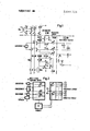
- FIG. 1 shows a switching circuit in accordance with the cir- I cuit arrangement of the invention connected in .a telephone installation of conventional construction employing preselectors and two-motion selectors; and
- I FIG. 2 shows a switching circuit inaccordance with the circuit arrangement of the invention connected with a telephone, exchange installation including a switching matrix of adhesion couplers for completing call connections, and wherein the information identifying each such call connection is stored in a connection storage means utilized for finding and selecting connections to be completed or switched-through the switching matrix.
- the preselectorcircuit shown in FIG. 1' is taken from the well-known telephone step switching selector dial system.
- The, method of operation of the preselector circuit of FIG. 1 is wellknown and therefore is not explained in detail, and the following description is limited to circuit modifications necessary for incorporating the system of the invention.
- a first group selector IGW is provided which includes a relay T2 (not shown) operating the contacts tz.
- the relay TZ responds at the termination of dialing a call connection signal from a calling subscriber to close its contacts tz. For example, and in a manner well known, if the subscriber Tn of FIG. 1 is connected in a completed call connection with another subscriber, then contacts 0, a, and tz are all actuated. Contact is actuated by relay C, and contact a is actuated relay A.
- the preselector circuit VW is 'operatively associated with the subdirected.
- relay 'R will 'respond as soonas the corresponding subscriber closes his subscriber loop in order to selecta connection.
- the winding Dof a rotary magnet is excited.
- Winding D of the rotary magnet of the preselector is connected on its otherside in the.
- a free first group selector is characterized by the fact that at its seizing circuit will lie a ground potential over winding C.
- relay T will respond. The latter relay will actuate contact 1! and 2t thereby disconnecting relay R.
- the call connection relay T will remain excited and relay R will remain unexcited. Again, all these switching.
- Relay P of line selector LW which normally serves to complete connection demands cannot respond to the new call connection demand to complete any switching under these circumstances.
- the contacts 1p and 2p of relay P remain in the normal positions indicated, and a circuit condition is established for transmission of an audible signal, represented by the transformer coupling and associated signal input labeled Hz is transmitted over the switching branches or contacts of the line selector LW which normally complete connections for the speaking paths.
- Thelline selector LW'further includes contacts lxy and 2xy which, in the foregoing discussion have been assumed to be in a closed position, or to be replaced by a direct connection. These contacts lxy and 2xy may be operated by conventional switching means responsive to a code signal transmitted by the calling, third subscriber to identify the subscriber connected in the original call connection to whom the new call is demanded by the unknown third subscriber, then each of the original subscribers may dial the digit 1, for example.
- the establishment of the intermediate answer connection for receiving the new call proceeds as follows.
- a signal at ground potential is applied to the test conductor extending to the group selector IGW from the preselector VW.
- relay R previously excited over its winding II by leakage current, is further excited to a sufficient level that it responds.
- the preconditioning or partial advance energization of the relay R renders its response time to this condition of contact a, extremely short.
- Thetest circuit'for the line selector LW is now connected to ground over contact Sr of the new energized relay R.
- Relay R excited for a short time by energization of its winding II, is now maintained energized in the test circuit over its winding I.
- Relay R as now energized, opens its associated contacts-1r and Zr thereby opening the original call connection.
- the original call connection is maintained, however, since the two partial windings of relay A of the first group selector IGW are connected in a series energizing circuit from a negative power terminal to a ground potential terminal through the now actuated, closed contacts Sr and 5t.
- Line selector LW is now prepared to perform a check.
- Relay P is energized and effects the necessary switching for completing the new call connection between the calling, third subscriber and the called subscriber Tn, illustratively by actuation of its associated contacts 1p and 2p.
- the checking process performed by line selector LW is controlled by, or dependent upon the switching or signalling operation produced in response to signalling by the third, culling subscriber.
- the abovementioned intermediate answer connection husbeen established between the calling, third subscriber and the subscriber Tn.
- the release of the intermediate answer connection is effected upon termination of the call connection by the calling, third subscriber.
- this termination requires merely that the calling, third subscriber replace his receiver and that the subscriber Tn of the original connection interrupt his loop circuit connection for a short time.
- This interruption is desirable to assure sufficient time for necessary switching operations.
- the test circuit including relay P in the line selector LW opens and permits relay R to drop out in accordance with a delayed response time.
- the contacts D and Zr then return to their normally closed positions and the original call connection is reestablished.
- FIG. 1 is but one example of such an embodiment, and serves merely to explain the principle of operation of the invention.
- Various details of the circuit operation have been omitted since they are not necessary to an explanation of the invention; these details include, for example, the method of charge accounting to be employed.
- FIG. 2 there is shown a telephone exchange installation having a switching circuit arrangement including a multistage switching matrix K and a marker M serving as a central control system.
- the marker M determines the path of completed call connections to be established and to be released within the matrix K.
- Such matrices are described in the Siemens Review, vol. 34 (1967) pages 226-230. For example, three such completed call connections, W1, W2, and W3 are illustrated within the matrix K.
- the installation further includes a storage system S having two major components, a subscriber storage means TS and a connection storage means VS. Such storage systems are fully described in Bell System Technical Journal, 1964, nos. 5 and 6, pages 1,836 and 2,l472,l9l.
- the subscriber storage means TS includes a plurality of subscriber storage rows TZl, TZ2, TZ 3,....
- connection storage means VS includes a plurality of connection storage rows VZl, VZ2, VZ3,....
- the subscriber and connection storage means include finders AT and AV, respectively, controlled by the marker M.
- the installation further includes a plurality of subscribers, two of which are represented as subscriber connections T1 and T2.
- a plurality of connection sets and other connection apparatus may be provided, illustrated by the connection set V having an inlet E and an outlet A for connection thereof to the matrix K.
- connection sets are described at page 227 in the aforementioned Siemens Review.
- a plurality of connection lines typically are connected to the matrix K, one of which is indicated in FIG. 2 to which a repeater U is connected.
- the connection lines may be local connection exchange lines, long distance lines, and the like.
- the matrix K provides for establishing connections in such a manner that two inputs of the switching matrix K which are to be connected with each other are connected to a single output of a switch.
- a coupler for completing such connections is provided in each switching stage of the switching matrix K. In this manner, call connections may be completed through the switching matrix K without requiring that the connection path include all possible switching stages. Minimizing the required number of switching stages is advantageous and contributes greater efficiency and higher speed to the operation.
- Connection W1 completes a call connection between subscriber T1 and the input terminal E of connection set V.
- Connection W2 completes a call connection between the output terminal A of the same connection set V and a subscriber T2.
- Subscriber Tl may represent a calling subscriber who has demanded a call connection to a subscriber T2 of the same exchange installation.
- the marker M establishes the connection paths W1 and W2 for connecting the connection set V to the subscriber station T1 to complete the call connection to the called subscriber station T2.
- a third connection W3 may be established by the marker M in response to a new call connection demand from a remote subscriber (not shown) connected to the switching matrix K by a transmission line repeater U.
- the connection W3 represents a demanded, or possibly completed, call connection to the subscriber T2 which is already engaged in the original call connection.
- Marker M also serves to control the finders AT and AV of the subscriber and connection storage means TS and VS, respectively, to provide access to the plurality of storage units TZl, TZ2,...VZ1,VZ2,.... These storage unit units or rows contain information necessary to the marker M in completing call connections within the matrix K.
- the subscriber storage rows TZl, TZ2,... store information corresponding to the subscriber stations and their current condition or participation in a call connection established or about to be established.
- the connection storage rows VZl, VZ2,... receive and register information corresponding to call connections.
- Two storage rows are required for recording the pertinent information regarding the call connection completed between two subscribers of the exchange installation.
- a first storage row such as VZl
- the second storage row such as VZ2
- Information regarding a connection between a subscriber, for example T2, and a connection line repeater, for example U, is registered in a single storage row such as VZ3 of the connection storage means VS.
- connection set V has completed the call connection through the connection paths W1 and W2 to the subscriber stations T1 and T2, respectively, as described above.
- connection storage row VZl there is registered the address of input E of connection set V, the program or path of connection W] in the switching matrix K, and the address of subscriber T1.
- connection storage row V22 there is registered the address of output A of connection set V, the program or path of connection W2 in the switching matrix K, and the address of subscriber T2.
- the rows VZl, VZ2,... of a connection means VS may be individually, and permanently assigned to the inputs and outputs of the connection sets and to the repeaters of th the installation.
- the registering of the address of the input or output terminals of the connection set participating in a call connection, or of a line repeater associated therewith, is not necessary, since this information will automatically be provided in accordance with the abovementioned information assignment of the storage rows.
- a third remote subscriber (not shown) establishes a call connection demand over repeater U to the subscriber T2.
- the third subscriber may, as a first possible operation, be authorized in advance to automatically complete a connection over connection path W3 to the subscriber T2.
- the third subscriber may, upon the receipt of a busy signal, and without first establishing connection path W3, cause an audible signal of the nature This audible signal may be transmitted or returned to T2 in many different ways.
- the audible signal may be transmitted to subscriber T2 during a brief interruption of the selects storage row VZ2 of connection storage means VS, corresponding to the output A of the connection set V, to be interrogated for completing the identification of the original call connection.
- connection W3 After connection W3 hasbeen released, and stored connection information in the storage row VZ2 relating thereto has connection W2 in the switching matrix K. ln this manner, only the desired called subscriber T2 of the original call connection receives the audible signal and subscriber T1 is isolated therefrom. Also as discussed previously, and in conjunction with the audible signal, the call identification code of the sub-v scriber may be presented in an automatic manner to indicate to the desired, called subscriber the identification of the third, calling subscriber.
- connection W3 required for establishing the new call connection demanded by the remote subscriber, either prior to and/or upon its completion, is registered in connection storage .row V23.
- This connection W3 includes identification of the address of line repeater U,
- subscriber T2 may transmit a readiness signal to the exchange to indicate preparedness for accepting the new call in an intermediate answer connection.
- the information contained in storage means S is thereupon interrogated.
- the readiness signal is received in the connection W2 of matrix K whereby the storage row of connection storage means VS correspond-.
- connection W2 ing to the connection W2 is interrogatedto identify the, address of the subscriber T2.
- the identification of subscriber T2 is registered in subscriber storage row T22.
- the row T22 is'interrogated and it is determined thereby that subscriber T2 is to be connected with a transmission line repeater U..
- Marker M responds to the information thus derived to complete the switching steps within matrix K for establishing the call connection W3.
- connection W3 will not be established if the remote, calling subscriber has releasedthe partial connection to the transmission line repeater U, prior to the called subscriber T2 acknowledging the new call demand and transmitting the readiness signal. If the remote subscriber terminates the partial connection, the information stored in connection storage row V23 is canceled. Since other connections may in the meantime be established over repeater U, subscriber T2 may not be connected with the repeater U.
- the subscriber storage rows T21, T22,... not only the address of the repeater U corresponding to the desirednew call connection or intrusion connection, and not only the inlet and outlet addresses of a connection set V, but also the address corresponding to the original call connection.
- the waiting signal as well as the address of subscriber T2 is selected from the storage row V23 when they connection storage means for interrogation in accordance with its assignment to the sub scriber T2, under consideration.
- the storage row TZ2 provides the address of the outlet A of connection set V over which the original connection proceeds.
- connection storage row V23 corresponding to repeater U
- an intermediate answersignal is stored, instead of the waiting signal as in the immediately foregoing discussion.
- connection storage row V22 corresponding to output A of connection set V there is registered a waiting signal instead of an intrusion signal.
- subscriber storage row T22 corresponding to subscriber T2
- the addresses of output A of connection set V and of repeater U remain in storage. These addresses therefore only change their places in storage row T22.
- the call connection W3 Upon releaseof the intermediate answer connection, the call connection W3 is opened. Marker M responds to the information in storage row V22 to recognize that the connection was an intermediate answer connection and that it was re lated to the subscriber T2 of the local exchange. Finder AT interrogates subscriber storage TS to identify the storage row T22 corresponding to the subscriber T2 under consideration.
- Marker M responds to the information stored in this row to connect the outlet A of connection set V to the subscriber T2.
- Marker M may complete this'connection either according to the original connection path in the matrix K or in accordance with any'other suitable path. If necessary, a new path-finding process and switching operation may be instituted for reestablishing a connection W2 to the subscriber T2. 1
- the nonpar- Y ticipating, original subscriber such as T1 may disconnect.
- connection W1 is opened whereby connection set V is released and the information contained in connection storage rows VZl and VZ2 is canceled.
- the call connection the corresponding connection storage rows VZl an and VZ2
- marker M receives from the latter the waiting signal and the address of subscriber T2.
- Marker M interrogates the subscriber storage means TS through the finder AT and determines from the storage row T22 assigned to subscriber T2 that the latter is in an intermediate answer connection proceeding over the repeater U.
- Marker M thereupon is connected to the connection storage means VS through the finder AV and cancels theintermediate answer connection information stored in the connection storage row V23.
- the call notification system of the invention provides a highly efiective and efficient operation of a telephone exchange installation to permit intrusion of new call demands on existing call connections.
- the intrusion is controlled at the option of the original calling subscriber, in recognition of the fact that the original calling subscriber is responsible for the expenses associated with the call connection.
- the original calling subscriber may accept the new call connection demand in an intermediate answer connection wherein the original connection is maintained in a standby condition ready to be automatically reinstated upon termination of the intermediate answer connection.
- an indication of a new call connection demand is provided to both of the original, calling and called subscribers, and the indication may specify which of the original subscribers is being requested.
- the system of the invention provides substantially completely automatic operation for responding to new call connection demands while preventing any unauthorized or undesired interference with existing call connections.
- a circuit arrangement for a telephone installation for notifying subscribers engaged in an original call connection of the existence of a new call connection demand from a further subscriber and for processing the new call connection demand comprising:
- authorization means operable by an original subscriber receiving a new call indication from said response means to authorize receipt of the new call
- control means responsive to the new call receipt authorization of an original subscriber to complete an intermediate answer connection between said further subscriber and said original subscriber in accordance with said new call connection demand while preserving the original call connection in an open condition;
- control means automatically reestablishing said original call connection upon termination of said intermediate answer connection.
- said subscribers engaged in said original call connection include calling and called subscribers;
- control means comprises a switching matrix and a central control system for controlling the switching operations in the matrix tocomplete call connections.
- connection storage means having a pluralit of storage units for storing an identification of the pa of a corresponding completed call connection in the matrix
- said storage means further includes scanning means for interrogating said plurality of storage units to identify the path of each completed connection, and for identifying each storage unit associated with a completed call connection to cancel the information registered therein upon final termination of the call connection.
- said central control system includes means for opening the connections in the switching matrix for the original call connection at the initiation of an intermediate answer connection;
- connection storage includes means for preserving the storage of the identification of the paths of the original call connection for the duration of the intermediate answer connection.
- said scanning means is responsive to termination of the intermediate answer connection to interrogate said storage units identifying the path of the intermediate answer connection to identify the storage units registering the connection path of the corresponding original call connection;
- said central control system is responsive to the information derived from the latter storage units to reestablish the original call connection.
- said central control system further includes means for indicating a standby condition
- said standby condition indicating means supplements said latter storage units for indicating the continued connection of an original called subscriber in an open condition of the original call connection.
- said central control system includes a plurality of connection systems, operable to establish call connections;
- selected ones of said plurality of storage units are permanently and individually assigned to corresponding connection systems.
- control means temporarily interrupts said original call connection to permit selective transmission of the audible signal by said transmitting means to the called one of the original subscribers.
Landscapes
- Engineering & Computer Science (AREA)
- Computer Networks & Wireless Communication (AREA)
- Exchange Systems With Centralized Control (AREA)
- Telephonic Communication Services (AREA)
- Telephone Function (AREA)
Applications Claiming Priority (1)
| Application Number | Priority Date | Filing Date | Title |
|---|---|---|---|
| DES106239A DE1263864B (de) | 1966-09-29 | 1966-09-29 | Schaltungsanordnung fuer Fernmeldevermittlungsanlagen, insbesondere Fernsprechnebenstellenanlagen, in welchen belegte Teilnehmerstellen von dem Vorliegen eines neuen Anrufes verstaendigt werden |
Publications (1)
| Publication Number | Publication Date |
|---|---|
| US3544725A true US3544725A (en) | 1970-12-01 |
Family
ID=7527248
Family Applications (1)
| Application Number | Title | Priority Date | Filing Date |
|---|---|---|---|
| US670629A Expired - Lifetime US3544725A (en) | 1966-09-29 | 1967-09-26 | Exchange arrangement permitting temporary call suspension for acceptance of a new call |
Country Status (8)
| Country | Link |
|---|---|
| US (1) | US3544725A (xx) |
| AT (1) | AT281128B (xx) |
| BE (1) | BE704487A (xx) |
| CH (1) | CH482371A (xx) |
| DE (1) | DE1263864B (xx) |
| GB (1) | GB1187959A (xx) |
| NL (1) | NL6712578A (xx) |
| SE (1) | SE338794B (xx) |
Cited By (1)
| Publication number | Priority date | Publication date | Assignee | Title |
|---|---|---|---|---|
| US3609245A (en) * | 1968-05-21 | 1971-09-28 | Int Standard Electric Corp | Arrangement for enabling an existing call to be temporarily interrupted |
Families Citing this family (1)
| Publication number | Priority date | Publication date | Assignee | Title |
|---|---|---|---|---|
| DE2907194C2 (de) * | 1979-02-23 | 1985-08-22 | Siemens AG, 1000 Berlin und 8000 München | Schaltungsanordnung für Fernsprech- und Fernsprechnebenstellenanlagen mit Auswertung von aus einer Gegenanlage eintreffenden Sonderkennzeichen (Trennen durch Fernamt) |
-
1966
- 1966-09-29 DE DES106239A patent/DE1263864B/de not_active Withdrawn
-
1967
- 1967-06-26 SE SE09197/67*A patent/SE338794B/xx unknown
- 1967-09-14 NL NL6712578A patent/NL6712578A/xx unknown
- 1967-09-26 US US670629A patent/US3544725A/en not_active Expired - Lifetime
- 1967-09-27 CH CH1357967A patent/CH482371A/de not_active IP Right Cessation
- 1967-09-27 AT AT878567A patent/AT281128B/de not_active IP Right Cessation
- 1967-09-28 GB GB44154/67A patent/GB1187959A/en not_active Expired
- 1967-09-29 BE BE704487D patent/BE704487A/xx unknown
Cited By (1)
| Publication number | Priority date | Publication date | Assignee | Title |
|---|---|---|---|---|
| US3609245A (en) * | 1968-05-21 | 1971-09-28 | Int Standard Electric Corp | Arrangement for enabling an existing call to be temporarily interrupted |
Also Published As
| Publication number | Publication date |
|---|---|
| CH482371A (de) | 1969-11-30 |
| SE338794B (xx) | 1971-09-20 |
| AT281128B (de) | 1970-05-11 |
| DE1263864B (de) | 1968-03-21 |
| GB1187959A (en) | 1970-04-15 |
| BE704487A (xx) | 1968-03-29 |
| NL6712578A (xx) | 1968-04-01 |
Similar Documents
| Publication | Publication Date | Title |
|---|---|---|
| US3573377A (en) | Equipment to coordinate establishment of audio and video connections through switching systems | |
| US4232198A (en) | Device for establishing conference calls via at least one telephone exchange switching system | |
| US3542961A (en) | Call forwarding equipment for operators | |
| US3544725A (en) | Exchange arrangement permitting temporary call suspension for acceptance of a new call | |
| US2335481A (en) | Telephone system | |
| US3491213A (en) | Two-way trunk circuit | |
| US3673341A (en) | Call re-routing system for telephone installations | |
| US2056752A (en) | Automatic telephone system | |
| US3456081A (en) | Pay station collect and return system | |
| US3427404A (en) | Switching arrangement for a telephone installation | |
| US2976368A (en) | Incoming trunk circuit for in-dialing service | |
| US3818144A (en) | Multifrequency to dial pulse signal converter | |
| US1979020A (en) | Telephone exchange system | |
| US1727137A (en) | Automatic telephone system | |
| US3588370A (en) | Switching circuit to control call number transmitters in automatic telephone systems | |
| US2299514A (en) | Telephone system | |
| US1799654A (en) | Telephone-exchange system | |
| USRE22476E (en) | Telephone system | |
| US3505481A (en) | Subscriber-effected automatic redialing for paths-busy conditions | |
| US2792453A (en) | Automatic telephone system of the relay type | |
| US1658829A (en) | Telephone system | |
| US2090171A (en) | Telephone system | |
| US2020458A (en) | Telephone system | |
| US4058684A (en) | Apparatus for direct line switching | |
| US1811844A (en) | Automatic telephone exchange system |