US3540407A - Monitoring positive crankcase ventilating systems in internal combustion engines - Google Patents
Monitoring positive crankcase ventilating systems in internal combustion engines Download PDFInfo
- Publication number
- US3540407A US3540407A US790136A US3540407DA US3540407A US 3540407 A US3540407 A US 3540407A US 790136 A US790136 A US 790136A US 3540407D A US3540407D A US 3540407DA US 3540407 A US3540407 A US 3540407A
- Authority
- US
- United States
- Prior art keywords
- flap
- internal combustion
- positive crankcase
- combustion engines
- crankcase ventilating
- Prior art date
- Legal status (The legal status is an assumption and is not a legal conclusion. Google has not performed a legal analysis and makes no representation as to the accuracy of the status listed.)
- Expired - Lifetime
Links
- 238000012544 monitoring process Methods 0.000 title description 10
- 238000002485 combustion reaction Methods 0.000 title description 8
- 238000000034 method Methods 0.000 description 2
- 241000220010 Rhode Species 0.000 description 1
- 238000004140 cleaning Methods 0.000 description 1
- 238000010276 construction Methods 0.000 description 1
Images
Classifications
-
- F—MECHANICAL ENGINEERING; LIGHTING; HEATING; WEAPONS; BLASTING
- F01—MACHINES OR ENGINES IN GENERAL; ENGINE PLANTS IN GENERAL; STEAM ENGINES
- F01M—LUBRICATING OF MACHINES OR ENGINES IN GENERAL; LUBRICATING INTERNAL COMBUSTION ENGINES; CRANKCASE VENTILATING
- F01M13/00—Crankcase ventilating or breathing
- F01M13/02—Crankcase ventilating or breathing by means of additional source of positive or negative pressure
Definitions
- a device for monitoring a positive crankcase ventilating system associated with an internal combustion engine having an oil intake pipe connected to a crankcase has a sheetlike member with an opening therethrough and a flap, withits longest dimension smaller than the smallest dimension of the mouth of the pipe, hinged to the member and normally covering substantially all of the opening.
- Objects of the invention are to provide for such monitoring with a device that is of simple construction, is easily and inexpensively made and used, is reliable, and is conducive to use at desirable frequency by automobile operators.
- the invention features a device for monitoring a positive crankcase ventilating system associated with an internal combustion engine having an oil intake pipe connected to a crankcase, the device having a sheetlike member with an opening therethrough and a flap hinged to the member and normally covering substantially all of the opening, the flap having its longest dimension smaller than the smallest dimension of the mouth of the pipe.
- the flap has a trapezoidal shape; the flap is hinged along its shorter base; the length of the longer base of the flap is more than twice the length of the shorter base of the flap; the bases are separated from each other by a distance greater than the length of the longer base; the opening has a slightly larger area than the flap and provides a clearance space between the inner edge of the opening and the unhinged sides and longer base of the-flap; the sheetlike member has a flexible portion and the flap is integral with the flexible portion at the hinge; the flexible portion is constructed of thin paper; the length of the shorter 'base is such that a small pressure differential across the flap will deflect the flap about its hinge; the sheetlike member has two separable portions, one of which includes the flap; the flap carries an indicator; and the indicator is an arrow.
- the invention features a method of monitoring a positive crankcase ventilating system associated with an internal combustion engine having an oil intake pipe connected to a crankcase, the method having the steps of providing a sheetlike member flexible over at least a portion thereof and having an opening in the flexible portion and a flap hinged to the member and normally covering substantially all of the opening, the flap having its longest dimension smaller than the shortest dimension of the mouth of the pipe, and placing the member over the mouth with the flap in registry with the mouth while the engine is running.
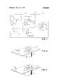
- FIG. 1 is a plan view of the testing device included as a portion of an advertising and instructional sheet
- FIG. 2 is a perspective view of the device in use when the ventilator is-operating properly.
- FIG. 3 is a perspective view of the indicating device in use when the ventilator is clogged.
- rectangular paper sheet (2 mils thick) is perforated along line 12 and has circle 14 in the center of smaller portion 16.
- Sheet 10 is die cut within circle 14 to provide trapezoidal flap l8 hinged to sheet 10 along its shorter base (0.187 inches long).
- Longer base 22 is parallel to and more than twice as long (0.406 inches) as base 20 and is separated therefrom by a distance (0.625 inches) greater than its own length.
- Clearance space 24 (0.015 to 0.020
- portion 12 In operation, to monitor the positive crankcase ventilating system, portion 12 is separated from portion 32 and circle 14 is placed over the opening of pipe 34 while the automobile engine is running.
- a device for monitoring a positive crankcase ventilating system associated with an internal combustion engine having an oil intake pipe connected to a crankcase comprising:
- a device wherein said opening has an inner edge and has a slightly larger area than said flap and said flap has a trapezoidal shape, is hinged along its shorter base and has unhinged sides and longer base:
- said longer base having a length greater than twice the length of said shorter base and being parallel to and separated from said shorter base by a distance greater than the length of said longer base;
- said opening providing a clearance space between said inner edge of said opening and said longer base and sides of said flap.
- said sheetlike member includes a flexible portion, said flap being integral with said flexible portion at said hinge.
- a device according to claim 5 wherein said flexible portion is constructed of thin paper.
- a device according to claim 3 wherein the length of said shorter base is adapted to permit a small predetermined pressure differential across said flap to deflect said flap about its hinge.
Landscapes
- Engineering & Computer Science (AREA)
- Mechanical Engineering (AREA)
- General Engineering & Computer Science (AREA)
- Lubrication Details And Ventilation Of Internal Combustion Engines (AREA)
Description
United States Patent Inventors Francis L. McGonagle,
Swansea, Massachusetts; Earle 1'1. Fulford, Barrington, Rhode Island Appl. No. 790,136 Filed Jan. 9, 1969 Patented Nov. 17, 1970 Assignee Fram Corporation East Providence, Rhode Island a corporation of Delaware MONITORING POSITIVE CRANKCASE VENTILATING SYSTEMS IN INTERNAL COMBUSTION ENGINES 7 Claims, 3 Drawing Figs.
U.S. Cl 116/70, 1 16/1 14 Int. Cl G011 19/12 Field of Search 1 16/70,
References Cited UNITED STATES PATENTS 7/1877 Spethmann 568,124 9/1896 Wojciechowski 84/363 1,535,688 4/1925 Sauer 1l6/70X 2,413,126 12/1946 Warburton... 116/124X 2,655,894 10/1953 Rabbitt 116/117 3,246,624 4/1966 Lowther 116/70 3,312,187 4/1967 McKinlay 116/70 3,330,248 7/1967 Cornell 73/388X 3,442,125 5/1969 Foley 73/228 FOREIGN PATENTS 500,265 3/1954 Canada 116/124 Primary Examiner-Louis J. Capozi Att0rneyW. R. l-Iulbert ABSTRACT: A device for monitoring a positive crankcase ventilating system associated with an internal combustion engine having an oil intake pipe connected to a crankcase, has a sheetlike member with an opening therethrough and a flap, withits longest dimension smaller than the smallest dimension of the mouth of the pipe, hinged to the member and normally covering substantially all of the opening.
- Patented Nov. 17, 197 0 IF YOUR SYSTEM VALVE I5 PLUGGED MONITORING POSITIVE CRANKCASE VENTILATING SYSTEMS IN INTERNAL COMBUSTION ENGINES This invention relates to monitoring positive crankcase ventilating systems in internal combustion engines.
Objects of the invention are to provide for such monitoring with a device that is of simple construction, is easily and inexpensively made and used, is reliable, and is conducive to use at desirable frequency by automobile operators.
In one aspect the invention features a device for monitoring a positive crankcase ventilating system associated with an internal combustion engine having an oil intake pipe connected to a crankcase, the device having a sheetlike member with an opening therethrough and a flap hinged to the member and normally covering substantially all of the opening, the flap having its longest dimension smaller than the smallest dimension of the mouth of the pipe. In preferred embodiments the flap has a trapezoidal shape; the flap is hinged along its shorter base; the length of the longer base of the flap is more than twice the length of the shorter base of the flap; the bases are separated from each other by a distance greater than the length of the longer base; the opening has a slightly larger area than the flap and provides a clearance space between the inner edge of the opening and the unhinged sides and longer base of the-flap; the sheetlike member has a flexible portion and the flap is integral with the flexible portion at the hinge; the flexible portion is constructed of thin paper; the length of the shorter 'base is such that a small pressure differential across the flap will deflect the flap about its hinge; the sheetlike member has two separable portions, one of which includes the flap; the flap carries an indicator; and the indicator is an arrow.
In another aspect the invention features a method of monitoring a positive crankcase ventilating system associated with an internal combustion engine having an oil intake pipe connected to a crankcase, the method having the steps of providing a sheetlike member flexible over at least a portion thereof and having an opening in the flexible portion and a flap hinged to the member and normally covering substantially all of the opening, the flap having its longest dimension smaller than the shortest dimension of the mouth of the pipe, and placing the member over the mouth with the flap in registry with the mouth while the engine is running.
Other objects, features and advantages will appear from the following description of a preferred embodiment of the invention, taken together with the attached drawings thereof, in which:
FIG. 1 is a plan view of the testing device included as a portion of an advertising and instructional sheet;
FIG. 2 is a perspective view of the device in use when the ventilator is-operating properly; and
FIG. 3 is a perspective view of the indicating device in use when the ventilator is clogged.
Referring to FIG. 1, rectangular paper sheet (2 mils thick) is perforated along line 12 and has circle 14 in the center of smaller portion 16. Sheet 10 is die cut within circle 14 to provide trapezoidal flap l8 hinged to sheet 10 along its shorter base (0.187 inches long). Longer base 22 is parallel to and more than twice as long (0.406 inches) as base 20 and is separated therefrom by a distance (0.625 inches) greater than its own length. Clearance space 24 (0.015 to 0.020
, inches wide) is provided between flap 18 at sides 26 and 28 and base 22 and the remaining portion of sheet 16. An arrow 30 is printed on flap 18. Advertising and instructions for monitoring a positive crankcase ventilator system in an automobile are printed on the longer portion 32 of sheet 10.
As is known (see, e.g., U.S. Pat. No. 3,330,248), when a positive crankcase ventilating system is clogged, a slightly super-atmospheric pressure, instead of the normal subatmospheric pressure, will appear in the oil intake pipe 34 (FIGS. 2, 3) to the crankcase in the automobile.
In operation, to monitor the positive crankcase ventilating system, portion 12 is separated from portion 32 and circle 14 is placed over the opening of pipe 34 while the automobile engine is running.
If the positive crankcase ventilating system is operating satisfactorily, a pressure differential sufficient (as determined by the length of base 22) to deflect flap 18 about its hinge will appear at the opening of pipe 34 and will draw flap 18 into pipe 34. If the positive crankcase ventilating system is clogged, flap 18 will bend upwardly, arrow 22 thereby appearing to indicate the need for replacement or cleaning.
We claim:
1. A device for monitoring a positive crankcase ventilating system associated with an internal combustion engine having an oil intake pipe connected to a crankcase, comprising:
a nonmetallic sheetlike member having an opening therethrough; and
a flap hinged to said member, and normally covering substantially all of said opening, said flap having its longest dimension smaller than the smallest dimension of the mouth of said pipe.
2. A device according to claim 1 wherein said flap has a trapezoidal shape.
3. A device according to claim 2 wherein said flap is hinged along its shorter base.
4. A device according to claim 1 wherein said opening has an inner edge and has a slightly larger area than said flap and said flap has a trapezoidal shape, is hinged along its shorter base and has unhinged sides and longer base:
said longer base having a length greater than twice the length of said shorter base and being parallel to and separated from said shorter base by a distance greater than the length of said longer base; and
said opening providing a clearance space between said inner edge of said opening and said longer base and sides of said flap.
5. A device according to claim 1 wherein said sheetlike member includes a flexible portion, said flap being integral with said flexible portion at said hinge.
6. A device according to claim 5 wherein said flexible portion is constructed of thin paper.
7. A device according to claim 3 wherein the length of said shorter base is adapted to permit a small predetermined pressure differential across said flap to deflect said flap about its hinge.
Applications Claiming Priority (1)
| Application Number | Priority Date | Filing Date | Title |
|---|---|---|---|
| US79013669A | 1969-01-09 | 1969-01-09 |
Publications (1)
| Publication Number | Publication Date |
|---|---|
| US3540407A true US3540407A (en) | 1970-11-17 |
Family
ID=25149746
Family Applications (1)
| Application Number | Title | Priority Date | Filing Date |
|---|---|---|---|
| US790136A Expired - Lifetime US3540407A (en) | 1969-01-09 | 1969-01-09 | Monitoring positive crankcase ventilating systems in internal combustion engines |
Country Status (1)
| Country | Link |
|---|---|
| US (1) | US3540407A (en) |
Cited By (1)
| Publication number | Priority date | Publication date | Assignee | Title |
|---|---|---|---|---|
| US3736900A (en) * | 1972-01-10 | 1973-06-05 | R Nowicki | Carburetor air intake filters |
-
1969
- 1969-01-09 US US790136A patent/US3540407A/en not_active Expired - Lifetime
Cited By (1)
| Publication number | Priority date | Publication date | Assignee | Title |
|---|---|---|---|---|
| US3736900A (en) * | 1972-01-10 | 1973-06-05 | R Nowicki | Carburetor air intake filters |
Similar Documents
| Publication | Publication Date | Title |
|---|---|---|
| US2055853A (en) | Separator for filter type respirators | |
| ES293149U (en) | Member for indicating clogging of the air intake filter, particularly for motor vehicle engines. | |
| FR2428851A1 (en) | PROTECTION DEVICE FOR OPTICAL ELEMENT | |
| KR860000550A (en) | Differential pressure detector assembly | |
| US3246624A (en) | Pressure indicating device | |
| GB1333590A (en) | Dust leak detector for air cleaner systems | |
| JPS6039045U (en) | Device for removing ammonia vapor emitted from diazo copiers | |
| US3540407A (en) | Monitoring positive crankcase ventilating systems in internal combustion engines | |
| BR7903397A (en) | CUP SET, FOR A COMPRESSED AIR OR GAS FILTER OR LUBRICATOR, COMPRESSED AIR OR GAS FILTER OR LUBRICATOR, HARD EXTERNAL CUP AND FLEXIBLE INTERNAL CUP | |
| KR830006571A (en) | Engine intake | |
| KR850003931A (en) | Fuel injection device | |
| US3397395A (en) | Filter condition indicator | |
| US2577607A (en) | Air supply system for welders' helmets | |
| US3381651A (en) | Fluid filter assembly having a warning indicator | |
| JPS59107903U (en) | Trailing edge blowout cooling vane | |
| US1535688A (en) | Engine pressure register | |
| US2509802A (en) | Cleaner construction | |
| KR940006628A (en) | Operation Control System of Dust Collector | |
| US5759492A (en) | End of life monitor for a gas filter | |
| FR1038158A (en) | Valve or valve particularly intended for a device for maintaining the full air in a liquid tank at air pressure | |
| GB909034A (en) | Improvements in or relating to sound or noise producing devices, particularly applicable to filter assemblies | |
| US2068900A (en) | Horn | |
| US1435173A (en) | Quick-changing mute for band instruments | |
| US1670200A (en) | Attachment for motor exhausts | |
| US2066001A (en) | Actuating mechanism for warning signals |