US3534184A - Rotary switch equipped with shiftable shaft for lifting wiper arms - Google Patents
Rotary switch equipped with shiftable shaft for lifting wiper arms Download PDFInfo
- Publication number
- US3534184A US3534184A US784867A US3534184DA US3534184A US 3534184 A US3534184 A US 3534184A US 784867 A US784867 A US 784867A US 3534184D A US3534184D A US 3534184DA US 3534184 A US3534184 A US 3534184A
- Authority
- US
- United States
- Prior art keywords
- shaft
- wafer
- wiper arms
- switch
- assembly
- Prior art date
- Legal status (The legal status is an assumption and is not a legal conclusion. Google has not performed a legal analysis and makes no representation as to the accuracy of the status listed.)
- Expired - Lifetime
Links
Images


Classifications
-
- H—ELECTRICITY
- H01—ELECTRIC ELEMENTS
- H01H—ELECTRIC SWITCHES; RELAYS; SELECTORS; EMERGENCY PROTECTIVE DEVICES
- H01H25/00—Switches with compound movement of handle or other operating part
- H01H25/06—Operating part movable both angularly and rectilinearly, the rectilinear movement being along the axis of angular movement
Definitions
- FIG/0 was uuuu United States Patent 3,534,184 ROTARY SWITCH EQUIPPED WITH SHIFTABLE SHAFT FOR LIFTING WIPER ARMS Michael A. Tabet, 1336 Ballentine Blvd., Norfolk, Va. 23504 Filed Dec. 18, 1968, Ser. No. 784,867 Int. Cl. H01h 9/00 US. Cl. 2004 4 Claims ABSTRACT OF THE DISCLOSURE
- An electrical switch of the rotary type wherein wiper arms are moved to overlie circumferentially spaced contacts by rotation of a shaft.
- a cam and a cam follower between the shaft and the wiper arms serves to lift the wiper arms from the contacts when the shaft is shifted in the direction of its axis.
- the shaft is releasably retained in each of its shifted positions.
- the present invention relates to a switch of the type wherein wiper arms are moved in an arcuate path by rotation of a shaft to overlie circumferentially spaced contacts carried by a wafer element.
- the invention more specifically pertains to a switch assembly wherein the shaft may be moved in the direction of its axis including cam means between the shaft and the wiper arms for lifting the wiper arms from contacts on the wafer element and to urge the wiper arms into engagement with contacts on the wafer element.
- Another object of the invention is to provide means in association with the axially movable shaft which serves to prevent rotation of the shaft when it is in one position with the means so constructed that the shaft may be rotated in another axial position of the shaft.
- a further object of the invention is to provide means releasably maintaining the shaft of the switch assembly in each of its two axially shifted positions.
- Another object of the invention is to provide an indicator which serves to provide a discernable indication of the rotated position of the wiper arms when the shaft of the switch assembly is in a position where it is releasably restrained from rotation.
- FIG. 1 is a perspective view of the switch assembly embodying the invention with one of the wafer units removed from the frame and showing the shaft and portions of the detent assembly.
- FIG. 2 is a similar view illustrating another type of wafer element and showing the structure whereby a group may be supported on the switch frame.
- FIG. 3 is an exploded perspective view of a wafer element and the parts which make up the rotor and the wiper arms.
- FIG. 4 is a sectional View of a rotor and wiper arm unit with the parts separated to clarify the structure.
- FIG. 5 is a transverse sectional view through a wafer element showing a rotor unit mounted thereon.
- FIG. 6 is a fragmentary sectional view taken on the line 66 of FIG. 5.
- FIG. 7 is a view similar to FIG. 5 illustrating the position of the wiper arms when the cam follower is engaged by the cam element carried by the shaft.
- FIG. 8 is a plan view of the frame shown in FIG. 1 illustrating the cam elements carried by the shaft and with the wafer elements removed.
- FIG. 9 is a side elevational view of the switch frame shown in FIG. 8 and partially in section.
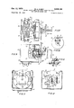
- FIG. 10 is a sectional view taken on the line 1010 of FIG. 9.
- FIG. 11 is an end elevational view showing the dial and the device for indicating the rotated position of the switch shaft.
- FIG. 12 is a sectional view taken on the line 12--12 of FIG. 8.
- FIG. 13 is a fragmentary view of a portion of the shaft and the detent associated therewith.
- FIG. 14 is a view illustrating another modification of the present invention.
- the present invention pertains to a switch of the type where wiper arms are rotated to overlie circumferentially spaced contacts and a feature of the switch pertains to structure which permits the shaft 21 to be moved in axial directions to assume an Inner and Outer position and the mechanism is so constructed that the shaft may be rotated only when it is in its Outer position.
- the shaft 21 as shown in FIGS. 1 and 8 is of such length as to extend through a plurality of juxtaposed wafer elements and a disc assembly 22 mounted for rotation in an opening in an end plate 23 provides a journal for the inner end of the shaft.
- the shaft 21 is of elongated rectangular shape in cross section as shown in FIG. 12 throughout the portion which serves to rotate wiper arms carried on each wafer element.
- a notched wheel 24 is attached to the shaft 21 adjacent an end plate 26.
- the wheel 24 has notches 27 in the periphery which cooperate with a roller 28.
- the roller 28 is carried by a lever 29 which is pivoted at 30 (FIG. 12) on the plate 26 and a spring 31 urges the roller 28 into a notch 27 to releasably retain the shaft 21 in one of its indexed positions.
- the outer end portion 33 (FIG. 9) of the shaft is generally of cylindrical formation and is journaled for rotation with respect to the end plate 26 by a bearing member 32.
- An annular groove 34 is provided in the cylindrical portion 33 of the shaft.
- a ball 35 mounted in the bearing member 32 is resiliently urged into the annular groove 34 by a leaf spring 36 to releasably hold the shaft in its Outer position.
- An extension 37 of the shaft projects through a dial 38 and a knob 39 is mounted on the free end of the extension 37. When the knob 39 is moved towards the switch frame and when the shaft assembly is in its Inner position, the ball 35 engages the peripheral portion 41 of the shaft extension 37 outwardly of the annular flange 40 (FIG. 13) to releasably maintain the shaft in its Inner position.
- Means is provided for preventing rotation of the shaft assembly when it is in the Inner position.
- Such means includes an abutment member 43 mounted on the plate 26.
- a slot 44 extending substantially parallel to the shaft is provided in the abutment member 43 for accommodating one of the teeth 46 on the wheel 24.
- the slot 44 is so disposed in relationship to the detent assembly that when the shaft is in one of its indexed positions it may be shifted to its Inner position during which a tooth 46 is accommodated in the slot 44.
- the walls defining the slot 44 form a shoulder at each side of the tooth 46 so that the knob 39 and the shaft 21 can not be rotated after the shaft assembly assumes its Inner position.
- the abutment member 43 is provided with an open area 48 adjacent the plate 26.
- the dial 38 is provided with circumferentially spaced indices corresponding in number to the number of notches 27 in the wheel 24.
- a bifurcated member 51 is mounted for pivoting movement about a pin 52 on the knob 39 (FIG. 9).
- a leaf spring 53 anchored on the knob 39 engages a portion of the bifurcated member 51 and urges it in a counter-clockwise direction about the pin 52 when the shaft assembly is in the Outer position.
- the knob 39 and the shaft assembly is shifted to the Inner position the free ends of the bifurcated member 51 engage the outer face of the dial 38 and swings this member in a clock-wise direction from the position shown in FIG. 9 so that end portions of the member '51 are discernible from the front of the switch assembly as shown in FIG. 11.
- the bifurcated member 51 desirably spans one of the indices on the dial 38 thereby indicating the indexed position of the shaft assembly, and further indicating that the shaft cannot be rotated.
- the spring 53 biases the bifurcated member 51 to a position where it is not visible when viewing the switch assembly from a position outwardly of the knob 39.
- the frame of the switch may accommodate a plurality of wafer elements each carrying a rotor adapted to be driven and rotated by the shaft portion 21 when the shaft assembly is in the Outer position.
- the switch frame is shaped to receive one or more wafer elements 53 (FIG. 1) each having a slot 54 therein extending from one edge to a central opening through the wafer.
- Such a wafer element is adapted to be guided in grooves 56 which are aligned transversely of the frame as best shown in FIG. 8.
- the slot 54 accommodates the portion 21 of the shaft as the wafer element is moved intothe frame with the edge portions guided by two slots 56.
- the wafer elements carry electrical conductors 57 which may be applied to both faces thereof in a printing circuit process.
- the wafer elements 63 are supported on the plate 26 of the frame by means of bolts 64 and spacer elements 66.
- the wafer elements 63 are each devoid of a slot '54.
- Conductors 57 on the faces of the wafer elements 63 engage contacts 58 of multiple contact recepticles of the type shown at 60 in FIG. 8.
- Terminals 55 of the multiple contact recepticles project outside the frame of the switch and are adapted to be connected to conductors leading to the circuits to be controlled.
- a feature of the invention pertains to the rotors which are mounted on each wafer element and journaled for rotation within a relatively large cylindrical opening 68 formed in each type of wafer element.
- One disc shaped element 71 has a peripheral surface 72 adapted to fit within the opening 68.
- a peripheral flange 73 (FIG. 5) on the disc element 71 overlies the face of the wafer.
- a similar disc element 74 is provided with a cylindrical surface 76 which is also accommodated within the opening 68.
- a flange 77 on the disc element 74 overlies the opposite face of the wafer.
- the disc elements 71 and 74 are attached to each other by means of rivets 78 which extend through registering openings in the two disc elements.
- a wiper arm unit 81 is associated with the disc 71 and a wiper arm unit 82 is associated with the disc element 74.
- Some of the rivets 78 which extend through both disc elements serve to hold the wiper arms in operative relationship with opposite faces of wafer elements.
- Each rotor is equipped with and substantially encases a cam follower 84.
- the cam follower 84 is accommodated within a recess 86, in the disc element 71 and a recess 87 in the disc element 74.
- Tongues one of which is shown at 88 in FIG. 3, serve to guide the follower in directions radially of the rotor unit.
- a shoulder 91 in the disc element 71 and a shoulder 92 in the disc element 74 limit the radial inward movement of the follower 88.
- a cavity 94 within the follower 84 accommodates an end portion of a helical spring 96.
- An inverted cup-shaped member 97 houses the other end of the spring 96.
- the member 97 is in abutting relationship with a surface 98 in the disc element 71 and in abutting relationship with a surface 99 in the disc element 74.
- the cam follower 84 is urged radially towards the axis of the rotor and towards the axis of the rotor and towards the shoulders 91 and 92.
- the portion 21 of the shaft carries cams which in number correspond to the number of wafer elements and two cams 101 and 102 are shown in FIGS. 1 and 8. Each of these cams has an inclined portion 103 (FIG. 5) and a surface 104- which is substantially parallel to the axis of the shaft.
- each cam 101 is in an inactive position relative to the associated cam follower 84.
- the helical spring 96 is then in an extended position.
- a lug 106 is provided on one side of the cam follower and a lug 107 is provided on the other side.
- the wiper arm assemblies 81 and 82 are each provided with a proturbance 112 and 114 as best shown in FIG. 4.
- the lugs 106 and 107 engage these proturbances when the cam follower is in the inactive position shown in FIG. 5, and the wiper arm assemblies 81 and 82 are moved away from opposite faces of the wafer element and accordingly disengage the contacts or conductors on opposite faces of wafer.
- the shaft assembly is shifted to its Inner position the cam surface 103 first engages the inner end of the cam follower 84 and moves it radially from the axis of the shaft compressing the spring 96.
- the lugs 106 and 107 are thus displaced from the proturbances 112 and 114, whereby the wiper arms which are of the leaf spring type engage contacts at opposite faces of the wafer element.
- the shaft assembly can only be rotated when it is in the Outer position.
- the wiper arms are disengaged from contacts on the wafer element or elements during rotation of the rotor or rotors to another indexed position.
- the shaft assembly is shifted to its Inner position and the bifurcated member 51 indicates the new indexed position.
- a tooth 46 is then accommodated in the slot 44 and the shaft assembly is restrained from rotation.
- the ball 35 then overlies the periphery of the shaft extension 37 (FIG. 13) and releasably retains the shaft assembly in its Inner position.
- the proturbances 112 and 114 may be so located on the wiper arm assemblies 81 and 82 as to shift the wiper arms from engagement with contacts or conductors carried by the opposite faces of the wafer elements when the shaft assembly is in the Inner position and such a relationship of the parts is shown in FIG. 14.
- the proturbance 112 may be located as shown in FIGS. 5 and 7 and the proturbance 114 may be located as shown in FIG. 14.
- the wiper arm 81 will then be lifted from the contact on one face of the wafer element and the wiper arm 82 will be in engagement with the contact on the other face of the wafer element in the Outer position of the shaft.
- An electrical switch comprising, a frame, means supporting a wafer element on said frame, conductors and circumferentially spaced contacts on a face of said wafer element, a rotor mounted for rotation on said wafer element, wiper arm means carried by said rotor for overlying said contacts, a shaft mounted for rotation on said frame extending into driving relationship with said rotor, a cam carried by said shaft adjacent said rotor, a cam follower carried by said rotor adjacent said wiper arm means and movable relative to the rotor, resilient means urging the cam follower toward said shaft, a proturbance on the wiper arm means adapted to be engaged by said cam follower in one position thereof to move the wiper arm means from engagement with said contacts, and said shaft being shiftable in directions of its axis for moving said cam into operative engagement with said cam follower.
- An electrical switch according to claim 1 including means for releasably holding the shaft in each of its shifted positions.
Description
M. A. TABET Oct. 13, 1970 3,534,184 ROTARY SWITCH EQUIPPED WITH SHIFTABLE SHAFT FOR LIFTING WIPER ARMS 3 Sheets-Sheet 1 Filed Dec. 18, 1968 INVENTOR mama. A. raasr BY Q I l T. AibR/VEY Oct. 13, 1970 M. A. TABET 3,534,134
ROTARY SWITCH EQUIPPED WITH SHIFTABLE SHAFT FOR LIFTING WIPER ARMS Filed D90. 18, 1968 3 sheeis sheet 2 Oct. 13, 1970 M. A. TABET 3,
ROTARY SWITCH EQUIPPED WITH SHIFTABLE SHAFT FOR LIFTING WIPER ARMS 3 Sheets-Sheet 5 Filed Dec. 18, 1968 FIG/0 was uuuu United States Patent 3,534,184 ROTARY SWITCH EQUIPPED WITH SHIFTABLE SHAFT FOR LIFTING WIPER ARMS Michael A. Tabet, 1336 Ballentine Blvd., Norfolk, Va. 23504 Filed Dec. 18, 1968, Ser. No. 784,867 Int. Cl. H01h 9/00 US. Cl. 2004 4 Claims ABSTRACT OF THE DISCLOSURE An electrical switch of the rotary type wherein wiper arms are moved to overlie circumferentially spaced contacts by rotation of a shaft. A cam and a cam follower between the shaft and the wiper arms serves to lift the wiper arms from the contacts when the shaft is shifted in the direction of its axis. The shaft is releasably retained in each of its shifted positions.
The present invention relates to a switch of the type wherein wiper arms are moved in an arcuate path by rotation of a shaft to overlie circumferentially spaced contacts carried by a wafer element. The invention more specifically pertains to a switch assembly wherein the shaft may be moved in the direction of its axis including cam means between the shaft and the wiper arms for lifting the wiper arms from contacts on the wafer element and to urge the wiper arms into engagement with contacts on the wafer element.
It is an object of the present invention to provide a switch assembly of the rotary type wherein the wiper arms are moved in an arcuate path relative to the stationary contacts with cam means in association with the shaft and the wiper arms which are shifted away from the stationary contact before it is possible to rotate the shaft and such shifting of the Wiper arms is accomplished by moving the shaft in a linear direction.
Another object of the invention is to provide means in association with the axially movable shaft which serves to prevent rotation of the shaft when it is in one position with the means so constructed that the shaft may be rotated in another axial position of the shaft.
A further object of the invention is to provide means releasably maintaining the shaft of the switch assembly in each of its two axially shifted positions.
Another object of the invention is to provide an indicator which serves to provide a discernable indication of the rotated position of the wiper arms when the shaft of the switch assembly is in a position where it is releasably restrained from rotation.
Further objects and features of the invention will be appreciated and become apparent to those skilled in the art pertaining to electrical switches as the present disclosure proceeds and upon consideration of the accompanying drawings and the following detailed description wherein an exemplary embodiment of the invention is disclosed.
In the drawings:
FIG. 1 is a perspective view of the switch assembly embodying the invention with one of the wafer units removed from the frame and showing the shaft and portions of the detent assembly.
FIG. 2 is a similar view illustrating another type of wafer element and showing the structure whereby a group may be supported on the switch frame.
FIG. 3 is an exploded perspective view of a wafer element and the parts which make up the rotor and the wiper arms.
FIG. 4 is a sectional View of a rotor and wiper arm unit with the parts separated to clarify the structure.
"ice
FIG. 5 is a transverse sectional view through a wafer element showing a rotor unit mounted thereon.
FIG. 6 is a fragmentary sectional view taken on the line 66 of FIG. 5.
FIG. 7 is a view similar to FIG. 5 illustrating the position of the wiper arms when the cam follower is engaged by the cam element carried by the shaft.
FIG. 8 is a plan view of the frame shown in FIG. 1 illustrating the cam elements carried by the shaft and with the wafer elements removed.
FIG. 9 is a side elevational view of the switch frame shown in FIG. 8 and partially in section.
FIG. 10 is a sectional view taken on the line 1010 of FIG. 9.
FIG. 11 is an end elevational view showing the dial and the device for indicating the rotated position of the switch shaft.
FIG. 12 is a sectional view taken on the line 12--12 of FIG. 8.
FIG. 13 is a fragmentary view of a portion of the shaft and the detent associated therewith.
FIG. 14 is a view illustrating another modification of the present invention.
The present invention pertains to a switch of the type where wiper arms are rotated to overlie circumferentially spaced contacts and a feature of the switch pertains to structure which permits the shaft 21 to be moved in axial directions to assume an Inner and Outer position and the mechanism is so constructed that the shaft may be rotated only when it is in its Outer position. The shaft 21 as shown in FIGS. 1 and 8 is of such length as to extend through a plurality of juxtaposed wafer elements and a disc assembly 22 mounted for rotation in an opening in an end plate 23 provides a journal for the inner end of the shaft. The shaft 21 is of elongated rectangular shape in cross section as shown in FIG. 12 throughout the portion which serves to rotate wiper arms carried on each wafer element. A notched wheel 24 is attached to the shaft 21 adjacent an end plate 26. The wheel 24 has notches 27 in the periphery which cooperate with a roller 28. The roller 28 is carried by a lever 29 which is pivoted at 30 (FIG. 12) on the plate 26 and a spring 31 urges the roller 28 into a notch 27 to releasably retain the shaft 21 in one of its indexed positions.
The outer end portion 33 (FIG. 9) of the shaft is generally of cylindrical formation and is journaled for rotation with respect to the end plate 26 by a bearing member 32. An annular groove 34 is provided in the cylindrical portion 33 of the shaft. A ball 35 mounted in the bearing member 32 is resiliently urged into the annular groove 34 by a leaf spring 36 to releasably hold the shaft in its Outer position. An extension 37 of the shaft projects through a dial 38 and a knob 39 is mounted on the free end of the extension 37. When the knob 39 is moved towards the switch frame and when the shaft assembly is in its Inner position, the ball 35 engages the peripheral portion 41 of the shaft extension 37 outwardly of the annular flange 40 (FIG. 13) to releasably maintain the shaft in its Inner position.
Means is provided for preventing rotation of the shaft assembly when it is in the Inner position. Such means includes an abutment member 43 mounted on the plate 26. A slot 44 extending substantially parallel to the shaft is provided in the abutment member 43 for accommodating one of the teeth 46 on the wheel 24. The slot 44 is so disposed in relationship to the detent assembly that when the shaft is in one of its indexed positions it may be shifted to its Inner position during which a tooth 46 is accommodated in the slot 44. The walls defining the slot 44 form a shoulder at each side of the tooth 46 so that the knob 39 and the shaft 21 can not be rotated after the shaft assembly assumes its Inner position.
The abutment member 43 is provided with an open area 48 adjacent the plate 26. When the shaft assembly is shifted to its Outer" position shown in FIG. 9, the tooth 46 which had been accommodated in the slot 44 is then in the open area 48 whereby the shaft assembly and the knob may be rotated.
The dial 38 is provided with circumferentially spaced indices corresponding in number to the number of notches 27 in the wheel 24. A bifurcated member 51 is mounted for pivoting movement about a pin 52 on the knob 39 (FIG. 9). A leaf spring 53 anchored on the knob 39 engages a portion of the bifurcated member 51 and urges it in a counter-clockwise direction about the pin 52 when the shaft assembly is in the Outer position. When the knob 39 and the shaft assembly is shifted to the Inner position the free ends of the bifurcated member 51 engage the outer face of the dial 38 and swings this member in a clock-wise direction from the position shown in FIG. 9 so that end portions of the member '51 are discernible from the front of the switch assembly as shown in FIG. 11. The bifurcated member 51 desirably spans one of the indices on the dial 38 thereby indicating the indexed position of the shaft assembly, and further indicating that the shaft cannot be rotated. When the shaft assembly is in the Outer position the spring 53 biases the bifurcated member 51 to a position where it is not visible when viewing the switch assembly from a position outwardly of the knob 39.
The frame of the switch may accommodate a plurality of wafer elements each carrying a rotor adapted to be driven and rotated by the shaft portion 21 when the shaft assembly is in the Outer position. In one embodiment, the switch frame is shaped to receive one or more wafer elements 53 (FIG. 1) each having a slot 54 therein extending from one edge to a central opening through the wafer. Such a wafer element is adapted to be guided in grooves 56 which are aligned transversely of the frame as best shown in FIG. 8. The slot 54 accommodates the portion 21 of the shaft as the wafer element is moved intothe frame with the edge portions guided by two slots 56. The wafer elements carry electrical conductors 57 which may be applied to both faces thereof in a printing circuit process. The free end portions of the conductors 57 engage contacts 58 of multiple contact recepticles 60 when the wafer is moved to its position within the frame. In another embodiment (FIG. 2) the wafer elements 63 are supported on the plate 26 of the frame by means of bolts 64 and spacer elements 66. The wafer elements 63 are each devoid of a slot '54. Conductors 57 on the faces of the wafer elements 63 engage contacts 58 of multiple contact recepticles of the type shown at 60 in FIG. 8. Terminals 55 of the multiple contact recepticles project outside the frame of the switch and are adapted to be connected to conductors leading to the circuits to be controlled.
A feature of the invention pertains to the rotors which are mounted on each wafer element and journaled for rotation within a relatively large cylindrical opening 68 formed in each type of wafer element. One disc shaped element 71 has a peripheral surface 72 adapted to fit within the opening 68. A peripheral flange 73 (FIG. 5) on the disc element 71 overlies the face of the wafer. A similar disc element 74 is provided with a cylindrical surface 76 which is also accommodated within the opening 68. A flange 77 on the disc element 74 overlies the opposite face of the wafer. The disc elements 71 and 74 are attached to each other by means of rivets 78 which extend through registering openings in the two disc elements. A wiper arm unit 81 is associated with the disc 71 and a wiper arm unit 82 is associated with the disc element 74. Some of the rivets 78 which extend through both disc elements serve to hold the wiper arms in operative relationship with opposite faces of wafer elements.
Each rotor is equipped with and substantially encases a cam follower 84. The cam follower 84 is accommodated within a recess 86, in the disc element 71 and a recess 87 in the disc element 74. Tongues, one of which is shown at 88 in FIG. 3, serve to guide the follower in directions radially of the rotor unit. A shoulder 91 in the disc element 71 and a shoulder 92 in the disc element 74 limit the radial inward movement of the follower 88. A cavity 94 within the follower 84 accommodates an end portion of a helical spring 96. An inverted cup-shaped member 97 houses the other end of the spring 96. The member 97 is in abutting relationship with a surface 98 in the disc element 71 and in abutting relationship with a surface 99 in the disc element 74. The cam follower 84 is urged radially towards the axis of the rotor and towards the axis of the rotor and towards the shoulders 91 and 92.
The portion 21 of the shaft carries cams which in number correspond to the number of wafer elements and two cams 101 and 102 are shown in FIGS. 1 and 8. Each of these cams has an inclined portion 103 (FIG. 5) and a surface 104- which is substantially parallel to the axis of the shaft. When the shaft assembly is in its outer position as shown in FIG. 9, each cam 101 is in an inactive position relative to the associated cam follower 84. The helical spring 96 is then in an extended position. A lug 106 is provided on one side of the cam follower and a lug 107 is provided on the other side. The wiper arm assemblies 81 and 82 are each provided with a proturbance 112 and 114 as best shown in FIG. 4. The lugs 106 and 107 engage these proturbances when the cam follower is in the inactive position shown in FIG. 5, and the wiper arm assemblies 81 and 82 are moved away from opposite faces of the wafer element and accordingly disengage the contacts or conductors on opposite faces of wafer. When the shaft assembly is shifted to its Inner position the cam surface 103 first engages the inner end of the cam follower 84 and moves it radially from the axis of the shaft compressing the spring 96. The lugs 106 and 107 are thus displaced from the proturbances 112 and 114, whereby the wiper arms which are of the leaf spring type engage contacts at opposite faces of the wafer element.
The shaft assembly can only be rotated when it is in the Outer position. Thus, in the embodiment shown in FIGS. 5 and 7, the wiper arms are disengaged from contacts on the wafer element or elements during rotation of the rotor or rotors to another indexed position. There after, the shaft assembly is shifted to its Inner position and the bifurcated member 51 indicates the new indexed position. A tooth 46 is then accommodated in the slot 44 and the shaft assembly is restrained from rotation. The ball 35 then overlies the periphery of the shaft extension 37 (FIG. 13) and releasably retains the shaft assembly in its Inner position.
The proturbances 112 and 114 may be so located on the wiper arm assemblies 81 and 82 as to shift the wiper arms from engagement with contacts or conductors carried by the opposite faces of the wafer elements when the shaft assembly is in the Inner position and such a relationship of the parts is shown in FIG. 14. When the proturbances are so disposed the wiper arms will engage contacts on opposite faces of the wafer when the switch is in the Outer position. The proturbance 112 may be located as shown in FIGS. 5 and 7 and the proturbance 114 may be located as shown in FIG. 14. The wiper arm 81 will then be lifted from the contact on one face of the wafer element and the wiper arm 82 will be in engagement with the contact on the other face of the wafer element in the Outer position of the shaft.
While the invention has been described with reference to one type of frame and with regard to structural details it will be appreciated that changes may be made in the various elements along with alterations in the over-all assembly. All of these changes may be made without departing from the spirit and scope of the invention as set .forth in the appended claims.
What is claimed and desired to be secured by Letters Patent is:
1. An electrical switch comprising, a frame, means supporting a wafer element on said frame, conductors and circumferentially spaced contacts on a face of said wafer element, a rotor mounted for rotation on said wafer element, wiper arm means carried by said rotor for overlying said contacts, a shaft mounted for rotation on said frame extending into driving relationship with said rotor, a cam carried by said shaft adjacent said rotor, a cam follower carried by said rotor adjacent said wiper arm means and movable relative to the rotor, resilient means urging the cam follower toward said shaft, a proturbance on the wiper arm means adapted to be engaged by said cam follower in one position thereof to move the wiper arm means from engagement with said contacts, and said shaft being shiftable in directions of its axis for moving said cam into operative engagement with said cam follower.
2. An electrical switch according to claim 1, including means for releasably holding the shaft in each of its shifted positions.
References Cited UNITED STATES PATENTS 2,786,904 3/1957. Hewes et al. 2004 2,841,660 7/1958 Tabet 20014 2,971,066 2/1961 Tabet 20014 XR 2,988,607 6/1961 Tabet 200-14 XR 3,015,000 12/1961 Tabet 20014 ROBERT K. SCHAEFER, Primary Examiner I. R. SCOTT, Assistant Examiner U.S. Cl. X.R.
Applications Claiming Priority (1)
| Application Number | Priority Date | Filing Date | Title |
|---|---|---|---|
| US78486768A | 1968-12-18 | 1968-12-18 |
Publications (1)
| Publication Number | Publication Date |
|---|---|
| US3534184A true US3534184A (en) | 1970-10-13 |
Family
ID=25133769
Family Applications (1)
| Application Number | Title | Priority Date | Filing Date |
|---|---|---|---|
| US784867A Expired - Lifetime US3534184A (en) | 1968-12-18 | 1968-12-18 | Rotary switch equipped with shiftable shaft for lifting wiper arms |
Country Status (1)
| Country | Link |
|---|---|
| US (1) | US3534184A (en) |
Cited By (8)
| Publication number | Priority date | Publication date | Assignee | Title |
|---|---|---|---|---|
| DE2704898A1 (en) * | 1976-02-09 | 1977-08-11 | Alps Electric Co Ltd | LOCKING DEVICE FOR TELEVISION CHANNEL SELECTOR OR DGL. |
| US4088852A (en) * | 1974-03-18 | 1978-05-09 | Taylor-Dunn Manufacturing Company | Motor speed control switch assembly |
| US4146758A (en) * | 1976-02-14 | 1979-03-27 | Alps Electric Co., Ltd. | Rotary switch assembly |
| US4677375A (en) * | 1985-06-14 | 1987-06-30 | Hanwa Electronic Co., Ltd. | Apparatus for testing integrated circuit |
| US4743736A (en) * | 1984-12-31 | 1988-05-10 | Black & Decker, Inc. | Switching apparatus for an appliance control circuit |
| DE19617164A1 (en) * | 1996-04-29 | 1997-10-30 | Siemens Ag | Switches, especially rotary switches |
| WO2011141859A1 (en) * | 2010-05-12 | 2011-11-17 | BSH Bosch und Siemens Hausgeräte GmbH | Slide-in simmer potentiometer for a household appliance |
| CN103210462A (en) * | 2010-07-02 | 2013-07-17 | E.G.O.电气设备制造股份有限公司 | Rotary selector switch and circuit |
Citations (5)
| Publication number | Priority date | Publication date | Assignee | Title |
|---|---|---|---|---|
| US2786904A (en) * | 1954-05-13 | 1957-03-26 | Gen Railway Signal Co | Control switch for railway traffic controlling systems |
| US2841660A (en) * | 1956-04-11 | 1958-07-01 | Tabet Mfg Company Inc | Rotary switch with removable units |
| US2971066A (en) * | 1959-04-23 | 1961-02-07 | Tabet Mfg Company Inc | Electrical switch with removable units |
| US2988607A (en) * | 1958-05-20 | 1961-06-13 | Tabet Mfg Company Inc | Switch with removable units |
| US3015000A (en) * | 1959-03-26 | 1961-12-26 | Tabet Mfg Company Inc | Switch assembly with removable units |
-
1968
- 1968-12-18 US US784867A patent/US3534184A/en not_active Expired - Lifetime
Patent Citations (5)
| Publication number | Priority date | Publication date | Assignee | Title |
|---|---|---|---|---|
| US2786904A (en) * | 1954-05-13 | 1957-03-26 | Gen Railway Signal Co | Control switch for railway traffic controlling systems |
| US2841660A (en) * | 1956-04-11 | 1958-07-01 | Tabet Mfg Company Inc | Rotary switch with removable units |
| US2988607A (en) * | 1958-05-20 | 1961-06-13 | Tabet Mfg Company Inc | Switch with removable units |
| US3015000A (en) * | 1959-03-26 | 1961-12-26 | Tabet Mfg Company Inc | Switch assembly with removable units |
| US2971066A (en) * | 1959-04-23 | 1961-02-07 | Tabet Mfg Company Inc | Electrical switch with removable units |
Cited By (10)
| Publication number | Priority date | Publication date | Assignee | Title |
|---|---|---|---|---|
| US4088852A (en) * | 1974-03-18 | 1978-05-09 | Taylor-Dunn Manufacturing Company | Motor speed control switch assembly |
| DE2704898A1 (en) * | 1976-02-09 | 1977-08-11 | Alps Electric Co Ltd | LOCKING DEVICE FOR TELEVISION CHANNEL SELECTOR OR DGL. |
| US4146758A (en) * | 1976-02-14 | 1979-03-27 | Alps Electric Co., Ltd. | Rotary switch assembly |
| US4743736A (en) * | 1984-12-31 | 1988-05-10 | Black & Decker, Inc. | Switching apparatus for an appliance control circuit |
| US4677375A (en) * | 1985-06-14 | 1987-06-30 | Hanwa Electronic Co., Ltd. | Apparatus for testing integrated circuit |
| DE19617164A1 (en) * | 1996-04-29 | 1997-10-30 | Siemens Ag | Switches, especially rotary switches |
| WO2011141859A1 (en) * | 2010-05-12 | 2011-11-17 | BSH Bosch und Siemens Hausgeräte GmbH | Slide-in simmer potentiometer for a household appliance |
| US20110277742A1 (en) * | 2010-05-12 | 2011-11-17 | Bsh Home Appliances Corporation | Slide-in simmer potentiometer for a household appliance |
| US9080775B2 (en) * | 2010-05-12 | 2015-07-14 | Bsh Home Appliances Corporation | Slide-in simmer potentiometer for a household appliance |
| CN103210462A (en) * | 2010-07-02 | 2013-07-17 | E.G.O.电气设备制造股份有限公司 | Rotary selector switch and circuit |
Similar Documents
| Publication | Publication Date | Title |
|---|---|---|
| US3089923A (en) | Sectional digital switch | |
| US3584163A (en) | Rotary switch with mounting means for a plurality of movable contacts, and integrally formed indexing means | |
| US3740501A (en) | Miniature oil-tight push button and selector switch assembly and improved contact unit therefor | |
| US3534184A (en) | Rotary switch equipped with shiftable shaft for lifting wiper arms | |
| US3734869A (en) | Rotary switch assembly with adjustable programming limit mechanism | |
| US2877317A (en) | Switching mechanism for timer | |
| US3566049A (en) | Sectional digital selector switch construction | |
| US3780245A (en) | Rotary switch with enlarged shaft journaled in and removable through switch cover | |
| US2971066A (en) | Electrical switch with removable units | |
| US3723678A (en) | Ignition switches | |
| US2454646A (en) | Electric range switch | |
| US2759371A (en) | Switching device | |
| US2260592A (en) | Switch | |
| US2629787A (en) | Electrical switch | |
| US2885500A (en) | Momentary contact adapter for auxiliary switch | |
| US4497984A (en) | Rotary switch assembly | |
| US3015705A (en) | Dual rotary switch assembly | |
| US3048684A (en) | Electric rotary switch indexing means | |
| US3061191A (en) | Manually presettable counting means | |
| US3213216A (en) | Rotary electric multi-switch with adjustable movable contact wiper | |
| US2481368A (en) | Starting switch for fluorescent lamps | |
| US3470335A (en) | Stepping cam cartridge assembly | |
| US3821502A (en) | Program timer with adjustable cam having shaft locking and removal means | |
| US3280276A (en) | Sequential timer | |
| US3163724A (en) | Rotary snap action switching mechanism with locking means |