US351907A - eickemeyer - Google Patents
eickemeyer Download PDFInfo
- Publication number
- US351907A US351907A US351907DA US351907A US 351907 A US351907 A US 351907A US 351907D A US351907D A US 351907DA US 351907 A US351907 A US 351907A
- Authority
- US
- United States
- Prior art keywords
- brush
- plates
- contact
- brushes
- disk
- Prior art date
- Legal status (The legal status is an assumption and is not a legal conclusion. Google has not performed a legal analysis and makes no representation as to the accuracy of the status listed.)
- Expired - Lifetime
Links
- 239000004020 conductor Substances 0.000 description 70
- QSHDDOUJBYECFT-UHFFFAOYSA-N mercury Chemical compound [Hg] QSHDDOUJBYECFT-UHFFFAOYSA-N 0.000 description 24
- 229910052753 mercury Inorganic materials 0.000 description 24
- 239000000314 lubricant Substances 0.000 description 12
- 230000001050 lubricating Effects 0.000 description 12
- 230000002093 peripheral Effects 0.000 description 10
- 238000010276 construction Methods 0.000 description 6
- 230000001419 dependent Effects 0.000 description 6
- 230000001808 coupling Effects 0.000 description 4
- 238000010168 coupling process Methods 0.000 description 4
- 238000005859 coupling reaction Methods 0.000 description 4
- 239000011810 insulating material Substances 0.000 description 4
- 230000003647 oxidation Effects 0.000 description 4
- 238000007254 oxidation reaction Methods 0.000 description 4
- 239000007787 solid Substances 0.000 description 4
- OKTJSMMVPCPJKN-UHFFFAOYSA-N carbon Chemical compound [C] OKTJSMMVPCPJKN-UHFFFAOYSA-N 0.000 description 2
- 229910052799 carbon Inorganic materials 0.000 description 2
- 230000000875 corresponding Effects 0.000 description 2
- 238000003475 lamination Methods 0.000 description 2
- 238000005096 rolling process Methods 0.000 description 2
- 239000000126 substance Substances 0.000 description 2
Images


Classifications
-
- H—ELECTRICITY
- H02—GENERATION; CONVERSION OR DISTRIBUTION OF ELECTRIC POWER
- H02K—DYNAMO-ELECTRIC MACHINES
- H02K31/00—Acyclic motors or generators, i.e. DC machines having drum or disc armatures with continuous current collectors
- H02K31/02—Acyclic motors or generators, i.e. DC machines having drum or disc armatures with continuous current collectors with solid-contact collectors
Definitions
- brushes for the purpose stated have heretofore been usually designated by the general term, brushes, regardless of their specific construction.
- brushes have been masses of wire arranged like thebristles of an ordinary brush; but in some cases fiat plates or springs have been employed, both sin '1 and in rou )s and in other cases rollers backed by springs have been employed for angles to the axis of the brush.
- the main object of my invention is to obtain a reliable and durable electrical contact with a minimum resistance, and in that connection I have for the first time, as I believe, devised for use with the revolving device, from or to which an electric current is to be taken or applied, a brush or its equivalent of any kind which is rotated positively, as distinguished from being rotated by reason of its mere frictional contact with anotherv revolving surface .with which it electrically engages.
- said brush or its equivalent should be thus positively rotated at a speed much less thanthe revolving surthe brush or its equivalent should be revolved I face with which it engages, although, should this latter be revolved at specially low speed,
- ticular feature of my invention is obviously not dependent upon any particularconstruction of the brush or its equivalent; but for obtaining an extraordinary degree of efficiency and durability I" have devised a disk-shaped eonductor, (which may be properly termed a brush,) which is broadly new,'in that it is disk-shaped and composed of a series of laminations or plates placed side by side and clamped together, so that each can engage, under yielding pressure, with any surface with which the disk maybe used as an electric conductor, and the contactsurfaces of these disks and the several plates are presented in a plane at right angles to the axis of the brush, or at least in a plane which is not parallel with said axis, as distinguished from ordinary rollercontacts which have contact-surfaces parallel with their axes, and also as distinguished from certain solid roller-contacts heretofore used by me, having eitherwedge-shaped or inclined grooved peripheries.
- the plates of which my novel brushes are composed are peculiarly out, so that when placed side by side and spirally arranged, each of the plates in any one series will present a portion of its side, near its periphery,in a plane'substantially common to all of the plates in said series, and hence as the disk is revolvethfiatly pressing its side, near its periphery against any smooth surface,each disk will have its individual contact-point during its proportion of the rotation of said disk.
- each plate is annularly concaveeonvex, so that the edge of each will occupya plane common to all, and hence each will press edgewise against any surface with which'the disk may be placed in lateral contact at that portion of its periphery occupied by the edges of said plate.
- Electric-brush conductors embodyinginyinvention differ radically from all roller contacts heretofore known. Said roller-contacts operate only with peripheral engagement, and hence the surface area of contact is so slight as to involve high resistance, and the least oxidation of said surfaces results in varied conductivity.
- My brushes operate without peripheral engagement, but with a broad plane surface, and with such an'extensive area of contact that resistance is reduced to a minimum, and any ordinary spots of oxidation fail to impair their efficiency.
- My brush conductors also radically differ from the ordinary flat-wire brushes and flat-plate brushes, in that these maintain fixed relations at their contact-points, while mine, being in disk form and rotativcly mounted, can be frequently or continuously varied with relation to their contact-points, not only without dcranging their conductive capacities, but in fact improving them.
- I For securing a reliable electric contact as between the several plates in each disk or in each series of plates, and also for lubricating their contact-points, I employ a mercurybath in which a portion of each disk is always immersed.
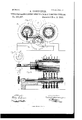
- Figure 1 illustrates a portion of my improvements in a desirable form as applied to a unipolar dynamo maehine, this latter being shown partly in plan and partly in horizontal longitudinal section.
- Fig. 2 illustrates a bar and its conducting-rings detached from an armature of the machine shown in Fig. 1.
- Fi 3 illustrates in section said bar and one of its conducting-rings in working relation with one of my novel brush-conductors, also shown in section.
- Fig. 4 illustrates the conducting disk or brush shown in Fig. 3 in five viewsviz., a side viewand edge view of one of the plates, two inside or coincident face views of the two halves of said brush, and an outside view applicable to either half thereof.
- Fig. 2 illustrates a bar and its conducting-rings detached from an armature of the machine shown in Fig. 1.
- Fi 3 illustrates in section said bar and one of its conducting-rings in working relation with one of my novel brush-conductors, also shown in section.
- FIG. 5 is a view of one end of a machine similar to that shown in Fig. 1, but with a set of the conductingdisk brushes organized so as to be positively rotated.
- Fig. 6 illustrates in section a portion of Fig. 5 011 line .r.
- Fig. 7 is a side view of one of the peculiar laminations or plates detached from a conducting disk or brush of the form shown in Fig. 5.
- Fig. 8, in central vertical section, illustrates another form of dynamo-machine embodying my improvements, in connect-ion with an armature having conducting-rings of another form.
- Fig. 0 is an end view of the machine, Fi 8.
- Fig. 11 in side view illustrates one form of plate detached from the conducting-brush, said plate being like that shown in Fig. 7.
- Figs. 12 and 13 illustrate, respectively, in horizontal and verticallongitudinalsection, the hub or one end of a dynamo'armature of a well-known form and my positively-driven conducting-brushes applied to the opposite sides ofsaid hub.
- Fig. 14 illustrates the same, partially in end v1ew and partially in transverse vertical section.
- Fig. 15 illustrates the same in end view.
- Fig. 16 illustrates in section one of my conducting-disks in a practicable, but less preferred form.
- armatures A and A,each embodying a series of conducting-bars, a, on each of which there are two conducting-rings, b, and that the several conductingbars in one armature are electrically coupled to corresponding bars in the other, so as to form one or more linear series of bars, and also that the said coupling ofthese bars is accomplished by means of intermediate conductors.
- the conductors B are disk-shaped, and are axially mounted upon a shaft, 0, and in similar machines I have heretofore employed disks thus mounted; but said prior disks were substantially solid and flat-faced at their periphcries, and engaged with peripheral rollingcontact with one or two of the fiat-faced con ducting-rings.
- the conductors or brushes B are novel in that they are composed of two separate series of laminations or plates,each substantially of disk form, but so shaped and spirally arranged with re- IIC lation to each other that although said plates are massed side by side a portion ofeach affords a contact'surface for electrically engaging with one side of a conducting-ring flange.
- Fig. 4 at the left-hand portion thereof, one of these plates d is shown in side. view and also in edge view. It has an axial opening atd and a radial slit at d extending from said opening to its periphery; also a circular outline at d extending throughout,say, half its circumference, and an eccentric outline at (1 extending from said radial slit throughout; say, theremaining half ofits circumference.
- These particular conducting-brushes embody two series or sets of said plates,'and their coincident faces are illustrated by the two central portions of Fig. l, while the back of either set or series is illustrated by the right-hand portion of Fig. 4.
- each of the several plates presents a portion of its side, near its periphery, as a contact-surface, available for engaging with a revolving or other surface, with which it is to electrically engage.
- These plates (1 are composed of any good conducting material, and are preferably more or less resilient, so that they will operate with a yielding or spring contact.
- Two sets or series of plates being used, as shown, enables the flange b of a conducting ring to be snugly embraced, and as every one of the plates inboth series serves as a conductor such brushes are not only thoroughly reliable and effective in their operation, but the distribution of wear isso uniform that they are of great durability.
- Fig. 1 for coupling the armature-bars in linear series.
- the lower brushshaft, c is below and parallel with the upper blllSlIShftlli, c, and with the axes of the arniatures A and A.
- any adjacent revolving shaft may be relied upon; but in such machines I prefer to use an armature-shaft, e, and, as here shown, said shaft at its outer end is provided with a thread or worm, e,which meshes with a worm-gear, 9*, on a horizontal shaft, 6, also provided with a thread or worm, e, which meshes with a worm gear, c, on the bruslrshaft c.
- a trough, f is so located that when supplied with mercury the brush will be partially bathed therein, and be enabled to take up between its plates more or less of said lubricant, and also to carry more or less thereof upon its outer surfaces or periphery, and thus not onlyto obviate undue wear atthe contact-points, but also to maintain perfect electrical contacts not only as between the brush and the conducting-ring, but also as between the several plates of the brush.
- Figs. 8 to 11, inclusive wherein I also illustrate means for positively driving said brushes.
- I have illustrated another form of dynamo, but for the purposes of this specification I need only refer to the revolving armature A as one havinga series ot'conductingbars, a, each having conducting-rings b, as before described; but said rings have flat flanges 1), instead of the sharp edged flanges before described.
- the conductors or brushes B here shown are like those last described, but in this case each brush is flatly pressed, near its periphery, against theflat face ofa conductingring flange, b.
- the several brushes are here mounted upon hubs or sleeves g, composed of insulating material, (or said brushes are otherwise insulated from each other,') and said hubs with in certain limit-s can slide longitudinally on the shaft 0, but are revolved therewith.
- Two sets of brushes and two hubs are here shown, and between said hubs there is an expansive spiral spring, on said shaft 0, which causes each of the brushes on each hub to engage under a yielding contact with its respective conducting-ring, thus enabling disk-conductors to be used which have in themselves little or no resiliency, in which case the intervening rings at the hub may be composed of elastic insulating material, and thus provide for a yielding contact of any one disk-conductor independently of others on the same sleeve or hub.
- each brush has its mercurytrough f, and although in this case I also use said troughs as the terminals of certain outside stationary conductors, 1', required in a machine of this type, it is to be understood that the use of said troughs or the mercury therein as such terminals in no manner relates to my presentinvention, the lubricating effect now sought by me being the same, regardless as to what additional use said troughs or their mercury may be applied.
- the shaft 0 of the armature A is the source of power for revolving the brushes.
- a screwthread or worm which meshes with a wormgear, e, on a vertical shaft, 6, having near its lower end a thread or worm, e, which in turn meshes with a large wormgear, e on the brush-shaft c, all substantially as before described.
- Figs. 12 to 15, inclusive wherein I show the hub of a revolving armature common to such machines as involve the use of a commutatoras, for instance, the Gramme or the Siemens machines. As here shown, the
- my novel brushes be constructed as shown in Figs. 4 or 7, and make specific claim to such as are composed of a' series of plates or lam'inations so formed and arranged with relation to each other that each plate affords a side contactsurface, near its periphery, I do not limit myself thereto, it being, as I believe, broadly new to construct an electric annular or disk-shaped brush composed of a series of plates or laminations, all of which can engage at or near their peripheries in electric contact with a moving surface in a plane at right angles to the axis of said disk. This result is not dependent upon the peculiar cuts or forms illustrated in Figs.
- each brush composed of a series of laminations or plates, each formed and the whole arranged with relation to each other, as illustrated in Fig. 16, Sheet 1, of the drawings.
- this form of brush there is a series of laminations or plates, (2, all having an axial opening, and each is concave-convex adjacent to its periphery.
- each succeding plate islarger in diam eter than the preceding plate, and the edges of all of said plates occupy substantially the same plane, so that when the brush is in service each plate has its own specific point or points of contact.
- This form of brush is, like the others, well adapted to carry mercury as a lubricant, and possesses the desired resiliency and operates with a peculiar frictional contact which renders it highly effective.
- a brush is composed of a single series of theconcavo-convex laminations or plates, as shown, it is well adapted for use in the manner illustrated in Figs. 8 and 12; but two of such series of plates should be employed in a brush ifit is to be employed with sharp edged flanges or double contact-surfaces, as shown in Figs. 1 and 6.
- a disk-shaped electricbrush conductor composed of a series of laminations or plates, each affording at or near its periphery a surface for electric contact in a plane substantially at right angles to the axis of said disk.
- a disk-shaped electric-brush conductor composed of two series of laminations or plates, each plate affording at or near its periphery a surface for electric contact ina plane substantially at right angles to the axis of said disk, and having the contact-surfaces of the two series of plates coincident with each other, substantially as described, whereby a conductor with which said brush is to operate can be embraced between said two series of plates at or near their peripheries.
- a disk-shaped electric-brush conductor composed of laminations or plates having an axial opening, a radial slit, and a portion thereof cut away on eccentric lines, substantially as described.
Landscapes
- Engineering & Computer Science (AREA)
- Power Engineering (AREA)
- Motor Or Generator Current Collectors (AREA)
Description
I (No Model.) I 4 Sheets-Sheet 1.
- R. EIOKEMEYER.
DEVICE FOR TAKING ELECTRIC OURRENTS FROM OR TO MOVING SURFACES,
No. 351,907. Patented Nov. 2, 1886.
In?) evvor: Rud oyl ioke ng n (No Model.) 4 Sheets-Sheet 2.
R. EIGKEMEYER. DEVICE FOR TAKING ELBGTRIO GURRENTS FROM OR TO MOVING SURFACES. No. 351,907. Patented Nov. 2, 1886.
% RudO Z/Ewkemeyen (No Model.) 4 Sheets-Sheet 3. R. .BICKEMEYER.
DEVICE FOR TAKING ELECTRIC G URRENT S FROM OR TO MOVING SURFACES. No. 351,907. Patented Nov. 2, 1886.
67566 2?: i572) enzor icicem yer,
v State of New York, have invented certain new UNITED STATES PATENT OFFICE RUDOLF EIOKEMEYER, OF YONKEBS, NEW YORK.
DEVICE FOR TAKING ELECTRIC CURRENTS FROM OR TO MOVING SURFACES.
SPECIFICATION forming part of Letters Patent No. 351,907 dated November 2, 1886.
Application filed December 3, 1885. Serial No. 184,545. (No model.)
To. all whom it may concern.-
Be it known that I, RUDOLF Eicnmunvnn, of Yonkers, in the county of W'cstchcster and and useful Improvements in Devices for Taking Electric Currents from or Conveying them to Revolving or Moving Surfaces; and I do hereby declare that the following specification,
taken in connection with the drawings fur nished, and forming a part of the same, is a clear, true, and complete description of the several features of my invention.
Devices for the purpose stated have heretofore been usually designated by the general term, brushes, regardless of their specific construction. As a rule, such brushes have been masses of wire arranged like thebristles of an ordinary brush; but in some cases fiat plates or springs have been employed, both sin '1 and in rou )s and in other cases rollers backed by springs have been employed for angles to the axis of the brush.
The main object of my invention is to obtain a reliable and durable electrical contact with a minimum resistance, and in that connection I have for the first time, as I believe, devised for use with the revolving device, from or to which an electric current is to be taken or applied, a brush or its equivalent of any kind which is rotated positively, as distinguished from being rotated by reason of its mere frictional contact with anotherv revolving surface .with which it electrically engages. ,For obtaining the best results, said brush or its equivalent should be thus positively rotated at a speed much less thanthe revolving surthe brush or its equivalent should be revolved I face with which it engages, although, should this latter be revolved at specially low speed,
ticular feature of my invention is obviously not dependent upon any particularconstruction of the brush or its equivalent; but for obtaining an extraordinary degree of efficiency and durability I" have devised a disk-shaped eonductor, (which may be properly termed a brush,) which is broadly new,'in that it is disk-shaped and composed of a series of laminations or plates placed side by side and clamped together, so that each can engage, under yielding pressure, with any surface with which the disk maybe used as an electric conductor, and the contactsurfaces of these disks and the several plates are presented in a plane at right angles to the axis of the brush, or at least in a plane which is not parallel with said axis, as distinguished from ordinary rollercontacts which have contact-surfaces parallel with their axes, and also as distinguished from certain solid roller-contacts heretofore used by me, having eitherwedge-shaped or inclined grooved peripheries.
In their best form, the plates of which my novel brushes are composed are peculiarly out, so that when placed side by side and spirally arranged, each of the plates in any one series will present a portion of its side, near its periphery,in a plane'substantially common to all of the plates in said series, and hence as the disk is revolvethfiatly pressing its side, near its periphery against any smooth surface,each disk will have its individual contact-point during its proportion of the rotation of said disk. In another form said plates are of successively greater diameter, and near its periphery each plate is annularly concaveeonvex, so that the edge of each will occupya plane common to all, and hence each will press edgewise against any surface with which'the disk may be placed in lateral contact at that portion of its periphery occupied by the edges of said plate.
Electric-brush conductors embodyinginyinvention differ radically from all roller contacts heretofore known. Said roller-contacts operate only with peripheral engagement, and hence the surface area of contact is so slight as to involve high resistance, and the least oxidation of said surfaces results in varied conductivity. My brushesoperate without peripheral engagement, but with a broad plane surface, and with such an'extensive area of contact that resistance is reduced to a minimum, and any ordinary spots of oxidation fail to impair their efficiency. My brush conductors also radically differ from the ordinary flat-wire brushes and flat-plate brushes, in that these maintain fixed relations at their contact-points, while mine, being in disk form and rotativcly mounted, can be frequently or continuously varied with relation to their contact-points, not only without dcranging their conductive capacities, but in fact improving them.
For securing a reliable electric contact as between the several plates in each disk or in each series of plates, and also for lubricating their contact-points, I employ a mercurybath in which a portion of each disk is always immersed.
I am aware of the varied use of mercury as an intermediate conductor, as between moving and stationary conductors, and it is to be distinctly understood that I make no claim thereto other than as a lubricating medium, and in combination with a positively-driven brush, and especially in combination with a brush composed of a series of laminations or plates clamped together, so that each of said plates can separately afford a yielding contactsurfacc.
The prime value of my present improvements accrues in connection with their use in electric generators or electric motors, and although I have illustrated said improvements in connection with certain dynamoelectric machines heretofore devised by me, and also in connection with other forms of well-known dynamo-electric machines, it is to be understood that my present application is to be in no manner limited to machines of any particular kind, or to such as are organized for any special purpose.
After describing the several illustrations of my present improvements, which are presented in the accompanying drawings, the novel features to be embraced in this application will be specified in the several clauses of claims hereunto annexed.
Figure 1 illustrates a portion of my improvements in a desirable form as applied to a unipolar dynamo maehine, this latter being shown partly in plan and partly in horizontal longitudinal section. Fig. 2 illustrates a bar and its conducting-rings detached from an armature of the machine shown in Fig. 1. Fi 3 illustrates in section said bar and one of its conducting-rings in working relation with one of my novel brush-conductors, also shown in section. Fig. 4 illustrates the conducting disk or brush shown in Fig. 3 in five viewsviz., a side viewand edge view of one of the plates, two inside or coincident face views of the two halves of said brush, and an outside view applicable to either half thereof. Fig. 5 is a view of one end of a machine similar to that shown in Fig. 1, but with a set of the conductingdisk brushes organized so as to be positively rotated. Fig. 6 illustrates in section a portion of Fig. 5 011 line .r. Fig. 7 is a side view of one of the peculiar laminations or plates detached from a conducting disk or brush of the form shown in Fig. 5. Fig. 8, in central vertical section, illustrates another form of dynamo-machine embodying my improvements, in connect-ion with an armature having conducting-rings of another form. Fig. 0 is an end view of the machine, Fi 8. Fig. lOillustrates an armature-bar, its ring, and my novel conductingbrush, in side view, detached from the machine. Fig. 11 in side view illustrates one form of plate detached from the conducting-brush, said plate being like that shown in Fig. 7. Figs. 12 and 13 illustrate, respectively, in horizontal and verticallongitudinalsection, the hub or one end of a dynamo'armature of a well-known form and my positively-driven conducting-brushes applied to the opposite sides ofsaid hub. Fig. 14 illustrates the same, partially in end v1ew and partially in transverse vertical section. Fig. 15 illustrates the same in end view. Fig. 16 illustrates in section one of my conducting-disks in a practicable, but less preferred form.
Referring to Fig. 1, it need only be understood, for the purposes of this specification, that the machine thereby partially illustrated is of the unipolar variety, and contains two revolving armatures, A and A,each embodying a series of conducting-bars, a, on each of which there are two conducting-rings, b, and that the several conductingbars in one armature are electrically coupled to corresponding bars in the other, so as to form one or more linear series of bars, and also that the said coupling ofthese bars is accomplished by means of intermediate conductors.
The only features which directly relate to my present improvements are the intermediate conductors,l3, here used with conducting-rings b of a novel form. In somewhat similar machineslhave heretofore employed conductingrings having flat peripheries, and the novel feature now disclosed in that connection is a peripheral flange, b, on said rings, whereby a more extended contact-surface is afforded for each ring than when a fiangeless ring is employed. The flange Z) may be so organized with auintermediate conductor that but one side of said flange will serve as a contact; but, as shown in Figs. 1, 2, and 3, said flange is angular or wedge-shaped, and both of its sides serve as contact-surfaces. The conductors B, as here shown, are disk-shaped, and are axially mounted upon a shaft, 0, and in similar machines I have heretofore employed disks thus mounted; but said prior disks were substantially solid and flat-faced at their periphcries, and engaged with peripheral rollingcontact with one or two of the fiat-faced con ducting-rings. The conductors or brushes B, as here shown, are novel in that they are composed of two separate series of laminations or plates,each substantially of disk form, but so shaped and spirally arranged with re- IIC lation to each other that although said plates are massed side by side a portion ofeach affords a contact'surface for electrically engaging with one side of a conducting-ring flange.
In Fig. 4:, at the left-hand portion thereof, one of these plates d is shown in side. view and also in edge view. It has an axial opening atd and a radial slit at d extending from said opening to its periphery; also a circular outline at d extending throughout,say, half its circumference, and an eccentric outline at (1 extending from said radial slit throughout; say, theremaining half ofits circumference. These particular conducting-brushes embody two series or sets of said plates,'and their coincident faces are illustrated by the two central portions of Fig. l, while the back of either set or series is illustrated by the right-hand portion of Fig. 4.
From these figures and the description thus far given it will be readily understood that each of the several plates presents a portion of its side, near its periphery, as a contact-surface, available for engaging with a revolving or other surface, with which it is to electrically engage. These plates (1 are composed of any good conducting material, and are preferably more or less resilient, so that they will operate with a yielding or spring contact. Two sets or series of plates being used, as shown, enables the flange b of a conducting ring to be snugly embraced, and as every one of the plates inboth series serves as a conductor such brushes are not only thoroughly reliable and effective in their operation, but the distribution of wear isso uniform that they are of great durability. It is to be understood that I do not limit myself to this particular cut or form of plate or lamination, it being broadly new, as I believe, to combine in an electric-brush conductor a series of plates or laminatious, however cut or formed, in which all the plates have their separate orindividual contact with the moving surface with which said plates are operated as electric conductors.
For illustrating a practicable variation in the cut and form of the laminations or plates, I will refer to Fig. 7, in which the plate d is circular in its outline, instead of eccentric,
but ithas the radial slit (1 and axial opening (2, before described. a portion of its interior cut away on eccentric lines, extending from said radial slit, so that when a series or set of these plates are placed side by side and spirally arranged and clamped on their shaft 0, each plate presents a portion of its side, near its periphery,asa contact-surface, which can either be pressed flatly against This plate has, however,-
Fig. 1,) for coupling the armature-bars in linear series. The lower brushshaft, c, is below and parallel with the upper blllSlIShftlli, c, and with the axes of the arniatures A and A.
I will next describe how the several conductors or brushes B are positively driven or revolved, and this I deem a broadly novel feature, regardless of the character of the machine in which said brushes are or may be used, and also regardless of any particular form or construction of the brush itself. As a source of power for revolving said brushes and their shaft, any adjacent revolving shaft may be relied upon; but in such machines I prefer to use an armature-shaft, e, and, as here shown, said shaft at its outer end is provided with a thread or worm, e,which meshes with a worm-gear, 9*, on a horizontal shaft, 6, also provided with a thread or worm, e, which meshes with a worm gear, c, on the bruslrshaft c. If the conducting-rings herevolved at high speed,it is desirable that the brushes be revolved at a much slower speed, whether said brushes and rings be revolved in the same or in opposite directions. It will be seen that if the several plates in each brush are lubricated their durability will be greatly enhanced, and also that if a lubricant be used which is a good electric conductor greater efficiency will accrue, and hence I employ mercury as a lubricant. Below each brush a trough, f, is so located that when supplied with mercury the brush will be partially bathed therein, and be enabled to take up between its plates more or less of said lubricant, and also to carry more or less thereof upon its outer surfaces or periphery, and thus not onlyto obviate undue wear atthe contact-points, but also to maintain perfect electrical contacts not only as between the brush and the conducting-ring, but also as between the several plates of the brush.
As hereinhefore stated, I am aware of the extensive and varied use of mercury in electrical apparatus, and have myself employed it heretofore in connection with rolling or moving contacts in machines devised by me; but I know of no priorinstancein which mercury has been employed as a lubricant for a revolving brush composed of laminations" or plates, nor any prior instance wherein a mercury-bath has been employed with a revolving brush or revolving conductor of any kind positively. driven, and thereby so controlled as to prevent the mercury from being undul y displaced, as is the case with a brush revolving at a high speed in contact with mercury.
I will next refer to Figs. 8 to 11, inclusive, wherein I also illustrate means for positively driving said brushes. In said Figs. 8 and 9 I have illustrated another form of dynamo, but for the purposes of this specification I need only refer to the revolving armature A as one havinga series ot'conductingbars, a, each having conducting-rings b, as before described; but said rings have flat flanges 1), instead of the sharp edged flanges before described. The conductors or brushes B here shown are like those last described, but in this case each brush is flatly pressed, near its periphery, against theflat face ofa conductingring flange, b. The several brushes are here mounted upon hubs or sleeves g, composed of insulating material, (or said brushes are otherwise insulated from each other,') and said hubs with in certain limit-s can slide longitudinally on the shaft 0, but are revolved therewith. Two sets of brushes and two hubs are here shown, and between said hubs there is an expansive spiral spring, on said shaft 0, which causes each of the brushes on each hub to engage under a yielding contact with its respective conducting-ring, thus enabling disk-conductors to be used which have in themselves little or no resiliency, in which case the intervening rings at the hub may be composed of elastic insulating material, and thus provide for a yielding contact of any one disk-conductor independently of others on the same sleeve or hub. In this machine each brush has its mercurytrough f, and although in this case I also use said troughs as the terminals of certain outside stationary conductors, 1', required in a machine of this type, it is to be understood that the use of said troughs or the mercury therein as such terminals in no manner relates to my presentinvention, the lubricating effect now sought by me being the same, regardless as to what additional use said troughs or their mercury may be applied. As shown in said Figs. 8 and 9, the shaft 0 of the armature A is the source of power for revolving the brushes. At the outer end of the shaftc there is a screwthread or worm, c, which meshes with a wormgear, e, on a vertical shaft, 6, having near its lower end a thread or worm, e, which in turn meshes with a large wormgear, e on the brush-shaft c, all substantially as before described. I
For further illustrating the varied utility of the main features of my invention, I will refer to Figs. 12 to 15, inclusive, wherein I show the hub of a revolving armature common to such machines as involve the use of a commutatoras, for instance, the Gramme or the Siemens machines. As here shown, the
- several armature-conductors terminate at the brush is positively driven by means of its own Worm-gear c and its worm and worm-shaft 6'; but both of these latter are driven by means In this case each.
of corded belts running in grooves 011 the armature shaft and engaging with large grooved pulleys on said worm-shaft 0 Each of these brushes has its lubricating mercury bath or trough f, and these latter also serve as the electric terminals of the machine. In machines of this type thcadvantages accruing from the use of a. positively-driven brush, with or without its mercury-bath, are not dependent upon a brush of any special form, it being obvious that if the conducting disk or brush be composed of practically non-resilient materiala disk of carbon, for instancc-it could be made to engage with yielding contact by the use of a spring at its hub, as already described.
While I prefer that my novel brushes be constructed as shown in Figs. 4 or 7, and make specific claim to such as are composed of a' series of plates or lam'inations so formed and arranged with relation to each other that each plate affords a side contactsurface, near its periphery, I do not limit myself thereto, it being, as I believe, broadly new to construct an electric annular or disk-shaped brush composed of a series of plates or laminations, all of which can engage at or near their peripheries in electric contact with a moving surface in a plane at right angles to the axis of said disk. This result is not dependent upon the peculiar cuts or forms illustrated in Figs. 4 and 7, but can be produced with a brush composed of a series of laminations or plates, each formed and the whole arranged with relation to each other, as illustrated in Fig. 16, Sheet 1, of the drawings. In this form of brush, there is a series of laminations or plates, (2, all having an axial opening, and each is concave-convex adjacent to its periphery. Commencing from an outer plate on one side of the brush, each succeding plate islarger in diam eter than the preceding plate, and the edges of all of said plates occupy substantially the same plane, so that when the brush is in service each plate has its own specific point or points of contact. This form of brush is, like the others, well adapted to carry mercury as a lubricant, and possesses the desired resiliency and operates with a peculiar frictional contact which renders it highly effective. When a brush is composed of a single series of theconcavo-convex laminations or plates, as shown, it is well adapted for use in the manner illustrated in Figs. 8 and 12; but two of such series of plates should be employed in a brush ifit is to be employed with sharp edged flanges or double contact-surfaces, as shown in Figs. 1 and 6.
It will be readily seen that if the brush in the form illustrated in Fig; 16 should have all of its plates radially slotted at frequent intervals its resiliency would be greatly increased and render it as sensitive in that respect as the other forms of brush previously described, and that this construction would resemble and be in substance a mass of flat wires au- IIO nularly arranged in disk form, and, inasmuch as the end of each wire or arm in each plate would afford the contact-surface, said wires or arms could be composed of round wire without materially affecting the results. So also will it be seen that the plates shown in Fig. 4 might also be radially slitted at frequent intervals without materially impairing their value, the main point to be observed being that the brush be in the form of adisk and adapted to afford lateral contact as distinguished from peripheral contact.
While my novel brushes are of special value for use in connection with revolving contactsurfaces because of the low resistance secured by the extensive areas of contact and the considerable conductive capacity of each plate, as well as the massing of all the plates in close electric contact, it will be obvious that they will be equally effective and useful if used in connection with contact-surfaces which reciprocate, and even with such as are stationaryas, for instance, either form of the novel brush shown will operate effectively in connection with a flat-faced stationary conducting-bar.
The rotativecapacity of a brush composed of laminatious or plates according to my invention I deem of value, even if said brushes be not positively driven-as, for instance, if in the machine shown in Fig. 8, the brushshaft were uncoupled from the armature-shaft the several brushes could at proper intervals be partially rotated, and thus present fresh surfaces for contact, and more or less of the lubricant would be carried by the brush.
Having thus described my invention, I claim as new and desire to secure by Letters Patent- 1. The combination, substantially as herei nbefore described, of one or more disk-shaped electric conductors, a rotative shaft on which said conductors are mounted, and gearing by which said shaft and the brush-conductors are positively rotated.
2. The combination, substantially as hereinbefore described, of one or more disk-shaped electric conductors, a rotative shaft on which said conductors are mounted, gearing by which said shaft is positively driven, and a mercury bath for lubricating each conductor.
3. A disk-shaped electricbrush conductor composed of a series of laminations or plates, each affording at or near its periphery a surface for electric contact in a plane substantially at right angles to the axis of said disk.
at. A disk-shaped electric-brush conductor composed of two series of laminations or plates, each plate affording at or near its periphery a surface for electric contact ina plane substantially at right angles to the axis of said disk, and having the contact-surfaces of the two series of plates coincident with each other, substantially as described, whereby a conductor with which said brush is to operate can be embraced between said two series of plates at or near their peripheries.
5. A disk-shaped electric-brush conductor composed of laminations or plates having an axial opening, a radial slit, and a portion thereof cut away on eccentric lines, substantially as described.
6. The combination, with a disk shaped brush-conductor composed of laminations or plates and axially mounted, of a mercurybath for lubricating said plates, substantially as described.
7. The combination, substantially as hereinbefore described, of arotative shaft and one or more electric brushes mounted thereon, each composed of a series of laminations or plates massed together and affording a contact-surface in a plane substantially at right angles to the axis of the brush, whereby many or all of said plates may be successively engaged in lateral contact with a cooperating electric conductor.
RUDOLF EICKEMEYER.
Witnesses:
HENRY OsTERHELD, .TAMEs S. FITCH.
Publications (1)
| Publication Number | Publication Date |
|---|---|
| US351907A true US351907A (en) | 1886-11-02 |
Family
ID=2420966
Family Applications (1)
| Application Number | Title | Priority Date | Filing Date |
|---|---|---|---|
| US351907D Expired - Lifetime US351907A (en) | eickemeyer |
Country Status (1)
| Country | Link |
|---|---|
| US (1) | US351907A (en) |
Cited By (3)
| Publication number | Priority date | Publication date | Assignee | Title |
|---|---|---|---|---|
| US3619681A (en) * | 1970-06-01 | 1971-11-09 | Frank Ginkel | Rotary seal and rotary electrical coupling embodying same |
| US20060279164A1 (en) * | 2005-06-08 | 2006-12-14 | Dynamo Capital, Inc. | Superconducting Acyclic Homopolar Electromechanical Power Converter |
| US20100264771A1 (en) * | 2009-04-15 | 2010-10-21 | Dynamo Capital, Inc. | Internal Impedance Converting Superconducting Acyclic Power Converter |
-
0
- US US351907D patent/US351907A/en not_active Expired - Lifetime
Cited By (5)
| Publication number | Priority date | Publication date | Assignee | Title |
|---|---|---|---|---|
| US3619681A (en) * | 1970-06-01 | 1971-11-09 | Frank Ginkel | Rotary seal and rotary electrical coupling embodying same |
| US20060279164A1 (en) * | 2005-06-08 | 2006-12-14 | Dynamo Capital, Inc. | Superconducting Acyclic Homopolar Electromechanical Power Converter |
| US7463914B2 (en) | 2005-06-08 | 2008-12-09 | Dynamo Capital, Inc. | Superconducting acyclic homopolar electromechanical power converter |
| US20100264771A1 (en) * | 2009-04-15 | 2010-10-21 | Dynamo Capital, Inc. | Internal Impedance Converting Superconducting Acyclic Power Converter |
| US8078242B2 (en) | 2009-04-15 | 2011-12-13 | Dynamo Capital, Inc. | Internal impedance converting superconducting acyclic power converter |
Similar Documents
| Publication | Publication Date | Title |
|---|---|---|
| US2345835A (en) | Device for collecting electric current | |
| JPS604661B2 (en) | sliding electrical contact members | |
| US2520709A (en) | Control switch | |
| US351907A (en) | eickemeyer | |
| US2457178A (en) | Resistance sine wave generator | |
| US4086509A (en) | Sandwiched slip ring assembly | |
| US428454A (en) | Electric motor | |
| US345336A (en) | Commutator-brush | |
| US1216413A (en) | Current-converting device. | |
| US1306923A (en) | Electric-current-changing means | |
| US1143175A (en) | Synchronous electrical contact-maker. | |
| US423912A (en) | Com m utato r-bru sh | |
| US339772A (en) | heeina | |
| US399329A (en) | Best available cop | |
| US252405A (en) | House | |
| US805315A (en) | Unipolar machine. | |
| US550703A (en) | Fourths to charles d | |
| US351904A (en) | Budolf eickemeyee | |
| US678157A (en) | Dynamo-electric machine. | |
| US1098557A (en) | Rotary converter. | |
| US350728A (en) | Electric motor or generator | |
| US1243286A (en) | Slip-ring for dynamo-electric machines. | |
| US342589A (en) | Dynamo-electric machine | |
| US728256A (en) | Brush for dynamo-electric machines. | |
| JP2022114122A (en) | Power supply device |