US3484107A - Multiple alley bowling game scoring system including lane sequencer - Google Patents
Multiple alley bowling game scoring system including lane sequencer Download PDFInfo
- Publication number
- US3484107A US3484107A US498456A US3484107DA US3484107A US 3484107 A US3484107 A US 3484107A US 498456 A US498456 A US 498456A US 3484107D A US3484107D A US 3484107DA US 3484107 A US3484107 A US 3484107A
- Authority
- US
- United States
- Prior art keywords
- lane
- pinfall
- bowling
- information
- lanes
- Prior art date
- Legal status (The legal status is an assumption and is not a legal conclusion. Google has not performed a legal analysis and makes no representation as to the accuracy of the status listed.)
- Expired - Lifetime
Links
- 230000015654 memory Effects 0.000 description 20
- 230000000903 blocking effect Effects 0.000 description 14
- 238000001514 detection method Methods 0.000 description 13
- 230000033001 locomotion Effects 0.000 description 6
- 238000005096 rolling process Methods 0.000 description 6
- 230000011664 signaling Effects 0.000 description 6
- 230000001186 cumulative effect Effects 0.000 description 4
- 238000000034 method Methods 0.000 description 4
- 230000000994 depressogenic effect Effects 0.000 description 3
- 238000010586 diagram Methods 0.000 description 3
- 238000009434 installation Methods 0.000 description 3
- 230000004048 modification Effects 0.000 description 3
- 238000012986 modification Methods 0.000 description 3
- 101000898093 Homo sapiens Protein C-ets-2 Proteins 0.000 description 2
- 102100021890 Protein C-ets-2 Human genes 0.000 description 2
- 101100355601 Saccharomyces cerevisiae (strain ATCC 204508 / S288c) RAD53 gene Proteins 0.000 description 2
- 230000001351 cycling effect Effects 0.000 description 2
- 230000000694 effects Effects 0.000 description 2
- 230000006870 function Effects 0.000 description 2
- 230000004044 response Effects 0.000 description 2
- 108010054404 Adenylyl-sulfate kinase Proteins 0.000 description 1
- 101100065718 Caenorhabditis elegans ets-4 gene Proteins 0.000 description 1
- 101100298998 Caenorhabditis elegans pbs-3 gene Proteins 0.000 description 1
- 101150012532 NANOG gene Proteins 0.000 description 1
- 241000276498 Pollachius virens Species 0.000 description 1
- 101100396520 Saccharomyces cerevisiae (strain ATCC 204508 / S288c) TIF3 gene Proteins 0.000 description 1
- 102100039024 Sphingosine kinase 1 Human genes 0.000 description 1
- 230000004913 activation Effects 0.000 description 1
- 230000005540 biological transmission Effects 0.000 description 1
- 101150084500 cel2 gene Proteins 0.000 description 1
- 230000001934 delay Effects 0.000 description 1
- 239000002783 friction material Substances 0.000 description 1
- 238000012163 sequencing technique Methods 0.000 description 1
- 125000006850 spacer group Chemical group 0.000 description 1
- 101150038107 stm1 gene Proteins 0.000 description 1
Images


Classifications
-
- A—HUMAN NECESSITIES
- A63—SPORTS; GAMES; AMUSEMENTS
- A63D—BOWLING GAMES, e.g. SKITTLES, BOCCE OR BOWLS; INSTALLATIONS THEREFOR; BAGATELLE OR SIMILAR GAMES; BILLIARDS
- A63D5/00—Accessories for bowling-alleys or table alleys
- A63D5/04—Indicating devices
-
- A—HUMAN NECESSITIES
- A63—SPORTS; GAMES; AMUSEMENTS
- A63D—BOWLING GAMES, e.g. SKITTLES, BOCCE OR BOWLS; INSTALLATIONS THEREFOR; BAGATELLE OR SIMILAR GAMES; BILLIARDS
- A63D5/00—Accessories for bowling-alleys or table alleys
- A63D5/04—Indicating devices
- A63D2005/048—Score sheets
Definitions
- a bowling scoring system for computing the bowling scores achieved by a plurality of bowlers bowling on a plurality of lanes including a plurality of pin detecting systems, one for each lane, a single computation unit for receiving pinfall information from any one of the pin detecting systems and a scanning unit interposed between the single computation unit and the plurality of pinfall detecting systems for continuously scanning the pinfall detecting systems to determine when pinfall information has been detected thereby and for connecting a given one of the pinfall detecting systems to the single computation unit when pinfall information is available thereat.
- Another object is to provide such a scoring system in which a scanning device is used to scan lanes to search for a lane with pinfall information ready and to control a computation unit to receive pinfall information from the lane after the lane has been found.
- Still another object of this invention is to provide a scoring system in accordance with any of the foregoing objects, which system is capable of directing entry of corrected score and is capable of directing the handling of corrected score information by the computation unit.
- Another object is to provide for correction of erroneous score on one of a plurality of lanes without tying up the information entry channels of any one lane for an unduly long time.
- Yet another object of this invention is to provide a new and useful lane selection system for use in the scoring system in any of the foregoing objects.
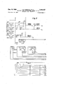
- FIG. 1 is a diagrammatic showing of a scoring system for scoring consecutive bowling games bowled on a plurality of bowling lanes;
- FIG. 2 is a section through a form of scanning device useful in the system of FIG. 1;
- FIG. 3 is a perspective view of a clutch plate and cam member in the device of FIG. 2;
- FIG. 4 is a view taken along line 44 in FIG. 2;
- FIG. 5 is a section taken along line 55 in FIG. 2;
- FIGS. 6-9 are wiring diagrams illustrating a control system for the scoring system of FIG. 1.
- the scoring system of this invention is useful, in conjunction with a bowling installation having a plurality of lanes, for concurrently scoring a multiplicity of generally concurrent games played by a multiplicity of players on the plurality of lanes.
- the bowlers may bowl as individuals or as members of a team.
- pinfall information e.g., from pinfall detection means which may be installed at the pin setup end of the lane such as in an automatic pinsetter, is received by a totalizer and is converted to a pinfall count or total which is used by a computation unit in computing bowling scores.
- the identity of the bowler to whom a given computed score is attributed is coordinated with the pinfall information to assure correct awarding of the score to the player earning the score.
- a single selection system common to a plurality of bowling lanes, is provided for selecting one lane at a time and for controlling the acceptance of pinfall information from the selected lane for computation purposes.
- the lane selection system is also capable of controlling the entry of corrected score for purposes of correcting any errors in score which may have been entered during operation of the scoring system.
- FIG. 1 there is illustrated a bowling installation adapted for use in accordance herewith.
- four bowling lanes lanes L1, L2, L3 and L4, i.e. two lane pairs L1 and 2 and L3 and 4, are illustrated, it is to be understood that the present system is useful or can be readily adapted for use with any plurality of bowling lanes and especially with any plurality of lane pairs.
- Each of lanes L1 through L4 is provided in the usual manner with a divider 12 therebetween and each lane includes an automatic pinsetter, indicated generally at AP1, AP2, AP3, and AP4, at the pin setup end of the lane.
- Balls are bowled in the usual manner and returned through a conventional common ball return system for each lane pair having a bal outlet 13 for delivery of balls to a ball pick-up station, shown as a ball storage rack 14, from which the balls may be removed for bowling.
- a bowlers identification console 15 is provided for each lane pair for use by bowlers to manually feed bowler identification and lane information to the scoring system.
- a structure in the form of a housing 18 encloses and supports components of the scoring system.
- the present system can be expanded to accommodate a greater plurality of lanes, by duplicating components, the present system employs the same basic pinsetter modifications and a computation system as disclosed by Georgia et al., but also expands the two lane system more conveniently for operation with greater than two lanes.
- the pin detection system and over-all computation and control system of Cornell et al. is useful in accordance with the present invention; and, for purposes of clearer understanding of the present invention, reference will be. made to various components in the Cornell et al. application during the description of the present invention.
- each of automatic pinsetters AP1 through AP4 (FIG. 1) is provided with a' signal generating means in the form of a switch AP90 (FIG. 8), i.e.
- each pinfallready signal is made available to a lane selector21, as indicated by control lines PR1 through PR4, and the lane selector 21 scans the lanes sequentially until a pinfallready signal is detected or found.
- the lane selector 21 directs the pinfall information from the appropriate automatic pinsetter AP1 through AP4 to the computation and control system indicated at 22, via line PP.
- the pinfall information is received in a summation section where it is converted to a pin count.
- the pin count is then used by the computer and control section to compute bowling scores and enter the bowling scores into the proper bowler memories, designated BM, for the bowler to whom the score is to be attributed.
- Bowler identification information is received from the bowler identification panels 15 by the computer and control section.
- an error correction console or panel 23 at housing 18, which services four lanes and is useful for causing the computation unit to erase erroneous stored score from a particular bowler memory and for introducing corrected score information.
- The'over-all operation of the scoring system will be described in more detail hereinbelow, after description re lating to the lane selector device.
- the lane selector 21 is in the form of a scanning device which is best understood with reference to FIGS, 2-5.
- the drive portion of the scanning device includes a torque responsive clutch 33 having an input pulley 31, which can be driven through a drive chain (not shown) from a suitable motor (not shown), and an output shaft 32 which drives a scanner clockwise as viewed in FIG. 4.
- the torque responsive clutch permits relative movement of its clutch faces without undue wear under heavy load conditions imposed by the scanner, e.g. when the scanner is suddenly stopped while driving of pulley 31 is continued.
- the torque responsive clutch 33 includes a frame 34 through which shaft 32 is rotatably supported by bearings 35; shaft 32 is restrained against axial movement by rings 35a.
- a sleeve 36 concentric with shaft 32, surrounds a portion of shaft 32 and is spaced and supported. from shaft 32 by bearings 37 so that sleeve 36 can be rotated relative to shaft 32.
- Sleeve 36 is pinned to input pulley 31 for rotation therewith.
- Mounted on sleeve 36 forrotation therewith are a wheel 41 and a pair of ball bearing rollers 42, with rollers 42 having their axes projecting outward from sleeve 36 so that rollers 42 rotate about an axis transverse to the axis of sleeve 36 and shaft 32.
- a clutch plate 43 having a pair of integral cam ridges 44 (best seen in FIG. 3) and a central bore with a bushing of friction material 45 within the bore, is slidable on sleeve 36 to permit relative rotation between sleeve 36 and clutch plate 43.
- Clutch plate '43 carries a clutch face 46 for engaging a clutch plate 47 which is pinned to shaft 32 for rotation therewith.
- a torsion coil spring 48 is secured in bores 49 and 50 at opposite ends by set screws 51 and 52 to clutch plate 43 and wheel 41 and biases between clutch plate 43 and wheel 41 so that as Wheel 41 rotates, clutch plate 43 is driven thereby through torsion spring 48.
- the cam ridges 44 are of proper arcuate length and height to maintain engagement with the rollers 42 at a position intermediate the ends of the cam ridges while the clutch face 46 is in driving engagement with clutch plate 47 and with torsion Spring 48 under insufficient torsion to overcome the spring.
- pulley 31 In operation of the clutch device, pulley 31 is driven in the same rotational direction as output shaft 32 to rotate sleeve 36, wheel 41 and rollers 42 about the axis of shaft 32. Wheel 41 also drives clutch plate 43 through torsion spring 48 to thereby drive output shaft 32 through clutch plate 47.
- Spring 48 is under torsion and rollers 22 are in an intermediate position on the inclines of cam ridges 44 to hold clutch face 46 in tight engagement with clutch plate 47.
- the torque on output shaft 32 is transmitted through clutch plates 47 and 43 to torsion spring 48. Should the torque increase sufiicient to overcome spring 48, wheel 41 rotates in the direction driven relative to clutch plate 43.
- rollers 42 roll down the incline of the cam ridge 44 until clutch face 46 is permitted to slip on clutch plate 47, so that the clutch is, in effect, disengaged from driving shaft 32.
- torsion spring 48 is enabled to drive clutch plate 43 in the direction of rotation of wheel 41 as rollers 42 proceed up the ramp of cam ridge 44 so that clutch face 46 is again tightly held against clutch plate 47 and the clutch is reengaged.
- a sleeve 55 is pinned to shaft 32 for rotation therewith, and a first circular outer cam plate 56 is secured to sleeve 55.
- Cam plate 56 carries pins 57, to which a second outer cam plate 58 is secured, spaced from cam plate 56.
- Bearings 61 on shaft 32 support another sleeve 62, spaced from shaft 32.
- Mounted on sleeve 62, for rotation therewith, are first and second inner cam plates 64 and 65 and a carrier plate 63 (FIGS. 2 and 4) having a crank lever 66 mounted thereon by suitable means, shown at 67, for pivoting about a pivot pin 68.
- Pins 57 impale inner cam plates 64 and 65 through slots 71.
- Each of slots 71 is of an arcuate length permitting limited relative rotary movement between the inner cam plates 64, 65 and the outer cam plates 56, 58.
- a tension spring 72 is mounted at opposite ends by pins 73 and 74 respectively to cam plates 56 and 64, normally maintaining the inner cam plates 64 and 65 rotating in a leading angular disposition relative to the outer cam plates 56 and 58 and with pins 57 disposed at the trailing ends of slots 71.
- a slot 75 is provided in cam plate 56 so that pin 74 does not block the relative rotary movement of cam plates 58 and 65.
- a magnet support frame 78 is secured to frame 34 by suitable spacer mounting means 81.
- a set of eight spaced cam follower positions are provided.
- a cam follower 83 is pivotally mounted to frame 78 for tracking the edges of cam plates 58 and 65, each of cam followers 83 having roller ends biased by a spring 84 against the edges of the cam plates and each follower 83 having an actuator end 85 (FIG. 5) for engaging switch contacts 87 mounted by suitable bracket means 86 to frame 78.
- a single cam follower 82 is pivotally mounted on frame 34 for following cam plates 56 and 64 and is held by suitable tension springs against the cam plates to track the cam plates.
- follower 82 is actuated whenever any of the eight followers 83 is actuated.
- a plurality of motor means in the form of magnets are provided, one at each of eight stop stations and assoclated with one of the eight cam followers 83.
- the eight magnets are identified by reference legends STM1 through STM4 and ETSl through ETS4.
- Each of these magnets is mounted for association with a latch 91, pivoted at 92 and urged away from the magnet by a spring 93 so that a latching end is disposed within a latch receiver 96 of a blocking crank 94.
- Each blocking crank 94 includes a blocking plate 95 and is pivotally mounted at 97 and spring urged by a spring 98 in a counterclockwise direction as viewed in FIG. 4.
- Shaft 32 continues to drive earns '56 and 58, carrying pins 57 through slots 71 as cam members 56 and 58 are advanced the length'of slots 71 against the urging of spring 72, whereupon cam members 56 and 58 are blocked against further rotation, resulting in application of an overload torque to shaft 32, overcoming torsion spring 48 and permitting slippage in the clutch as described above.
- Notches 99 are provided in each of cam plates 56, 58, 64 and 65 and are properly sized to receive the rollers of cam followers 82 and 83.
- the notches of the inner cam plates 64 and 65 are properly spaced to be disposed for receiving the cam follower 82 and one of the eight cam followers 83 respectively each time the carrier 63 is stopped at a particular station.
- the notches 99 in the outer cams 56 and 58 trail the notches in the inner cam a distance approximately equal to the lost motion travel of pins 57 in slots 71 so that followers 82 land 83 are not depressed into a dwell until the outer cam plates 56 and 58 are rotated until the inner cam plates proceed from their leading position to an even position relative to the outer cam plates, whereupon the cam follower 82 and one of the eight cam followers 83 are spring urged into the dwells thereby presented.
- Cam follower 83 upon proceeding into an aligned dwell 99, operates contacts of an MC or MEC switch (FIG. 5) at the appropriate station for purposes which will be more fully described hereinbelow.
- Cam follower 82 upon proceeding into an aligned dwell 99, operates a scanner all stop switch SSS (FIG. 6) which readies the scanner for restarting.
- a restart system having motor means in the form of a scanner restart solenoid SRS attached to suitable framework 108 and having its actuating rod pivotally mounted by pin 101 to a lever 102 which is grounded to frame 108 by a pivot pin 103.
- Lever 102 is pivotally attached intermediate pins 101 and 103 by a pin 104 to a slider rod 105 which is in turn mounted by slots 106 and pins 107 to frame 108 for sliding movement responsive to actuation and deactuation of solenoid SRS.
- a plunger end 110 is provided on slider rod 105 for pivoting crank 66 against the urging of a spring 111 to withdraw crank 66 from the path of blocking plate 95 and free carrier 63 for rotation, whereupon the clutch reengages and effects rotation of thescanner.
- the blocking crank 94 engages a reset shoulder 67a on mounting 67 and is cammed outward as carrier 63 and mounting 67 begin to rotate. It will be seen that, since the magnet STM or ETS is deenergized spring93 will pull latch 91 into engagement with latch receiver 96 to relatch the blocking crank 94 until the appropriate STM or ETS magnet is again momentarily energized.
- spring 72 returns cam plates 64 and 65 to their leading position relative to cam members 56 and 58, resulting in forcing followers 82 and 83 out of dwells formed by notches 99 as the dwells disappear. Release of solenoid SRS and withdrawal of plunger end 110 permits spring 111 to reposition crank 66 abutting against a stop 112.
- the scoring system is described as a modification of the scoring system of Cornell et al. in Ser. No. 366,297. Accordingly, in the wiring diagrams, elements which are included from the Georgia et al. system are given the same or similar designations and are associated with other elements for the same purposes as disclosed in Ser. No. 366,297. Since the embodiment in the drawings was designed for use with four lanes and the specific system described by Cornell et al. was designed for two lanes or one lane pair, some elements identified herein and identical to or duplicates of elements of Cornell et al. have been redesignated by dropping the R and L designations of Georgia et al. and using, in lieu thereof, 1, 2, 3 and 4.
- the computation and control circuitry used in the present system can be the same as that of Georgia et al. except that the Georgia et al. system is duplicated to provide the same circuitry for the additional lane pair, i.e. each of the Georgia et a1.
- elements having an "L or R letter designation, and attentive circuitry, is duplicated for use herein to provide four complete lane circuits, and the total circuitry is modified as described herein.
- Twelve additional individual bowler memories are added to the Cornell et al. mechanical computer and mounted in the same manner as in Georgia et al.; the length of the racks in Georgia et al. computer may be extended, if needed, to accommodate the additional bowler memories; also, two additional team total memories and marks memories can be added if desired.
- In the wiring diagrams it is to be understood that all terminals having the same designation are connected.
- the Cornell et al. system as described in application Ser. No. 366,297 is incorporated in the present scoring system to the extent indicated herein.
- Pin detection is effected by the mechanical PDS switches of Georgia et al. which are operated by heads of standing pins during a pinsetter detection cycle. After pinfall information is available, a pinfall-ready signal is generated by the pinsetter and the PDS switches are connected with an electromechanical totalizer or summer, illustrated herein schematically as a pinfall summation section (FIGS. 1 and 7) of computation unit 22.
- the PDS switches provide electrical outputs which are added and converted into a mechanical pinfall count signal by the summation section.
- the computer is a mechanical computer which receives the mechanical pinfall count signal from the summation section and calculates score values based on the signal.
- the computation unit also includes a score storage section having a separate storage channel in the form of a mechanical bowler memory for each player, and the mechanical computer or calculator enters computed score values into the proper bowler memory for storage until after the game is completed.
- the bowler memories are shown schematically and identified in FIGS. 1 and 7 as BMl through BM24 for the illustrated four lane system.
- the detection switches or pinfall information receiving means, computation unit and scanner are all operated on a ball-by-ball basis so that the scanner disconnects the computation unit from each lane set of detection switches after the computer has assimilated either first or second ball information, and the scanner then searches for and selects another set of detection switches having pinfall information available and connects the other set of switches to the computation unit.
- the computation means accepts pinfall information from a selected set of detectionswitches without waiting for a second ball or complete frame pinfall total from a previously selected set of switches, to be available after the first ball total from the previously selected switches has been processed.
- each panel 15 includes two sets (ID1 and ID2 or ID3 and ID4) of bowler identification switches, e.g. twelve switches in each set, to provide at least one switch for each bowler on a total of two bowling teams. Two teams bowl each lane pair.
- the bowler identity switches are identified (FIG. 7 by the letter B followed by the number of the switch set ID in which it is included, a hyphen, and a number for distinguishing between each bowler on a particularlane pair.
- the switches are Bl1 through B1 -12, B2-1 through B2 12, B3-1 through 133-12, and B4-1 through B4-12.
- team A would use switches B1-1 through B1-5 and 132-1 through BZ-S
- team B would use B17 through B1-11 and B27 through B2-11
- team C would use B3-1 through B35 and B41 through B4-5
- team D would use B3-7 through B3-11 and B47 through B411, depending on which lane the player was about to bowl.
- the remaining switches are used for pace bowlers or the like.
- the appropriate switch identifying a particular bowler and in the set of switches associated with the lane to be bowled, is depressed by a bowler prior to bowling each frame and the depression of a particular switch sends a signal to the computation unit 22 identifying the bowler who is bowling and also identifying the lane on which he is bowling.
- Each of the bowler panels 15 contains the same bowler identification switches B as provided by Georgia et al. in application, Ser. No. 366,297, and each delivers its input signal to the computation unit in the same manner as described by Georgia et al.
- FIG. 8 shows the switches PDS and AP90 which are included in each of pinsetters APl, APZ, AP3 and AP4 shown in FIG. 1. Switches PDS correspond in number to the total number of pins in the pin setup, i.e. ten in the game of tenpins.
- one switch PDS is actuated for each pin left standing.
- the automatic pinsetter AP3 then proceeds through its normal post detection portion of its cycle and closes switch AP903 to give a pinfall ready signal for lane 3 by energizing magnet STN3 (FIG. 6').
- the scanner stops at the stop station corresponding to lane L3 for detected pinfall entry.
- the actuator closes switch MC3 as follower 83 proceeds into the aligned dwells 99 and relay PC3K (FIG. 7) is actuated.
- switches PDS and one switch AP90 each with attentive circuitry
- four would be provided, one for each lane serviced by the scoring system.
- four alternate designations are given to elements in FIG. 8 to so indicate that four complete duplicates are used, each controlled in the same manner by similar controls at the respective lanes and each in parallel electric circuitry at the respective H1 through H10 terminals.
- Relay PC3K closes its contacts PC3Ka to actuate relay CA3K, resulting in breaking contacts CA3Ka, thereby blocking solenoid SRS from actuation while follower 82 proceeds into its aligned dwell 99 to close switch SSS.
- Closing switch SSS readies solenoid SRS for actuation by reclosing of contacts CA3Ka during the scanner restart operation, as'will be seen.
- a normally open contact MC3a is closed and held by actuator 8550 that the pinfall count magnets M-l through M10 are controlled only by the PDS switches of pinsetter AP3.
- the PDS switches for lanes L1, L2 and L4 remain blocked so that the relay contacts used for blocking by Georgia et al. can be eliminated; Contact MC3a remains closed until the scanner is restarted.
- Actuation of relays PC3K and CA3K also causes the computation unit 2 to cycle and assimilate the pinfall count available in the form of a count of energized ones of magnets M-1 through M-10, the count being made by the pinfall summation section and being transmitted to the scorer transmitter as described by Georgia et al.
- the score is computed and sent to the storage section and awarded to lanes or entered into the bowler memory BM provided for the identified bowler or is otherwise disposed of in accordance with normal bowling score keeping procedures.
- relays PC3K and CASK are deenergized by the computation unit, reclosing contact CA3Ka to restart the scanner by actuating solenoid SRS through the now closed switch SSS.
- Magnets M1 through M10 are deenergized by a cam driven switch CPS. The pinsetter continues its cycle until it is again stopped with the rake down, as described by Georgia et al.
- the scanner has been restarted, stops at the next station having a tripped crank 94. If no cranks 94 have been tripped, the scanner continues to scan and is stopped whenever a pinfall-ready signal is received from a lane where pinfall is ready at the lane, resulting in tripping of the corresponding crank 94.
- the scanner through its MC contacts, then proceeds to set up the circuitry for transmitting the pinfall information from the lane corresponding to the station at which it is stopped for entry of the pinfall information at the summation section, totalizing pinfall, computation of score, and proper disposition of the computed score.
- ERROR CORRECTION For error correction operation, a separate stop station is provided in the scanner for each lane. Also, at error correction panel 23 (FIG. 1), a separate error correction switch CEl through CB4 is provided for each lane L1 through L4 respectively. Other manually operative switches for use in error correction are also at panel 23, including switches CM, SM, BS and dials FD, FSD-l, FSD-IO, and FSD-100.
- the computer circuitry for each lane can be used in error correction by manual operation from the error correction panel 23 which is common to all lanes serviced by the scoring system.
- the operator closes the switch CE2 (FIG. 9) associated with lane L2.
- Lamp CEL2 lights to indicate error correction on lane L2, and the appropriate CE relay CEZK (FIG. 7) is energized, thereby opening contacts CEZKa, CE2Kb, and CEZKC to permit actuation of magnet ETS2 (FIG. 6) by closure of switch CM (FIG. 9), while blocking actuation of the remaining ETS magnets.
- the relay CEZK also sets up the computer circuitry for proper error correction procedure.
- Score is entered by selecting at frame switch or dial FD the last frame where the correct score was known, e.g. as printed on a bowlers scoresheet and/or projected on a screen.
- Switch FD gives the history adjustment circuitry in the computation unit the frame designation.
- the correct cumulative score for the selected frame is then selected on dials FSD with the hundreds input through FSD-100 and tens through FSD10 and the units through FSD-l.
- Switch SM is. manually momentarily closed to stop the scanner.
- closing switch SM actuates a pair of relays SK and ZSK, which hold in through contact SK-1 of relay SK, to block the memory clearing circuitry in the computation unit and to connect switches or dials FD, FSD100, FSD-10 and FSD-l by closing contacts ZSK-l through 2SK4.
- MEC2 closes to actuate the error correction cycle in the computation unit, switch CE2 also being closed, and the computation and control system receives the dialed infor- 10 mation through the bowler memory setting control circuitry and enters the proper score and frame into the bowlers memory and the scanner restarts.
- the frame dial PD is then advanced to the next frame and the pinfall count which was received by the bowler for that frame is manually set on dial PDS.
- the bowler sets switch or dial PMD at the proper pinfall of the next ball and momentarily depresses switch BS to stop the scanner and energize relay BSK which holds in through its contacts BSK-1 and energizes dial PMD by closing contacts BSK-2. Since all of switches MCla, MCZa, MC3a and MC4a are still open, no pin count input is received by magnets M-1 through M-10 from any of the PDS switches at the pinsetters.
- Activation of one of the error correction circuits can be considered as temporarily introducing circuitry for an extra or fifth lane into the four lane system.
- the error correction circuitry competes with the other lane circuits for the scanner at the scanner stop stations. Such arrangement does not appreciably delay bowling.
- switches or relay contacts shown in FIG. 9 are also shown and identified by the same designations by Cornell et al. in Ser. No. 366,297 and their function is more fully illustrated therein.
- contacts EMKS and EMK6 are normally closed but are opened momentarily by the computation unit at the end of each score entry cycle to deenergize relays 28K and SK or BSK.
- Contacts CK-S are normally closed but are momentarily opened by the computation unit to deenergize relay 28K and disconnect switches FD and FSD prior to deenergization of relay SK.
- Relays SK and ZSK also have functions in control of the computation system, as illustrated by Georgia et al.
- An apparatus for scoring a bowling game having a multiplicity of scoring frames in which pinfall occurs from the rolling of at least one bowling ball comprising:
- control means for directing the computation of bowling scores
- the apparatus of claim 1 including:
- An apparatus for scoring a bowling game for a multiplicity of players bowling concurrently on a plurality of lanes comprising:
- control means for directing the computation and storage of bowling scores for each of the players responsive to finding of one of said separate means by said searching means.
- An apparatus for scoring a bowling game wherei a plurality of balls are rolled in each frame by each of a multiplicity of players on a plurality of bowling lane comprising:
- a bowling scoring device for scoring a bowling game played by a player on a multiplicity of greater than two bowling lanes where the game consists of a number of sequential scoring frames, comprising:
- processing means for receiving pinfall information from said receiving and storing means attributable to bowling on each ball of the game for said player and connectable to said receiving and storing means for accepting and processing pinfall information for each ball rolled on a ball-by-ball basis from each of the multiplicity of bowling lanes,
- scanner means for finding one of said receiving means having stored pinfall information, for identifying'the lane of the found receiving means to the computation means, and for connecting said processing means to the found receiving means to receive pinfall information therefrom, and
- control means for directing said computation means to accept pinfall information for an identified player from said processing means and attribute the pinfall information to said player regardless of the receiving and storage means from which the pinfall information is received by saidprocessing means.
- An apparatus for scoring a bowling game for a multiplicity of players on a plurality of bowling lanes comprising:
- (c) storage means including a plurality of memory channels for storing scores earned by each of said multiplicity of players connectable to said computation means,
- ((1) means for sequencing said computation means between said lanes and said players including manual selection means for identifying each lane and player and scanner means responsive to concurrent signals of pinfall ready from said receiving means and bowler identity from said selection means for finding each receiving means having pinfall information available and identifying to the computation means the lane with which a found receiving means is associated and correlating lane identity with bowling scores and player identity, and
- said manual selection means comprises a plurality of sets of switch means, one set corresponding to each lane, each set including at least one switch means for each of the bowlers bowling on the lane.
- a machine for computing individual player cumulative scores for a bowling game wherein bowling balls are rolled by a plurality of players of each of four teams with two teams bowling alternately on two bowling lanes and the other two teams bowling alternately on two additional bowling lanes, one frame on one lane and the next frame on the other lane, to earn cumulative scores based upon pinfall resulting from the rolling of said balls
- means for scoring cumulative scores for each player based upon pinfall atrributable to the respective player a single computation means for computing bowling scores for the plurality of the players from pinfall values attributed to each respective player and for awarding the computed score to the proper player, separate means for establishing pinfall values attributable to each of the four lanes, four separate identifying means, one for each lane, connectable to the computationmeans for signaling the identity of the proper player and the particular storage means to which the pinfall value established by the pinfall value establishing means for the lane is to be awarded, each of said separate identifying means including a set
- a bowling scoring device for scoring a multplicity of bowling games simultaneously played on a multiplicity of bowling lanes by a multiplicity of players where each game consists of a number of scoring frames, each of which frames can include pinfall related to the rolling of more than one ball by a player, compn'sing:
- control means for directing said totaling and computation means to accept pinfall information from a currently selected one of said receiving and storing means without Waiting for a second ball pinfall information to be available in a'previously selected receiving and storage means after first ball pinfall information has been accepted and processed by the computation means from the previously selected receiving and storage means.
- a scoring system for scoring bowling games bowled on a plurality of lanes comprising separate means associated with each lane for entering pinfall information, manually operable means for entering pinfall information a single, computation means connectable to each of said entering means for computing bowling scores from pinfall information, and scanner means for scanning each of said entering means for selecting one of said entering means responsive to a pinfall information available condition at the selected entering means and for connecting said computation means to the selected entering means.
- a system for scoring a bowling game wherein balls are rolled by a plurality of players on a plurality of lanes in excess of a pair of lanes at a bowling installation including an automatic pinsetter at each of said lanes and means at each automatic pinsetter actuatable for signaling pins knocked down, which system comprises means responsive to said signaling means for entering pinfall count from each of said plurality of lanes, means for identifying a lane of said plurality of lanes at which said signaling means has been actuated, manually operable means for identifying each of said players, single means common to said plurality of lanes for scanning said signaling means for selecting one of said lanes responsive to finding a corresponding actuated one of said signaling means and a player identifying means for controlling said pinfall entering means to accept pinfall from the selected lane, storage means including a score memory means for each of said players, a single computation means for receiving pinfall information from said pinfall entering means and for computing score information therefrom and entering the computed score information in the proper players
- a bowling scoring system for computing the bowling scores of a plurality of bowlers bowling on a plurality of more than two lanes, the combination comprising: a plurality of pinfall detecting systems, one for each of the plurality of lanes, for detecting pinfall informationafter each ball rolled on the respective lane; a single computation means for receiving pinfall information relative to each of the bowlers on each of the lanes and for computing the resulting bowling scores; and lane scanning means interposed between said computation means and said pinfall detecting systems for continuously scanning said pinfall detection systems and for connecting any one of said pinfall detecting systems to said single computation means when pinfall information has been detected thereby.
- a bowling scoring system the further provision of: means for identifying to the single computation means the player currently bowling on each lane; said scanning means further including means for directing transmission of pinfall information to said single computation means when pinfall information is available and means for identifying the lane from which pinfall information is being transmitted for enabling the single computation means to identify the bowler for whom the score is to be computed.
- said scanning means comprises: means drivable through a plurality of unique conditions, one for each of said lanes; means for continuously providing a drive output to said drivable means to drive the same; means responsive to the presence of pinfall information to one of said pinfall detecting systems for precluding said drivable means from being driven by said driving means when said drivable means is in the unique condition corresponding to the lane at which pinfall information is available; and means for sensing when said single computation means has completed processing of the pinfall information for causing said drivable means to again be driven by said driving means.
- a bowling scoring system for computing the bowling scores of a plurality of bowlers bowling on at least two lanes, the combination comprising: a plurality of pin detection systems, one for each of said lanes, for providing pinfall information after each ball rolled on the respective lane; a plurality of holding means, one for each pin detecting system, for holding the pinfall information detected by the corresponding pin detection system after each ball rolled; a single computation unit for receiving a pinfall information from the holding means and for undergoing a computation cycle after each ball bowled to compute bowling scores therefrom for each of the bowlers on each of the lanes including bonus values for strikes and spares; at least one manually operable input means for providing score information to said single computation means and operable by a bowler to cause said single computation means to correct an erroneously computed bowling score; a plunality of means, one for each lane and for said manually operable input means, for providing a signal that pinfall information is available at the corresponding one of said holding means and for providing a
- said scanning means comprises means drivable through a plurality of unique conditions, one for each of said lanes and for said manually operable input means, means for continuously providing a driving output to said drivable means, means responsive to said signal providing means for precluding said drivable means from being driven by said driving means when said drivable means is in the unique condi- 1 5 1 6 tion corresponding to the lane or the manually operable 3,099,512 7/1963 Kohler. input means for which the signal has been generated, and 3,202,803 8/ 1965 Markstrom.
Landscapes
- Management, Administration, Business Operations System, And Electronic Commerce (AREA)
- Financial Or Insurance-Related Operations Such As Payment And Settlement (AREA)
Applications Claiming Priority (1)
| Application Number | Priority Date | Filing Date | Title |
|---|---|---|---|
| US49845665A | 1965-10-20 | 1965-10-20 |
Publications (1)
| Publication Number | Publication Date |
|---|---|
| US3484107A true US3484107A (en) | 1969-12-16 |
Family
ID=23981166
Family Applications (1)
| Application Number | Title | Priority Date | Filing Date |
|---|---|---|---|
| US498456A Expired - Lifetime US3484107A (en) | 1965-10-20 | 1965-10-20 | Multiple alley bowling game scoring system including lane sequencer |
Country Status (4)
| Country | Link |
|---|---|
| US (1) | US3484107A (enExample) |
| JP (1) | JPS541214B1 (enExample) |
| DE (1) | DE1286791B (enExample) |
| GB (1) | GB1158597A (enExample) |
Cited By (2)
| Publication number | Priority date | Publication date | Assignee | Title |
|---|---|---|---|---|
| US3700236A (en) * | 1970-06-22 | 1972-10-24 | Brunswick Corp | Electronic scorer for bowling games |
| US3753561A (en) * | 1971-09-29 | 1973-08-21 | Brunswick Corp | Cluster ball rack with ball director |
Citations (6)
| Publication number | Priority date | Publication date | Assignee | Title |
|---|---|---|---|---|
| US2555405A (en) * | 1946-02-16 | 1951-06-05 | Cook Electric Co | Totalizing system for plural toll stations |
| US2906838A (en) * | 1955-03-04 | 1959-09-29 | Burroughs Corp | Program scanning apparatus |
| US3099512A (en) * | 1958-09-19 | 1963-07-30 | Hancock Telecontrol Corp | System for recording registered data |
| US3202803A (en) * | 1961-04-13 | 1965-08-24 | Paul F Markstrom | Bowling scoring and display device and means for gathering, storing, processing and reproducing information therefrom |
| US3223416A (en) * | 1962-11-28 | 1965-12-14 | Jr Roy E Blewitt | Bowling ball path indicator |
| US3435120A (en) * | 1964-05-11 | 1969-03-25 | Brunswick Corp | Automatic bowling scorer |
-
1965
- 1965-10-20 US US498456A patent/US3484107A/en not_active Expired - Lifetime
-
1966
- 1966-10-12 GB GB45643/66A patent/GB1158597A/en not_active Expired
- 1966-10-20 DE DEB89477A patent/DE1286791B/de active Pending
- 1966-10-20 JP JP6868566A patent/JPS541214B1/ja active Pending
Patent Citations (6)
| Publication number | Priority date | Publication date | Assignee | Title |
|---|---|---|---|---|
| US2555405A (en) * | 1946-02-16 | 1951-06-05 | Cook Electric Co | Totalizing system for plural toll stations |
| US2906838A (en) * | 1955-03-04 | 1959-09-29 | Burroughs Corp | Program scanning apparatus |
| US3099512A (en) * | 1958-09-19 | 1963-07-30 | Hancock Telecontrol Corp | System for recording registered data |
| US3202803A (en) * | 1961-04-13 | 1965-08-24 | Paul F Markstrom | Bowling scoring and display device and means for gathering, storing, processing and reproducing information therefrom |
| US3223416A (en) * | 1962-11-28 | 1965-12-14 | Jr Roy E Blewitt | Bowling ball path indicator |
| US3435120A (en) * | 1964-05-11 | 1969-03-25 | Brunswick Corp | Automatic bowling scorer |
Cited By (2)
| Publication number | Priority date | Publication date | Assignee | Title |
|---|---|---|---|---|
| US3700236A (en) * | 1970-06-22 | 1972-10-24 | Brunswick Corp | Electronic scorer for bowling games |
| US3753561A (en) * | 1971-09-29 | 1973-08-21 | Brunswick Corp | Cluster ball rack with ball director |
Also Published As
| Publication number | Publication date |
|---|---|
| JPS541214B1 (enExample) | 1979-01-22 |
| DE1286791B (de) | 1969-01-09 |
| GB1158597A (en) | 1969-07-16 |
Similar Documents
| Publication | Publication Date | Title |
|---|---|---|
| US3124355A (en) | Automatic scoring | |
| US2826828A (en) | Variable difficulty devices | |
| US2652252A (en) | Automatic scoring apparatus for bowling games | |
| US3202803A (en) | Bowling scoring and display device and means for gathering, storing, processing and reproducing information therefrom | |
| US3484107A (en) | Multiple alley bowling game scoring system including lane sequencer | |
| US1499748A (en) | Game apparatus | |
| US3295849A (en) | Automatic bowling scorekeeping apparatus | |
| US3223416A (en) | Bowling ball path indicator | |
| USRE30471E (en) | Automatic bowling score computing and display device | |
| GB1030191A (en) | Improvements in or relating to bowling alleys | |
| US3433479A (en) | Bowling scoring apparatus | |
| USRE30467E (en) | Bowling scorer utilizing semiconductor elements | |
| US3366387A (en) | Golf putting game apparatus for utilization by a plurality of players | |
| US2118303A (en) | Coin control for bowling alleys | |
| US1190644A (en) | Automatic pin-setting machine. | |
| US2621045A (en) | Pin changer for bowling pin setters | |
| US2152598A (en) | Amusement apparatus | |
| US3215433A (en) | Control system for returning bowled balls to selected racks | |
| US3516665A (en) | Automatic bowling scorekeeping system | |
| US3314678A (en) | Mechanism for setting bowling pins at selected positions | |
| US3248108A (en) | Pivoting distributor conveyor adapted to deliver pins selectively from the sides and free end thereof | |
| US2110902A (en) | Baseball game apparatus | |
| US3068006A (en) | Bowling ball return mechanism | |
| US4136870A (en) | Score keeping methods | |
| US2064310A (en) | Amusement apparatus |