US3480997A - Apparatus for the thermal treatment of plastic materials - Google Patents
Apparatus for the thermal treatment of plastic materials Download PDFInfo
- Publication number
- US3480997A US3480997A US661659A US3480997DA US3480997A US 3480997 A US3480997 A US 3480997A US 661659 A US661659 A US 661659A US 3480997D A US3480997D A US 3480997DA US 3480997 A US3480997 A US 3480997A
- Authority
- US
- United States
- Prior art keywords
- stirrer
- product
- thermal treatment
- apertured plates
- feed
- Prior art date
- Legal status (The legal status is an assumption and is not a legal conclusion. Google has not performed a legal analysis and makes no representation as to the accuracy of the status listed.)
- Expired - Lifetime
Links
- 238000007669 thermal treatment Methods 0.000 title description 7
- 239000000463 material Substances 0.000 title description 2
- 230000033001 locomotion Effects 0.000 description 21
- 238000004898 kneading Methods 0.000 description 17
- 230000010355 oscillation Effects 0.000 description 10
- 230000005540 biological transmission Effects 0.000 description 5
- 238000010438 heat treatment Methods 0.000 description 5
- 238000012546 transfer Methods 0.000 description 5
- 238000010276 construction Methods 0.000 description 4
- 238000001816 cooling Methods 0.000 description 4
- 210000002445 nipple Anatomy 0.000 description 4
- 230000003534 oscillatory effect Effects 0.000 description 3
- 239000003795 chemical substances by application Substances 0.000 description 2
- 239000008187 granular material Substances 0.000 description 2
- 238000002844 melting Methods 0.000 description 2
- 230000008018 melting Effects 0.000 description 2
- 238000003825 pressing Methods 0.000 description 2
- 238000007789 sealing Methods 0.000 description 2
- 238000010008 shearing Methods 0.000 description 2
- 108010074506 Transfer Factor Proteins 0.000 description 1
- 230000015556 catabolic process Effects 0.000 description 1
- 230000006835 compression Effects 0.000 description 1
- 238000007906 compression Methods 0.000 description 1
- 238000002425 crystallisation Methods 0.000 description 1
- 230000008025 crystallization Effects 0.000 description 1
- 230000000694 effects Effects 0.000 description 1
- 230000008030 elimination Effects 0.000 description 1
- 238000003379 elimination reaction Methods 0.000 description 1
- 239000012530 fluid Substances 0.000 description 1
- 239000011346 highly viscous material Substances 0.000 description 1
- 230000006698 induction Effects 0.000 description 1
- 238000004519 manufacturing process Methods 0.000 description 1
- 239000012528 membrane Substances 0.000 description 1
- 238000002156 mixing Methods 0.000 description 1
- 229920000136 polysorbate Polymers 0.000 description 1
- 239000000843 powder Substances 0.000 description 1
Images

Classifications
-
- B—PERFORMING OPERATIONS; TRANSPORTING
- B29—WORKING OF PLASTICS; WORKING OF SUBSTANCES IN A PLASTIC STATE IN GENERAL
- B29B—PREPARATION OR PRETREATMENT OF THE MATERIAL TO BE SHAPED; MAKING GRANULES OR PREFORMS; RECOVERY OF PLASTICS OR OTHER CONSTITUENTS OF WASTE MATERIAL CONTAINING PLASTICS
- B29B13/00—Conditioning or physical treatment of the material to be shaped
-
- B—PERFORMING OPERATIONS; TRANSPORTING
- B01—PHYSICAL OR CHEMICAL PROCESSES OR APPARATUS IN GENERAL
- B01F—MIXING, e.g. DISSOLVING, EMULSIFYING OR DISPERSING
- B01F25/00—Flow mixers; Mixers for falling materials, e.g. solid particles
- B01F25/40—Static mixers
- B01F25/45—Mixers in which the materials to be mixed are pressed together through orifices or interstitial spaces, e.g. between beads
- B01F25/451—Mixers in which the materials to be mixed are pressed together through orifices or interstitial spaces, e.g. between beads characterised by means for moving the materials to be mixed or the mixture
-
- B—PERFORMING OPERATIONS; TRANSPORTING
- B01—PHYSICAL OR CHEMICAL PROCESSES OR APPARATUS IN GENERAL
- B01F—MIXING, e.g. DISSOLVING, EMULSIFYING OR DISPERSING
- B01F31/00—Mixers with shaking, oscillating, or vibrating mechanisms
- B01F31/40—Mixers with shaking, oscillating, or vibrating mechanisms with an axially oscillating rotary stirrer
- B01F31/401—Mixers with shaking, oscillating, or vibrating mechanisms with an axially oscillating rotary stirrer for material flowing continuously axially therethrough
-
- B—PERFORMING OPERATIONS; TRANSPORTING
- B29—WORKING OF PLASTICS; WORKING OF SUBSTANCES IN A PLASTIC STATE IN GENERAL
- B29B—PREPARATION OR PRETREATMENT OF THE MATERIAL TO BE SHAPED; MAKING GRANULES OR PREFORMS; RECOVERY OF PLASTICS OR OTHER CONSTITUENTS OF WASTE MATERIAL CONTAINING PLASTICS
- B29B7/00—Mixing; Kneading
- B29B7/74—Mixing; Kneading using other mixers or combinations of mixers, e.g. of dissimilar mixers ; Plant
- B29B7/7461—Combinations of dissimilar mixers
-
- B—PERFORMING OPERATIONS; TRANSPORTING
- B29—WORKING OF PLASTICS; WORKING OF SUBSTANCES IN A PLASTIC STATE IN GENERAL
- B29C—SHAPING OR JOINING OF PLASTICS; SHAPING OF MATERIAL IN A PLASTIC STATE, NOT OTHERWISE PROVIDED FOR; AFTER-TREATMENT OF THE SHAPED PRODUCTS, e.g. REPAIRING
- B29C45/00—Injection moulding, i.e. forcing the required volume of moulding material through a nozzle into a closed mould; Apparatus therefor
- B29C45/17—Component parts, details or accessories; Auxiliary operations
- B29C45/72—Heating or cooling
-
- B—PERFORMING OPERATIONS; TRANSPORTING
- B29—WORKING OF PLASTICS; WORKING OF SUBSTANCES IN A PLASTIC STATE IN GENERAL
- B29C—SHAPING OR JOINING OF PLASTICS; SHAPING OF MATERIAL IN A PLASTIC STATE, NOT OTHERWISE PROVIDED FOR; AFTER-TREATMENT OF THE SHAPED PRODUCTS, e.g. REPAIRING
- B29C48/00—Extrusion moulding, i.e. expressing the moulding material through a die or nozzle which imparts the desired form; Apparatus therefor
- B29C48/25—Component parts, details or accessories; Auxiliary operations
- B29C48/36—Means for plasticising or homogenising the moulding material or forcing it through the nozzle or die
- B29C48/362—Means for plasticising or homogenising the moulding material or forcing it through the nozzle or die using static mixing devices
-
- B—PERFORMING OPERATIONS; TRANSPORTING
- B29—WORKING OF PLASTICS; WORKING OF SUBSTANCES IN A PLASTIC STATE IN GENERAL
- B29C—SHAPING OR JOINING OF PLASTICS; SHAPING OF MATERIAL IN A PLASTIC STATE, NOT OTHERWISE PROVIDED FOR; AFTER-TREATMENT OF THE SHAPED PRODUCTS, e.g. REPAIRING
- B29C48/00—Extrusion moulding, i.e. expressing the moulding material through a die or nozzle which imparts the desired form; Apparatus therefor
- B29C48/25—Component parts, details or accessories; Auxiliary operations
- B29C48/36—Means for plasticising or homogenising the moulding material or forcing it through the nozzle or die
- B29C48/475—Means for plasticising or homogenising the moulding material or forcing it through the nozzle or die using pistons, accumulators or press rams
-
- B—PERFORMING OPERATIONS; TRANSPORTING
- B29—WORKING OF PLASTICS; WORKING OF SUBSTANCES IN A PLASTIC STATE IN GENERAL
- B29C—SHAPING OR JOINING OF PLASTICS; SHAPING OF MATERIAL IN A PLASTIC STATE, NOT OTHERWISE PROVIDED FOR; AFTER-TREATMENT OF THE SHAPED PRODUCTS, e.g. REPAIRING
- B29C48/00—Extrusion moulding, i.e. expressing the moulding material through a die or nozzle which imparts the desired form; Apparatus therefor
- B29C48/25—Component parts, details or accessories; Auxiliary operations
- B29C48/78—Thermal treatment of the extrusion moulding material or of preformed parts or layers, e.g. by heating or cooling
- B29C48/80—Thermal treatment of the extrusion moulding material or of preformed parts or layers, e.g. by heating or cooling at the plasticising zone, e.g. by heating cylinders
- B29C48/83—Heating or cooling the cylinders
- B29C48/832—Heating
-
- B—PERFORMING OPERATIONS; TRANSPORTING
- B29—WORKING OF PLASTICS; WORKING OF SUBSTANCES IN A PLASTIC STATE IN GENERAL
- B29C—SHAPING OR JOINING OF PLASTICS; SHAPING OF MATERIAL IN A PLASTIC STATE, NOT OTHERWISE PROVIDED FOR; AFTER-TREATMENT OF THE SHAPED PRODUCTS, e.g. REPAIRING
- B29C48/00—Extrusion moulding, i.e. expressing the moulding material through a die or nozzle which imparts the desired form; Apparatus therefor
- B29C48/03—Extrusion moulding, i.e. expressing the moulding material through a die or nozzle which imparts the desired form; Apparatus therefor characterised by the shape of the extruded material at extrusion
Definitions
- An apparatus for the thermal treatment such as heating, cooling, melting, plasticizing and crystallizing plastic products which comprises a housing means and a plurality of heated or cooled perforated or apertured plates arranged behind one another in the aforesaid housing means. Additionally, stirrer and kneading elements are disposed between the apertured plates, and feed means L BACKGROUND OF THE INVENTION
- the present invention relates to an improved apparatus for the thermal treatment, such as for instance heating, cooling, fusing, plasticizing and crystallization of plastic products.
- the plastic, highly viscous, aggregate condition presents particular problems for the heat transmission, particularly with products having a small coefficient of thermal conductivity.
- Another, more specific object of the present invention relates to an improved apparatus for the thermal treatment of plastic products which is relatively simple in construction, economical to manufacture, highly reliable and efiicient in its operation, and not readily subject to breakdown.
- the heat transfer or transmission at plastic, highly viscous materials can be carried out quite efiective'ly in an apparatus embodying a housing having a worm or a piston as the feed element for pressing the product through apertured plates which are heated or cooled and arranged behind. one another, and wherein stirrerand kneading elements are arranged between the aforementioned apertured plates.
- the inventive apparatus is characterized by the: features that the apparatus is constructed in such a manner that the product along its feed path is subjected to a pronounced oscillation by Carrying out an oscillatory movement between the stirrerand kneading elements and the surfaces of the apertured plates or housing.
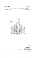
- FIGURE 1 is a longitudinal sectional view through a first embodiment of inventive apparatus incorporating a rotatably entrained press piston or ram as the feed element;
- FIGURE 2 is a cross-sectional view through an apertured plate of the apparatus of FIGURE 1, taken along the line IIII thereof;
- FIGURE 3 is a cross-sectional view of the apparatus of FIGURE 1, taken along the line IIIIII thereof;
- FIGURE 4 is a longitudinal sectional view through a further embodiment of inventive apparatus equipped with an idle independently rotating form as the feed element;
- FIGURE 5 is a longitudinal sectional view through a sealing portion of a further embodiment of apparatus incorporating a rotating press piston or ram as the feed element and independently oscillating kneading elements.
- the housing H of the apparatus is composed of an infeed portion 1, the intermediate plates 2 and 3, as well as the discharge portion 4.
- perforated or apertured plates 5, 6 and 7 are mounted be-' tween these housing portions 1, 2, 3 and 4, by means of the schematically illustrated screws 8 or equivalent fastening expedients.
- the housing portions 1, 2, 3 and 4 as well as also the apertured plates 5, 6 and 7 can be electrically heated by means of induction or resistance wires, or further can also be heated or cooled by a suitable fluid heat transmission agent.
- a piston or ram 20 located in the housing H functions as a feed element, and includes an extended portion or rod 21 having a substantially polygonal cross-sectional configuration, to which socalled stirrer-worms 22 and 23 are secured.
- the piston 20 and the stirrer elements 22 and 23 carry out the following movements in the present embodiment, namely: Firstly, a slow axial up and down feed movement, secondly, a superimposed rapid axial oscillation Which imparts to the product strong or pronounced impulse movements, as well as thirdly, a rotation which particularly acts as a mixing motion of the stirrer elements between the aperture plates and upon the product.
- the product for instance a plastic, which is to be processed or melted or plasticized, is filled into the infeed housing portion or funnel 1 in the form of powder or granulate.
- the granulate or the like flows into the pressure or compression compartment 51 located above the first perforated or apertured plate 5.
- the product is pressed through the uppermost apertured plate 5.
- new product again flows into the infeed housing portion 1, and when there is a renewed downward movement of this piston 20 this new product is also pressed through the apertured plates, so that a continuous feed motion is obtained from the infeed end to the discharge end of the apparatus.
- the embodiment of apparatus depicted in FIGURE 4 only employs a rotating worm 30 as the feed element, and which is rotatably driven by the schematically depicted drive means 53.
- the rotating and oscillating stirrer elements 31 and 32 are secured to a substantially polygonal-shaped portion 33 of a shaft 34 which extends through the central bore 54 of the worm 30 to a schematically illustrated drive mechanism 55.
- the worm 30 only rotates, whereas the shaft 34 rotates and oscillates independently thereof.
- a suitable worm groove 36 prevents throughpassage of the product between the worm 30 and the stirrer shaft 34.
- the mode of operation is the same as that considered with regard to the embodiments of- FIGURES 1 to 3.
- the Worm 30 serving as the feed element permits a completely continuous mode of operation and a compact construction of the apparatus since, owing to the elimination of the axial feed movement of the press ram or piston of FIGURE 1, here the spacing between the apertured plates 5, 6 and 7 can be maintained smaller.
- a press piston or ram 41 is rotatably coupled by a key member 42 or the like with a stirrer shaft 43 and the stirrer elements 44 secured thereon.
- the oscil lations of the stirrer shaft 43 take place independently of the press piston or ram 41, whereby a membrane 45, on the one hand, provides the necessary freedom of axial motion and, on the other hand, insures for the sealing between the press ram or piston 41 and the stirrer shaft 43.
- a schematically depicted drive mechanism 56 imparts the requisite movement to the aforedescribed elements.
- Apparatus for the thermal treatment such as heating, cooling, melting, plasticizing and crystallizing of plastic products, comprising, in combination,
- Apparatus as defined in claim 1, wherein said means for subjecting the product to a pronounced oscillation comprises means for rotating and oscillating said stirrer and kneading elements independently of the movement of said feed means.
- Apparatus as defined in claim 1 further including means for rotating said feed means together with said stirrer and kneading elements, the oscillation of said stirrer and kneading elements occurring independently thereof.
- Apparatus as defined in claim 1, wherein said means for subjecting the product to a pronounced oscillation includes means for rotating and oscillating said feed means together with said stirrer and kneading elements.
Landscapes
- Engineering & Computer Science (AREA)
- Mechanical Engineering (AREA)
- Chemical & Material Sciences (AREA)
- Chemical Kinetics & Catalysis (AREA)
- Dispersion Chemistry (AREA)
- Physics & Mathematics (AREA)
- Thermal Sciences (AREA)
- Manufacturing & Machinery (AREA)
- Processing And Handling Of Plastics And Other Materials For Molding In General (AREA)
- Mixers Of The Rotary Stirring Type (AREA)
Description
DEC. 2, H. LIST APPARATUS FOR THE THERMAL TREATMENT OF PLASTIC MATERIALS Filed Aug. 18, 1967 2 Sheets-Sheet 1 Fig. 1
\ A Wm o:
A Claims priority, application Switzerland, Aug. 22, 1966,
12,184/66 Int. Cl. B2915 3/02 U.S. Cl. 18--12 Claims ABSTRACT OF THE DISCLOSURE An apparatus for the thermal treatment, such as heating, cooling, melting, plasticizing and crystallizing plastic products which comprises a housing means and a plurality of heated or cooled perforated or apertured plates arranged behind one another in the aforesaid housing means. Additionally, stirrer and kneading elements are disposed between the apertured plates, and feed means L BACKGROUND OF THE INVENTION The present invention relates to an improved apparatus for the thermal treatment, such as for instance heating, cooling, fusing, plasticizing and crystallization of plastic products.
The plastic, highly viscous, aggregate condition presents particular problems for the heat transmission, particularly with products having a small coefficient of thermal conductivity. The rapid renewal of the boundary layers at the heattransmitting surfaces required for the heat trans fer and the pronounced movement of the product which is indispensible for convection, necessitates special mechanical stirrerand kneading means. Even so, the nonetheless low heat transmission factor additionally further requires large heat transfer surfaces at product layers which are as thin as possible.
. Prior art solutions of the problem resort to kneading rollers or drums and worm kneaders which are of single or multi-shaft constructions. Of these, one physical embodiment is particularly worthy of mention, and wherein the worm carries out in addition to its rotation an axially oscillating movement. In this case, heat is transmitted by the worm and the housing. The worm acts as a feed element and heat transfer surface. On the other hand, kneading worms which only rotate are also known to the art, and wherein the kneading action is increased by the provision of unheated perforated or apertured plates between the worm spirals or helixes.
SUMMARY OF THE INVENTION Accordingly, it is a primary object of the present invention to provide an improved apparatus for the thermal treatment of plastic products which effectively overcomes the drawbacks of the prior art structures heretofore mentioned.
Another, more specific object of the present invention relates to an improved apparatus for the thermal treatment of plastic products which is relatively simple in construction, economical to manufacture, highly reliable and efiicient in its operation, and not readily subject to breakdown.
"ice
Now, it has been found that the heat transfer or transmission at plastic, highly viscous materials can be carried out quite efiective'ly in an apparatus embodying a housing having a worm or a piston as the feed element for pressing the product through apertured plates which are heated or cooled and arranged behind. one another, and wherein stirrerand kneading elements are arranged between the aforementioned apertured plates. The inventive apparatus is characterized by the: features that the apparatus is constructed in such a manner that the product along its feed path is subjected to a pronounced oscillation by Carrying out an oscillatory movement between the stirrerand kneading elements and the surfaces of the apertured plates or housing. As a result, there is not only imparted a rotational movement to the product, but also a pronounced oscillatory movement which considerably improves the heat transfer factor.
BRIEF DESCRIPTION OF THE DRAWINGS The invention will be better understood, and objects other than those set forth above, will become apparent, when consideration is given to the following detailed description thereof. Such description makes reference to the annexed drawings wherein:
FIGURE 1 is a longitudinal sectional view through a first embodiment of inventive apparatus incorporating a rotatably entrained press piston or ram as the feed element;
FIGURE 2 is a cross-sectional view through an apertured plate of the apparatus of FIGURE 1, taken along the line IIII thereof;
FIGURE 3 is a cross-sectional view of the apparatus of FIGURE 1, taken along the line IIIIII thereof;
FIGURE 4 is a longitudinal sectional view through a further embodiment of inventive apparatus equipped with an idle independently rotating form as the feed element; and
FIGURE 5 is a longitudinal sectional view through a sealing portion of a further embodiment of apparatus incorporating a rotating press piston or ram as the feed element and independently oscillating kneading elements.
DESCRIPTION OF THE PREFERRED EMBODIMENTS Describing now the drawings, in the exemplary embodiment of apparatus depicted in FIGURE 1 and the associated cross-sectional views of FIGURES 2 and 3, the housing H of the apparatus is composed of an infeed portion 1, the intermediate plates 2 and 3, as well as the discharge portion 4. Further, it will be recognized that perforated or apertured plates 5, 6 and 7 are mounted be-' tween these housing portions 1, 2, 3 and 4, by means of the schematically illustrated screws 8 or equivalent fastening expedients. Additionally, it should be understood that the housing portions 1, 2, 3 and 4 as well as also the apertured plates 5, 6 and 7 can be electrically heated by means of induction or resistance wires, or further can also be heated or cooled by a suitable fluid heat transmission agent.
In the represented figures there has only been shown the arrangement of the heating channels 9 and 10 at the apertured plates 5, 6 and 7. These channels 9 and 10 are arranged in two planes located between the rows of apertures or bores 50. After these channels 9 and 10 are bored or otherwise formed they are sealed at their ends by the stoppers 15, with the exception of the inlet 11 which is provided with the pipe or nipple 12 and the outlet 13 which is provided with the pipe or nipple 14. These pipes or nipples 12 and 14 are situated diametrically opposite one another, in other words at opposite sides of the associated apertured plate member 5, 6 or 7. The heat transmission agent which enters through the infeed nipple or pipe 12 divides into two streams at the intersection of the channels 9 and 10, is again combined and discharges at the discharge pipe 14. A piston or ram 20 located in the housing H functions as a feed element, and includes an extended portion or rod 21 having a substantially polygonal cross-sectional configuration, to which socalled stirrer- worms 22 and 23 are secured. The piston 20 and the stirrer elements 22 and 23 carry out the following movements in the present embodiment, namely: Firstly, a slow axial up and down feed movement, secondly, a superimposed rapid axial oscillation Which imparts to the product strong or pronounced impulse movements, as well as thirdly, a rotation which particularly acts as a mixing motion of the stirrer elements between the aperture plates and upon the product.
The product, for instance a plastic, which is to be processed or melted or plasticized, is filled into the infeed housing portion or funnel 1 in the form of powder or granulate. In the upper position of the piston 20 shown in full lines, the granulate or the like flows into the pressure or compression compartment 51 located above the first perforated or apertured plate 5. During descent of the piston 20, until it assumes the phantom line position of FIGURE 1, the product is pressed through the uppermost apertured plate 5. After the piston 20 has been retracted and assumes the starting position, new product again flows into the infeed housing portion 1, and when there is a renewed downward movement of this piston 20 this new product is also pressed through the apertured plates, so that a continuous feed motion is obtained from the infeed end to the discharge end of the apparatus.
Owing to the rotation of the stirringand kneading elements 22, 23 which are disposed between the heated apertured plates 5, 6 and 7, the product is always thoroughly mixed and homogenized. However, the product is subjected to particularly strong motion impulses by virtue of the additional axial oscillation of the aforementioned stirrer elements. The requisite movement of the aforedescribed components can be obtained by any suitable drive mechanism known to the art and which has been schematically depicted in FIGURE 1 by reference numeral 52. Furthermore, it should be understood that the excellent effect of the apparatus can be attributed, on the one hand, to the large shearing forces to which the product is subjected owing to the throttle action of the apertured plates 5, 6 and 7 and the rotation and oscillation of the stirrer elements 22 and 23. These shearing forces are transformed directly at the product into heat. Additionally, there is added the quantity of heat which is directly transmitted from the heated surfaces to the product. On the one hand, these surfaces are considerably enlarged by virtue of the apertured plates with respect to the conventional apparatuses. On the other hand, the heat transfer is improved by the differences in velocity which occur during oscillation. In many cases, the mechanical generation of heat is so great that the apertured plates 5, 6 and 7 must be cooled.
The embodiment of apparatus depicted in FIGURE 4 only employs a rotating worm 30 as the feed element, and which is rotatably driven by the schematically depicted drive means 53. The rotating and oscillating stirrer elements 31 and 32 are secured to a substantially polygonal-shaped portion 33 of a shaft 34 which extends through the central bore 54 of the worm 30 to a schematically illustrated drive mechanism 55. It will be understood that the worm 30 only rotates, whereas the shaft 34 rotates and oscillates independently thereof. A suitable worm groove 36 prevents throughpassage of the product between the worm 30 and the stirrer shaft 34. The mode of operation is the same as that considered with regard to the embodiments of- FIGURES 1 to 3. The Worm 30 serving as the feed element, however, permits a completely continuous mode of operation and a compact construction of the apparatus since, owing to the elimination of the axial feed movement of the press ram or piston of FIGURE 1, here the spacing between the apertured plates 5, 6 and 7 can be maintained smaller.
Finally, reference is made to the embodiment of apparatus depicted in FIGURE 5 which incorporates a further variation of the movements of the elements. More precisely, a press piston or ram 41 is rotatably coupled by a key member 42 or the like with a stirrer shaft 43 and the stirrer elements 44 secured thereon. The oscil lations of the stirrer shaft 43, however, take place independently of the press piston or ram 41, whereby a membrane 45, on the one hand, provides the necessary freedom of axial motion and, on the other hand, insures for the sealing between the press ram or piston 41 and the stirrer shaft 43. Once again, a schematically depicted drive mechanism 56 imparts the requisite movement to the aforedescribed elements. I
The movements heretofore described with the various embodiments depicted in the figures of the drawings, by way of example, can be carried out not only with a worm as the feed element but also with a press ram or piston as the feed element. Likewise, the feed movement can be carried out, in known manner, horizontally or inclined, and the heating and cooling can can be performed in individual, separate zones. Also, the different discharge forms, as such are known in presses of all types, can also be combined without difiiculty with the inventive embodiments of apparatus.
While there is shown and described present preferred embodiments of the invention, it is to be distinctly understood that the invention is not limited thereto but may be otherwise variously embodied and practiced within the scope of the following claims.
Accordingly, what is claimed is:
1. Apparatus for the thermal treatment, such as heating, cooling, melting, plasticizing and crystallizing of plastic products, comprising, in combination,
(a) housing means,
(b) a plurality of temperature-controlled apertured plates arranged behind one another in said housing means,
(0) stirrer and kneading elements disposed between said apertured plates,
((1) feed means for pressing the product through said apertured plates, and
(e) means for subjecting the product during its feed through said housing means to a pronounced oscillation by carrying out an oscillatory movement between said stirrer and kneading elements and said apertured plates.
2. Apparatus as defined in claim 1, wherein said temperature-controlled apertured plates are heated.
3. Apparatus as defined in claim 1, wherein said temperature-controlled apertured plates are cooled.
4. Apparatus as defined in claim 1, wherein said feed means comprises a press piston.
5. Apparatus as defined in claim 1, wherein said feed means comprises a worm means.
6. Apparatus as defined in claim 1, wherein said means for subjecting the product to a pronounced oscillation comprises means for rotating and oscillating said stirrer and kneading elements independently of the movement of said feed means.
7. Apparatus as defined in claim 1, further including means for rotating said feed means together with said stirrer and kneading elements, the oscillation of said stirrer and kneading elements occurring independently thereof.
8. Apparatus as defined in claim 1, wherein said feed means oscillates together with said stirrer and kneading elements, whereas the rotation of said stirrer and kneading elements takes place independently thereof.
9. Apparatus as defined in claim 1, wherein said means for subjecting the product to a pronounced oscillation includes means for rotating and oscillating said feed means together with said stirrer and kneading elements.
10. Apparatus as defined in claim 1, wherein said apertured plates are of substantially sieve-like construction.
Fenske et a1. 23-284 Braibante et al. Braunlich 259-4 X R Westrich et a1. -1--- 259-4 XR Stanley. McWhirter 2594 WILLIAM J. STEPHENSON, Primary Examiner
Applications Claiming Priority (1)
| Application Number | Priority Date | Filing Date | Title |
|---|---|---|---|
| CH1218466A CH454432A (en) | 1966-08-22 | 1966-08-22 | Apparatus for the thermal treatment of plastic materials |
Publications (1)
| Publication Number | Publication Date |
|---|---|
| US3480997A true US3480997A (en) | 1969-12-02 |
Family
ID=4380663
Family Applications (1)
| Application Number | Title | Priority Date | Filing Date |
|---|---|---|---|
| US661659A Expired - Lifetime US3480997A (en) | 1966-08-22 | 1967-08-18 | Apparatus for the thermal treatment of plastic materials |
Country Status (2)
| Country | Link |
|---|---|
| US (1) | US3480997A (en) |
| CH (1) | CH454432A (en) |
Cited By (16)
| Publication number | Priority date | Publication date | Assignee | Title |
|---|---|---|---|---|
| US4057379A (en) * | 1974-06-04 | 1977-11-08 | Sato Iron Works Co., Ltd. | Kneading and extruding apparatus for extrudable material |
| US4089917A (en) * | 1974-05-16 | 1978-05-16 | Ikegai Tekko Kabushiki Kaisha | Process of cross-linking and extrusion molding thermoplastic polymers |
| US4151242A (en) * | 1975-01-15 | 1979-04-24 | Sussex Plastics Engineering Inc. | Method for extruding plastics |
| FR2418074A1 (en) * | 1978-02-23 | 1979-09-21 | Lavorazione Mat Plast | SCREW EXTRUDER FOR THERMOPLASTIC SYNTHETIC FOAMS |
| US4304054A (en) * | 1980-04-21 | 1981-12-08 | The B. F. Goodrich Company | Screw press for drying elastomeric polymers |
| US4376747A (en) * | 1980-12-11 | 1983-03-15 | Union Carbide Corporation | Process for controlling the cross-sectional structure of mesophase pitch derived fibers |
| US4810443A (en) * | 1987-07-02 | 1989-03-07 | Dow Corning Coporation | Method for forming filaments from a resin |
| US4814187A (en) * | 1987-01-13 | 1989-03-21 | Ngk Insulators, Ltd. | Honeycomb structural body-extruding die apparatus |
| EP0319435A1 (en) * | 1987-12-04 | 1989-06-07 | Skis Rossignol S.A. | Process for altering the sliding characteristics of a ski sole made of powdered high-density highly specific gravity polyethylene |
| WO1990002034A1 (en) * | 1988-08-16 | 1990-03-08 | Thomas Engel | Device and process for shaping semi-finished products from high molecular weight plastics |
| US4976904A (en) * | 1989-04-20 | 1990-12-11 | Energy Research Corporation | Method and apparatus for continuous formation of fibrillated polymer binder electrode component |
| US5041249A (en) * | 1989-12-26 | 1991-08-20 | Exxon Chemical Patent Inc. | Process for low-temperature elastomer finishing |
| US5962728A (en) * | 1997-10-31 | 1999-10-05 | Arco Chemical Technology, L.P. | Isocyanate residue purification |
| EP1232847A1 (en) * | 2001-02-14 | 2002-08-21 | COLMEC S.p.A. | Pin-barrel extruder |
| US20020185771A1 (en) * | 2001-05-02 | 2002-12-12 | The Japan Steel Works, Ltd. | Method and apparatus for making pellets of wood meal compound |
| JP2022527315A (en) * | 2019-03-29 | 2022-06-01 | トーレ プラスティックス (アメリカ) インコーポレイテッド | Liquid injection barrel element for barrel extruder |
Families Citing this family (2)
| Publication number | Priority date | Publication date | Assignee | Title |
|---|---|---|---|---|
| JPS555948A (en) * | 1978-06-29 | 1980-01-17 | Nitto Chem Ind Co Ltd | Cooling of hydrous polymer gel mass |
| SE8800175L (en) * | 1988-01-20 | 1989-07-21 | Bo Nilsson | PROCEDURE AND DEVICE FOR CHANGING THE TEMPERATURE OF A PLASTIC MASS THROUGH COOLING OR HEATING ITS |
Citations (7)
| Publication number | Priority date | Publication date | Assignee | Title |
|---|---|---|---|---|
| US1796772A (en) * | 1927-06-16 | 1931-03-17 | Carbondale Machine Co | Distillate-chilling apparatus |
| US2635949A (en) * | 1949-03-24 | 1953-04-21 | Standard Oil Dev Co | Apparatus for contacting solids with fluids |
| US2712799A (en) * | 1953-02-21 | 1955-07-12 | Braibanti Mario | Apparatus for treating alimentary pastes and the like |
| US2815532A (en) * | 1953-05-25 | 1957-12-10 | American Viscose Corp | Spinneret mixing element |
| US2893846A (en) * | 1956-06-21 | 1959-07-07 | Shell Dev | Fluid mixer with rotating baffles |
| US3035303A (en) * | 1958-11-14 | 1962-05-22 | Ici Ltd | Extrusion of organic thermoplastic polymeric materials |
| US3408051A (en) * | 1966-02-23 | 1968-10-29 | Mixing Equipment Co Inc | Column mixing apparatus |
-
1966
- 1966-08-22 CH CH1218466A patent/CH454432A/en unknown
-
1967
- 1967-08-18 US US661659A patent/US3480997A/en not_active Expired - Lifetime
Patent Citations (7)
| Publication number | Priority date | Publication date | Assignee | Title |
|---|---|---|---|---|
| US1796772A (en) * | 1927-06-16 | 1931-03-17 | Carbondale Machine Co | Distillate-chilling apparatus |
| US2635949A (en) * | 1949-03-24 | 1953-04-21 | Standard Oil Dev Co | Apparatus for contacting solids with fluids |
| US2712799A (en) * | 1953-02-21 | 1955-07-12 | Braibanti Mario | Apparatus for treating alimentary pastes and the like |
| US2815532A (en) * | 1953-05-25 | 1957-12-10 | American Viscose Corp | Spinneret mixing element |
| US2893846A (en) * | 1956-06-21 | 1959-07-07 | Shell Dev | Fluid mixer with rotating baffles |
| US3035303A (en) * | 1958-11-14 | 1962-05-22 | Ici Ltd | Extrusion of organic thermoplastic polymeric materials |
| US3408051A (en) * | 1966-02-23 | 1968-10-29 | Mixing Equipment Co Inc | Column mixing apparatus |
Cited By (22)
| Publication number | Priority date | Publication date | Assignee | Title |
|---|---|---|---|---|
| US4089917A (en) * | 1974-05-16 | 1978-05-16 | Ikegai Tekko Kabushiki Kaisha | Process of cross-linking and extrusion molding thermoplastic polymers |
| US4057379A (en) * | 1974-06-04 | 1977-11-08 | Sato Iron Works Co., Ltd. | Kneading and extruding apparatus for extrudable material |
| US4151242A (en) * | 1975-01-15 | 1979-04-24 | Sussex Plastics Engineering Inc. | Method for extruding plastics |
| FR2418074A1 (en) * | 1978-02-23 | 1979-09-21 | Lavorazione Mat Plast | SCREW EXTRUDER FOR THERMOPLASTIC SYNTHETIC FOAMS |
| US4304054A (en) * | 1980-04-21 | 1981-12-08 | The B. F. Goodrich Company | Screw press for drying elastomeric polymers |
| US4376747A (en) * | 1980-12-11 | 1983-03-15 | Union Carbide Corporation | Process for controlling the cross-sectional structure of mesophase pitch derived fibers |
| US4814187A (en) * | 1987-01-13 | 1989-03-21 | Ngk Insulators, Ltd. | Honeycomb structural body-extruding die apparatus |
| US4810443A (en) * | 1987-07-02 | 1989-03-07 | Dow Corning Coporation | Method for forming filaments from a resin |
| EP0319435A1 (en) * | 1987-12-04 | 1989-06-07 | Skis Rossignol S.A. | Process for altering the sliding characteristics of a ski sole made of powdered high-density highly specific gravity polyethylene |
| FR2624028A1 (en) * | 1987-12-04 | 1989-06-09 | Rossignol Sa | PROCESS FOR IMPROVING THE SLIDING PROPERTIES OF A HIGH DENSITY POLYETHYLENE SKI SOLE, AND OF VERY HIGH MOLECULAR WEIGHT |
| WO1990002034A1 (en) * | 1988-08-16 | 1990-03-08 | Thomas Engel | Device and process for shaping semi-finished products from high molecular weight plastics |
| US4976904A (en) * | 1989-04-20 | 1990-12-11 | Energy Research Corporation | Method and apparatus for continuous formation of fibrillated polymer binder electrode component |
| US5041249A (en) * | 1989-12-26 | 1991-08-20 | Exxon Chemical Patent Inc. | Process for low-temperature elastomer finishing |
| US5962728A (en) * | 1997-10-31 | 1999-10-05 | Arco Chemical Technology, L.P. | Isocyanate residue purification |
| EP1232847A1 (en) * | 2001-02-14 | 2002-08-21 | COLMEC S.p.A. | Pin-barrel extruder |
| WO2002068174A1 (en) * | 2001-02-14 | 2002-09-06 | Colmec S.P.A. | Screw extruder with improved mixing pins |
| US20040115297A1 (en) * | 2001-02-14 | 2004-06-17 | Ubaldo Colombo | Screw extruder with improved mixing pins |
| US6814481B2 (en) | 2001-02-14 | 2004-11-09 | Colmec S.P.A. | Screw extruder with improved mixing pins |
| US20020185771A1 (en) * | 2001-05-02 | 2002-12-12 | The Japan Steel Works, Ltd. | Method and apparatus for making pellets of wood meal compound |
| US7029262B2 (en) * | 2001-05-02 | 2006-04-18 | The Japan Steel Works, Ltd. | Method and apparatus for making pellets of wood meal compound |
| JP2022527315A (en) * | 2019-03-29 | 2022-06-01 | トーレ プラスティックス (アメリカ) インコーポレイテッド | Liquid injection barrel element for barrel extruder |
| JP7530910B2 (en) | 2019-03-29 | 2024-08-08 | トーレ プラスティックス (アメリカ) インコーポレイテッド | Liquid injection barrel elements for barrel extruders |
Also Published As
| Publication number | Publication date |
|---|---|
| DE1679854B1 (en) | 1972-10-26 |
| CH454432A (en) | 1968-04-15 |
Similar Documents
| Publication | Publication Date | Title |
|---|---|---|
| US3480997A (en) | Apparatus for the thermal treatment of plastic materials | |
| US2615199A (en) | Material treating apparatus | |
| US3310837A (en) | Plasticizing device for extrusion or injection molding | |
| US3664795A (en) | Screw extruders with dual section ejection zone | |
| US2631016A (en) | Homogenizing device for extruding machines | |
| US3164375A (en) | Apparatus for intensive mixing | |
| CA1223416A (en) | Method and apparatus for extruding thermoplastic material | |
| US3866890A (en) | Apparatus for simultaneous plasticating and mixing | |
| CN1134684A (en) | Multi-screw continuous mixers for plasticizable compounds | |
| US3749375A (en) | Process for mixing, kneading and granulating thermosetting plastic material in continuous operation | |
| US3946998A (en) | Single worm extruder | |
| US6227692B1 (en) | Double wave screw | |
| US3467743A (en) | Apparatus for the extrusion of plastics | |
| US3122356A (en) | Worm arrangement | |
| US3325864A (en) | Plastic extruder | |
| US3787160A (en) | Apparatus having extrusion and mixing zones | |
| US3278986A (en) | Plastic compounder | |
| US3262154A (en) | Extruders for plastic material | |
| US3488416A (en) | Elastic melt extruder and method of operation | |
| EP0048926B1 (en) | High efficiency, fast extruders for extruding and refining soap and detergents | |
| RU2501501C1 (en) | Double-screw extruder | |
| US3695585A (en) | Mixing and plasticizing machine and process for operating said machine | |
| US3583684A (en) | Mixing and reaction extruder | |
| US3192564A (en) | Worm press for kneading and displacing plastic masses | |
| US3325865A (en) | Extrusion process and apparatus |