US3476868A - Cable spreader - Google Patents
Cable spreader Download PDFInfo
- Publication number
- US3476868A US3476868A US712807A US3476868DA US3476868A US 3476868 A US3476868 A US 3476868A US 712807 A US712807 A US 712807A US 3476868D A US3476868D A US 3476868DA US 3476868 A US3476868 A US 3476868A
- Authority
- US
- United States
- Prior art keywords
- cable
- receptacles
- spreader
- insulator
- multiplex
- Prior art date
- Legal status (The legal status is an assumption and is not a legal conclusion. Google has not performed a legal analysis and makes no representation as to the accuracy of the status listed.)
- Expired - Lifetime
Links
- 239000012212 insulator Substances 0.000 description 31
- 230000002093 peripheral effect Effects 0.000 description 5
- 230000007935 neutral effect Effects 0.000 description 3
- 230000003247 decreasing effect Effects 0.000 description 2
- 238000009434 installation Methods 0.000 description 2
- 230000014759 maintenance of location Effects 0.000 description 2
- 238000000034 method Methods 0.000 description 2
- 239000007787 solid Substances 0.000 description 2
- 230000006835 compression Effects 0.000 description 1
- 238000007906 compression Methods 0.000 description 1
- 238000001816 cooling Methods 0.000 description 1
- 238000001746 injection moulding Methods 0.000 description 1
- 238000003780 insertion Methods 0.000 description 1
- 230000037431 insertion Effects 0.000 description 1
- 238000012986 modification Methods 0.000 description 1
- 230000004048 modification Effects 0.000 description 1
- 230000008520 organization Effects 0.000 description 1
- 229920003023 plastic Polymers 0.000 description 1
- 239000004033 plastic Substances 0.000 description 1
- 229920000915 polyvinyl chloride Polymers 0.000 description 1
- 230000007480 spreading Effects 0.000 description 1
Images
Classifications
-
- H—ELECTRICITY
- H02—GENERATION; CONVERSION OR DISTRIBUTION OF ELECTRIC POWER
- H02G—INSTALLATION OF ELECTRIC CABLES OR LINES, OR OF COMBINED OPTICAL AND ELECTRIC CABLES OR LINES
- H02G7/00—Overhead installations of electric lines or cables
- H02G7/12—Devices for maintaining distance between parallel conductors, e.g. spacer
Definitions
- Multiplex cables are widely used for transmitting electric power.
- a common example is a triplex cable which includes a bare neutral cable twisted together with a pair of insulated wires. While such cables have distinct advantages, it has been difiicult to make a service connection in order to deliver current from a span of cable to a point where it is to be utilized. Accordingly, devices known as cable spreaders have been developed to separate the cable strands of a multiplex cable, allowing the convenient installation of a service connection.
- the present invention provides an improved multiplex cable spreader which comprises a unitary insulator of generally annular configuration, and having a plurality of equi-distant, peripheral, generally C-shaped cable receptacles.
- the cable receptacles have openings or slots directed radially outwardly from the outside of the insulator, the slots being at least equal in width to the largest-diameter strand of the mutiplex cable on which it is to be employed.
- the C-shaped receptacles are defined by opposite, concave side walls so that the widest point in the interior of the receptacles is relatively wider than the opening at the outer periphery of the cable spreader.
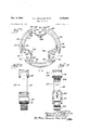
- FIGURE 1 is a front elevation view of the preferred embodiment of the present invention for use with triplex cable
- FIGURE 2 is a side elevation view of the device shown in FIGURE 1;
- FIGURE 3 is a cross-sectional view taken along line 3-3 of FIGURE 1;
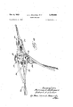
- FIGURE 4 is a perspective view of the preferred em- 3,476,868 Patented Nov. 4, 1969 bodiment of the present invention in spreading engagement with a triplex cable, and also showing a service connection anchored by a dead end.
- FIGURES l-3 illustrate the preferred cable spreader of the present invention, generally indicated by reference numeral 10.
- reference numeral 10 illustrates the preferred cable spreader of the present invention, generally indicated by reference numeral 10.
- the embodiment shown is designed for use with triplex cable, i.e., that having three separate cable strands, it will be understood that the invention is equally adaptable to other types of multiplex cable.
- the cable spreader 10 is formed by a generally annular insulator 12 preferably having a relatively large central aperture 14.
- a plurality of C-shaped cable receptacles generally 16.
- the number of cable receptacles 16 must be equal to the number of strands in the multiplex cable to be spread. In the embodiment shown, there are three such receptacles 16 for use with triplex cable.
- Each of the C-shaped receptacles 16 has an opening 18 at the outside edge of the annular insulator 12, and directed radially outwardly from the insulator 12.
- each In order to form the C-shape of the cable receptacles 16, it is necessary that each have opposite, facing, concave side walls 20. This design makes possible the easy insertion of a cable strand through the opening 18, and
- each of the C-shaped cable receptacles 16 has a convex hump 22 on the inner portion opposite the opening 18.
- the convex hump 22 urges a cable in the receptacle toward one of the concave side walls 20, thus decreasing the chances that the cable spreader 10 will become disengaged from the cables in use, as described below.
- the convex hump 22 extends toward the opening 18 a distance less than the depth of its associated receptacle 16.
- the interior of the cable spreader 10 is formed into inward protrusions 24 opposite the openings 18 in the cable receptacles 16.
- the protrusions 24 divide the central aperture 14 of the annular insulator 12 into equal segments, making convenient the retention of a dead end.
- the most preferred device may also include tie wire openings 26 in the annular insulator 12 adjacent to the cable receptacles 16. Although tie wires are not generally required to secure cables into the receptacle, they may be employed under extreme conditions, and therefore, the tie wire openings 26 are preferably included in the device. Also included in the most preferred embodiment are elongated, arcuate slots 28 along the annular insulator 12 between the cable receptacles 16.
- slots 28 aid in decreasing the weight of the device, and also, by eliminating areasof solid mass from the inner periphery to the outer periphery along any substantial portion of the insulator, allow for even cooling so that the cable spreader 10 may be easily manufactured by injection molding techniques from plastics such as (poly)vinyl chloride.
- the cable spreader 10 of the present invention is shown in engagement with a twisted triplex cable, generally 30.
- the cable 30 includes two insulated strands 32 and a bare, ground strand 34, which also serves to support the triplex cable.
- the cable spreader 10 is inserted between the separated cables, with a strand 32, 34 in each of the C-shaped cable receptacles 16. Because the cable 30 is twisted, all of the strands 32, 34 will be biased radially inwardly toward the center of the cable spreader 10.
- the convex humps 22 and the bottom of the C-shaped cable receptacles 16 will urge the cable strands 32, 34 toward the opposite, concave side walls 20. This positioning of the cables minimizes the likelihood that one of the strands 32, 34 will come out under the force of high winds or the like.
- the service connections to each of the cable strands 32, 34 Adjacent to, the cable spreader 10, there are depicted service connections to each of the cable strands 32, 34.
- the service connections to the insulated strands 32 are preferably covered by insulated covers 36, while the connection to the bare neutral strand 34 is a simple compression connector 38, which need not be insulated.
- the service connection is preferably secured to the cable spreader by a dead end 40 wrapped around at least one of the strands of the service connection. As shown in FIGURE 4, the dead end may be conveniently wrapped around the bare neutral strand 34 of the service connection, with the bight of the dead end passing through the center aperture 14 of the cable spreader 10, maintained in position between a pair of protrusions 24.
- the C-shaped cable receptacles 16 be identical, since one size is adaptable to many sizes of individual cable strands.
- the only essential requirement is that the open ings 18 be at least equal to the diameter of the largest diameter strands in the multiplex cable being utilized.
- the cable spreader 10 be of symmetrical design. Referring to FIGURE 1, the device should be symmetrical about a plane perpendicular to the plane of the annular insulator 12, and passing through the geometric center of one of the C-shaped cable receptacles 16 and the center of the annular insulator 12. This is the plane along which FIGURE 3 has been taken.
- a multiplex cable spreader comprising: a unitary generally annular insulator having a plurality of equidistant, peripheral, generally C-shaped cable receptacles, said receptacles having openings directed radially outwardly from the outside of said insulator, said openings at least equalin width to the diameter of the cable strands of said multiplex cable, and said receptacles each having opposite, concave side walls and a convex hump on the inner portion opposite said openings to urge a cable strand of said multiplex cable toward one of said side walls, said hump extending toward said opening a'distance less than the depth of said receptacle.
- a multiplex cable spreader comprising: a unitary 7 generally annular insulator having a plurality of equidistant peripheral, generally C-shaped cable receptacles, said receptacles having openings directed radially outwardly from the outside of said insulator, said openings at least equal in width to the diameter of the cable strands of said multiplex cable, and said receptacles each having opposite, concave side walls and a convex hump on the inner portion opposite said openings to urge a cable strand of said multiplex cable toward one of said side walls; and a plurality of protrusions on the inner sides of said cable receptacles, said protrusions defining regionsaround the interior of said insulator for engagement by the bight of a dead end.
- a multiplex cable spreader comprising: a unitary, generally annular insulator having a plurality of equidistant, peripheral, generally C-shaped cable receptacles, said receptacles having openings directed radially outwardly from the outer periphery of said insulator, said openings at least equal in size to the cable strands of said multiplex cable, and said receptacles each having opposite, concave side walls and a convex hump opposite said opening to urge a cable strand toward one or said side walls, and said insulator having a relatively large central aperture; inward protrusions on the inner sides of said cable receptacles, said protrusions defining regions aroundthe interior of said insulator for engagement by thbight'bf'a-dead end; said insulator further including an elongated, arcuate slot between each pair of cable receptacles to eliminate areas of solid mass from inner periphery to outer periphery along any
- a cable connection comprising: a twisted, multiplex cable; a multiplex cable spreader formed by a unitary, generally annular insulator having a relatively large central aperture and a plurality of equidistant, peripheral, generally C-shaped cable receptacles having openings directed radially outwardly from the outside of said insulator, said openings at least equal in width to the diameter of thestrands of said multiplex cable, and said receptacles each having opposite, concave side walls anda convex hump opposite said opening, the numberof cablereceptacles being equaltothe number of cable strands included in in said multiplex cable, said cable spreader-disposed between the cable strands of said multiplex cable, each of said cable strands passing through one of said C-shaped cable receptacles whereby to spread the strands of said multiplex cable; a service connection to said multiplex cable adjacent to said cable spreader; and a dead end looped through said central aperture of said annular insulator and
Landscapes
- Cable Accessories (AREA)
Description
Nov. 4, 1969 I H. 1.. WILLIAMS ETAL 3,476,868
CABLE SPREADER Filed March 15, 1968 I I 2 Sheets-Sheet 1 Jiz yep a rs dVargLsvniZ W amQ 41% 67 5? ac/er. M Wm, 65
Nov; 4, 1969 H. L. WILLIAMS ETAL 3,476,868
CABLE SPREADER 2 Sheets-Sheet 2 Filed March 13, 1968 fiz erz ans. Jar 50ml; $0198); flfzlcer'.
g M, (ZM M 45;,
United States Patent 3,476,868 CABLE SPREADER Harrison L. Williams, Euclid, and Robert A. Eucker, Brooklyn, Ohio, assignors to Preformed Line Products Company, Cleveland, Ohio, a corporation of Ohio Filed Mar. 13, 1968, Ser. No. 712,807 Int. 'Cl. H02g .7/12, 7/20 US. Cl. 17443 9 Claims ABSTRACT OF THE DISCLQSURE The present invention relates to an improved multiplex cable spreader. v
Multiplex cables, especially twisted multiplex cables, are widely used for transmitting electric power. A common example is a triplex cable which includes a bare neutral cable twisted together with a pair of insulated wires. While such cables have distinct advantages, it has been difiicult to make a service connection in order to deliver current from a span of cable to a point where it is to be utilized. Accordingly, devices known as cable spreaders have been developed to separate the cable strands of a multiplex cable, allowing the convenient installation of a service connection.
A number of cable spreader designs have been developed but all have suffered froma number of disadvantages. Most cable spreaders require that the individual cable strands be lashed or tied to the spreader to prevent it from becoming disengaged. While some designs have used clamps to eliminate the need for lashing, they are complicated and expensive to produce. Finally, it is essential with most cable spreaders that they be installed with the proper orientation. This, along with the requirement for lashing, presents some difficulty, as Well as time wastage, for a person working on an electrical line.
' Generally, the present invention provides an improved multiplex cable spreader which comprises a unitary insulator of generally annular configuration, and having a plurality of equi-distant, peripheral, generally C-shaped cable receptacles. The cable receptacles have openings or slots directed radially outwardly from the outside of the insulator, the slots being at least equal in width to the largest-diameter strand of the mutiplex cable on which it is to be employed. The C-shaped receptacles are defined by opposite, concave side walls so that the widest point in the interior of the receptacles is relatively wider than the opening at the outer periphery of the cable spreader.
The invention, both as to its organization and method of operation, together with the objects and advantages thereof, will be best appreciated from the following detailed description taken together with the drawings, in which:
FIGURE 1 is a front elevation view of the preferred embodiment of the present invention for use with triplex cable;
FIGURE 2 is a side elevation view of the device shown in FIGURE 1;
FIGURE 3 is a cross-sectional view taken along line 3-3 of FIGURE 1; and
FIGURE 4 is a perspective view of the preferred em- 3,476,868 Patented Nov. 4, 1969 bodiment of the present invention in spreading engagement with a triplex cable, and also showing a service connection anchored by a dead end.
Referring to the drawings, FIGURES l-3 illustrate the preferred cable spreader of the present invention, generally indicated by reference numeral 10. Although the embodiment shown is designed for use with triplex cable, i.e., that having three separate cable strands, it will be understood that the invention is equally adaptable to other types of multiplex cable.
As shown in FIGURE 1, the cable spreader 10 is formed by a generally annular insulator 12 preferably having a relatively large central aperture 14. Around the periphery of the insulator 12 are a plurality of C-shaped cable receptacles generally 16. The number of cable receptacles 16 must be equal to the number of strands in the multiplex cable to be spread. In the embodiment shown, there are three such receptacles 16 for use with triplex cable. Each of the C-shaped receptacles 16 has an opening 18 at the outside edge of the annular insulator 12, and directed radially outwardly from the insulator 12.
In order to form the C-shape of the cable receptacles 16, it is necessary that each have opposite, facing, concave side walls 20. This design makes possible the easy insertion of a cable strand through the opening 18, and
-'the retention thereof by the receptacle 16 as hereinafter described.
Preferably, each of the C-shaped cable receptacles 16 has a convex hump 22 on the inner portion opposite the opening 18. The convex hump 22 urges a cable in the receptacle toward one of the concave side walls 20, thus decreasing the chances that the cable spreader 10 will become disengaged from the cables in use, as described below. As shown in FIGURE 1, the convex hump 22 extends toward the opening 18 a distance less than the depth of its associated receptacle 16.
In the most preferred embodiment, the interior of the cable spreader 10 is formed into inward protrusions 24 opposite the openings 18 in the cable receptacles 16. The protrusions 24 divide the central aperture 14 of the annular insulator 12 into equal segments, making convenient the retention of a dead end. The most preferred device may also include tie wire openings 26 in the annular insulator 12 adjacent to the cable receptacles 16. Although tie wires are not generally required to secure cables into the receptacle, they may be employed under extreme conditions, and therefore, the tie wire openings 26 are preferably included in the device. Also included in the most preferred embodiment are elongated, arcuate slots 28 along the annular insulator 12 between the cable receptacles 16. These slots 28 aid in decreasing the weight of the device, and also, by eliminating areasof solid mass from the inner periphery to the outer periphery along any substantial portion of the insulator, allow for even cooling so that the cable spreader 10 may be easily manufactured by injection molding techniques from plastics such as (poly)vinyl chloride.
Referring to FIGURE 4, the cable spreader 10 of the present invention is shown in engagement with a twisted triplex cable, generally 30. The cable 30 includes two insulated strands 32 and a bare, ground strand 34, which also serves to support the triplex cable. As shown, the cable spreader 10 is inserted between the separated cables, with a strand 32, 34 in each of the C-shaped cable receptacles 16. Because the cable 30 is twisted, all of the strands 32, 34 will be biased radially inwardly toward the center of the cable spreader 10. The convex humps 22 and the bottom of the C-shaped cable receptacles 16 will urge the cable strands 32, 34 toward the opposite, concave side walls 20. This positioning of the cables minimizes the likelihood that one of the strands 32, 34 will come out under the force of high winds or the like.
Adjacent to, the cable spreader 10, there are depicted service connections to each of the cable strands 32, 34. The service connections to the insulated strands 32 are preferably covered by insulated covers 36, while the connection to the bare neutral strand 34 is a simple compression connector 38, which need not be insulated. The service connection is preferably secured to the cable spreader by a dead end 40 wrapped around at least one of the strands of the service connection. As shown in FIGURE 4, the dead end may be conveniently wrapped around the bare neutral strand 34 of the service connection, with the bight of the dead end passing through the center aperture 14 of the cable spreader 10, maintained in position between a pair of protrusions 24.
For simplicity of installation, it is preferred that all of the C-shaped cable receptacles 16 be identical, since one size is adaptable to many sizes of individual cable strands. The only essential requirement is that the open ings 18 be at least equal to the diameter of the largest diameter strands in the multiplex cable being utilized. It is also preferred that the cable spreader 10 be of symmetrical design. Referring to FIGURE 1, the device should be symmetrical about a plane perpendicular to the plane of the annular insulator 12, and passing through the geometric center of one of the C-shaped cable receptacles 16 and the center of the annular insulator 12. This is the plane along which FIGURE 3 has been taken. This symmetry avoids any possibility of confusion in installing the I cable spreader 10, since it makes no difference whatever While the embodiments described herein are at present considered to be preferred, it will be understood that various modifications and improvements may be made therein without departing from the true spirit and scope of applicants invention.
We claim:
1. A multiplex cable spreader comprising: a unitary generally annular insulator having a plurality of equidistant, peripheral, generally C-shaped cable receptacles, said receptacles having openings directed radially outwardly from the outside of said insulator, said openings at least equalin width to the diameter of the cable strands of said multiplex cable, and said receptacles each having opposite, concave side walls and a convex hump on the inner portion opposite said openings to urge a cable strand of said multiplex cable toward one of said side walls, said hump extending toward said opening a'distance less than the depth of said receptacle.
2. A cablespreader as defined in claim 1 wherein said insulator has three generally C-shaped' cable receptacles for use with triplex cable.
3. A cable spreader as defined in claim 1 wherein said insulator includes a tie wire opening adjacent to each cable receptacle for lashing cables into said receptacles with tie wiresf 4. A multiplex cable spreader comprising: a unitary 7 generally annular insulator having a plurality of equidistant peripheral, generally C-shaped cable receptacles, said receptacles having openings directed radially outwardly from the outside of said insulator, said openings at least equal in width to the diameter of the cable strands of said multiplex cable, and said receptacles each having opposite, concave side walls and a convex hump on the inner portion opposite said openings to urge a cable strand of said multiplex cable toward one of said side walls; and a plurality of protrusions on the inner sides of said cable receptacles, said protrusions defining regionsaround the interior of said insulator for engagement by the bight of a dead end. T
5. A cable spreader as defined in claim 4 wherein said C-sh-aped cable receptacles are substantially identical.
6. A multiplex cable spreader comprising: a unitary, generally annular insulator having a plurality of equidistant, peripheral, generally C-shaped cable receptacles, said receptacles having openings directed radially outwardly from the outer periphery of said insulator, said openings at least equal in size to the cable strands of said multiplex cable, and said receptacles each having opposite, concave side walls and a convex hump opposite said opening to urge a cable strand toward one or said side walls, and said insulator having a relatively large central aperture; inward protrusions on the inner sides of said cable receptacles, said protrusions defining regions aroundthe interior of said insulator for engagement by thbight'bf'a-dead end; said insulator further including an elongated, arcuate slot between each pair of cable receptacles to eliminate areas of solid mass from inner periphery to outer periphery along any substantial portion of said insulator; said cable spreader further characterized by symmetry about a plane perpendicular to said annular insulator and passing through the geometric center of one of said C-shaped openings and the geometric center of said annular insulator.
7. The cable spreader of claim '6 wherein said insulator has three generallyC-shaped cable receptacles for use with triplex cable.
8. A cable connection comprising: a twisted, multiplex cable; a multiplex cable spreader formed by a unitary, generally annular insulator having a relatively large central aperture and a plurality of equidistant, peripheral, generally C-shaped cable receptacles having openings directed radially outwardly from the outside of said insulator, said openings at least equal in width to the diameter of thestrands of said multiplex cable, and said receptacles each having opposite, concave side walls anda convex hump opposite said opening, the numberof cablereceptacles being equaltothe number of cable strands included in in said multiplex cable, said cable spreader-disposed between the cable strands of said multiplex cable, each of said cable strands passing through one of said C-shaped cable receptacles whereby to spread the strands of said multiplex cable; a service connection to said multiplex cable adjacent to said cable spreader; and a dead end looped through said central aperture of said annular insulator and wrapped around at least one pf the cable strands of said fserviceconnectiom s a 9. The cable connection of claim 8 wherein said-.multiplex cable is' triplex cable and said cable spreader has three 'Qshaped cable receptacles.
References Cited UNITED STATES PATENTS 267,609 11/1882 Slafter 174-111 X 277,374 5/1883 Strohm ....v.. 174-27 X 1,089,642 -3/ 1914 Honold 174-146 X 1,205,069 11/1916 Williams 174-175 2,372,995 .4/31945 Whitmore 174-174 2,887,524 5/1959 F111PS. 174-146 X 2,921,112 5 1/1960 Dykstra et al. 174-43 Markham 174146 -3,336,43s;: 8/1967 OTHER REF ERENCES Mayer; German printed application No. 1,003,303, pub lished Feb. 28, 1957. A v
LARAMIE E. ASKIN, Primary Examiner US. Cl. X.R. 174-146, 174
Applications Claiming Priority (1)
| Application Number | Priority Date | Filing Date | Title |
|---|---|---|---|
| US71280768A | 1968-03-13 | 1968-03-13 |
Publications (1)
| Publication Number | Publication Date |
|---|---|
| US3476868A true US3476868A (en) | 1969-11-04 |
Family
ID=24863629
Family Applications (1)
| Application Number | Title | Priority Date | Filing Date |
|---|---|---|---|
| US712807A Expired - Lifetime US3476868A (en) | 1968-03-13 | 1968-03-13 | Cable spreader |
Country Status (1)
| Country | Link |
|---|---|
| US (1) | US3476868A (en) |
Cited By (10)
| Publication number | Priority date | Publication date | Assignee | Title |
|---|---|---|---|---|
| US4638469A (en) * | 1983-05-18 | 1987-01-20 | Britoil Public Limited Company | Mechanical spacer for towed acoustic array |
| US5027478A (en) * | 1986-01-31 | 1991-07-02 | Suhr Robert N | Coiling clamp for linear flexible material |
| US6752360B2 (en) * | 2002-08-14 | 2004-06-22 | Deere & Company | Hydraulic hose holder for an agricultural implement |
| US20070007397A1 (en) * | 2005-07-07 | 2007-01-11 | Panduit Corp. | Cable bracket and strap assembly |
| US20120297719A1 (en) * | 2011-05-26 | 2012-11-29 | Dimension Fabricators, Inc. | Rebar cage stiffener ring |
| US20140209763A1 (en) * | 2009-02-13 | 2014-07-31 | Board Of Regents Of The Nevada System Of Higher Education, On Behalf Of The Desert Research Instit | Sampling system and method |
| US20150001354A1 (en) * | 2012-01-25 | 2015-01-01 | Hydac Accessories GbmH | Mounting system |
| US9837802B1 (en) * | 2014-09-24 | 2017-12-05 | Cable Glydz, Llc | Cable guide |
| US10408365B2 (en) * | 2016-04-21 | 2019-09-10 | O'Brien Holding Co., Inc. | Tubing bundle supports and support systems |
| USD875720S1 (en) * | 2018-06-06 | 2020-02-18 | Logitech Europe S.A. | Microphone splitter |
Citations (8)
| Publication number | Priority date | Publication date | Assignee | Title |
|---|---|---|---|---|
| US267609A (en) * | 1882-11-14 | Telegraph-cable | ||
| US277374A (en) * | 1883-05-08 | Electrical conductor | ||
| US1089642A (en) * | 1911-09-21 | 1914-03-10 | Firm Robert Bosch | Support for electric conductors. |
| US1205069A (en) * | 1915-05-18 | 1916-11-14 | Roger A Williams | Insulator. |
| US2372995A (en) * | 1943-06-30 | 1945-04-03 | Paul G Whitmore | Tap-isolating conductor support |
| US2887524A (en) * | 1956-04-24 | 1959-05-19 | William C Fulps | Midspan connection |
| US2921112A (en) * | 1958-09-15 | 1960-01-12 | Porcelain Insulator Corp | Electric conductor strand separator insulator |
| US3336436A (en) * | 1966-08-25 | 1967-08-15 | Hendrix Wire & Cable Corp | Secondary spreader |
-
1968
- 1968-03-13 US US712807A patent/US3476868A/en not_active Expired - Lifetime
Patent Citations (8)
| Publication number | Priority date | Publication date | Assignee | Title |
|---|---|---|---|---|
| US267609A (en) * | 1882-11-14 | Telegraph-cable | ||
| US277374A (en) * | 1883-05-08 | Electrical conductor | ||
| US1089642A (en) * | 1911-09-21 | 1914-03-10 | Firm Robert Bosch | Support for electric conductors. |
| US1205069A (en) * | 1915-05-18 | 1916-11-14 | Roger A Williams | Insulator. |
| US2372995A (en) * | 1943-06-30 | 1945-04-03 | Paul G Whitmore | Tap-isolating conductor support |
| US2887524A (en) * | 1956-04-24 | 1959-05-19 | William C Fulps | Midspan connection |
| US2921112A (en) * | 1958-09-15 | 1960-01-12 | Porcelain Insulator Corp | Electric conductor strand separator insulator |
| US3336436A (en) * | 1966-08-25 | 1967-08-15 | Hendrix Wire & Cable Corp | Secondary spreader |
Cited By (15)
| Publication number | Priority date | Publication date | Assignee | Title |
|---|---|---|---|---|
| US4638469A (en) * | 1983-05-18 | 1987-01-20 | Britoil Public Limited Company | Mechanical spacer for towed acoustic array |
| US5027478A (en) * | 1986-01-31 | 1991-07-02 | Suhr Robert N | Coiling clamp for linear flexible material |
| US6752360B2 (en) * | 2002-08-14 | 2004-06-22 | Deere & Company | Hydraulic hose holder for an agricultural implement |
| US20070007397A1 (en) * | 2005-07-07 | 2007-01-11 | Panduit Corp. | Cable bracket and strap assembly |
| US8020811B2 (en) | 2005-07-07 | 2011-09-20 | Panduit Corp. | Cable bracket and strap assembly |
| US20140209763A1 (en) * | 2009-02-13 | 2014-07-31 | Board Of Regents Of The Nevada System Of Higher Education, On Behalf Of The Desert Research Instit | Sampling system and method |
| US9587448B2 (en) * | 2009-02-13 | 2017-03-07 | Board Of Regents Of The Nevada System Of Higher Education, On Behalf Of The Desert Research Institute | Sampling system and method |
| US8387329B2 (en) * | 2011-05-26 | 2013-03-05 | Dimension Fabricators, Inc. | Rebar cage stiffener ring |
| US20120297719A1 (en) * | 2011-05-26 | 2012-11-29 | Dimension Fabricators, Inc. | Rebar cage stiffener ring |
| US20150001354A1 (en) * | 2012-01-25 | 2015-01-01 | Hydac Accessories GbmH | Mounting system |
| US9512824B2 (en) * | 2012-01-25 | 2016-12-06 | Hydac Accessories Gmbh | Mounting system |
| US9837802B1 (en) * | 2014-09-24 | 2017-12-05 | Cable Glydz, Llc | Cable guide |
| US10408365B2 (en) * | 2016-04-21 | 2019-09-10 | O'Brien Holding Co., Inc. | Tubing bundle supports and support systems |
| US11137089B2 (en) | 2016-04-21 | 2021-10-05 | Obcorp, Llc | Tube support system for conduit and tubing bundle spacer therefor |
| USD875720S1 (en) * | 2018-06-06 | 2020-02-18 | Logitech Europe S.A. | Microphone splitter |
Similar Documents
| Publication | Publication Date | Title |
|---|---|---|
| US3476868A (en) | Cable spreader | |
| US3056852A (en) | Strain relief grommet | |
| US3437980A (en) | Internal,integrally formed cord grip for electrical wiring devices | |
| US3369071A (en) | Electrical conduit connector | |
| US2302767A (en) | Terminal for electrical conductors | |
| US4209661A (en) | Conductor clamping device | |
| US2728058A (en) | Means for securing and attachment plug to an electrical receptacle | |
| US2475243A (en) | Socket connector plug | |
| US2869102A (en) | Adjustable cord take-off for attachment plugs | |
| US2276557A (en) | Electric connector | |
| US2659765A (en) | Electrical splice box | |
| EP3945648A1 (en) | Low profile cable cleat assembly | |
| US3365693A (en) | Grounding lugs for conduit fittings and the like | |
| US2211591A (en) | Attachment plug cap | |
| US2751568A (en) | Wire centering means for pin-type insulation-piercing connectors | |
| US2452184A (en) | Connector | |
| US1750257A (en) | Outlet-box clamp bushing | |
| US3171702A (en) | Surface wiring system | |
| US3175176A (en) | Electrical connection means in ignition coil unit or the like | |
| US1714590A (en) | Connecter | |
| US2438419A (en) | Insulator | |
| US2083923A (en) | Electrical terminal | |
| US1760663A (en) | Bushing-clamp-connecting device | |
| US3094584A (en) | Adjustable support for electric fixtures | |
| US2856452A (en) | Sealing means for mineral insulated cable fittings |