US3473449A - Folding machine - Google Patents
Folding machine Download PDFInfo
- Publication number
- US3473449A US3473449A US660455A US3473449DA US3473449A US 3473449 A US3473449 A US 3473449A US 660455 A US660455 A US 660455A US 3473449D A US3473449D A US 3473449DA US 3473449 A US3473449 A US 3473449A
- Authority
- US
- United States
- Prior art keywords
- roll
- sheet
- rolls
- reversing
- folding
- Prior art date
- Legal status (The legal status is an assumption and is not a legal conclusion. Google has not performed a legal analysis and makes no representation as to the accuracy of the status listed.)
- Expired - Lifetime
Links
Images


Classifications
-
- B—PERFORMING OPERATIONS; TRANSPORTING
- B31—MAKING ARTICLES OF PAPER, CARDBOARD OR MATERIAL WORKED IN A MANNER ANALOGOUS TO PAPER; WORKING PAPER, CARDBOARD OR MATERIAL WORKED IN A MANNER ANALOGOUS TO PAPER
- B31B—MAKING CONTAINERS OF PAPER, CARDBOARD OR MATERIAL WORKED IN A MANNER ANALOGOUS TO PAPER
- B31B50/00—Making rigid or semi-rigid containers, e.g. boxes or cartons
-
- B—PERFORMING OPERATIONS; TRANSPORTING
- B31—MAKING ARTICLES OF PAPER, CARDBOARD OR MATERIAL WORKED IN A MANNER ANALOGOUS TO PAPER; WORKING PAPER, CARDBOARD OR MATERIAL WORKED IN A MANNER ANALOGOUS TO PAPER
- B31B—MAKING CONTAINERS OF PAPER, CARDBOARD OR MATERIAL WORKED IN A MANNER ANALOGOUS TO PAPER
- B31B70/00—Making flexible containers, e.g. envelopes or bags
- B31B70/26—Folding sheets, blanks or webs
-
- B—PERFORMING OPERATIONS; TRANSPORTING
- B31—MAKING ARTICLES OF PAPER, CARDBOARD OR MATERIAL WORKED IN A MANNER ANALOGOUS TO PAPER; WORKING PAPER, CARDBOARD OR MATERIAL WORKED IN A MANNER ANALOGOUS TO PAPER
- B31B—MAKING CONTAINERS OF PAPER, CARDBOARD OR MATERIAL WORKED IN A MANNER ANALOGOUS TO PAPER
- B31B50/00—Making rigid or semi-rigid containers, e.g. boxes or cartons
- B31B50/26—Folding sheets, blanks or webs
- B31B50/56—Folding sheets, blanks or webs by rotary members co-operating with blades
-
- Y—GENERAL TAGGING OF NEW TECHNOLOGICAL DEVELOPMENTS; GENERAL TAGGING OF CROSS-SECTIONAL TECHNOLOGIES SPANNING OVER SEVERAL SECTIONS OF THE IPC; TECHNICAL SUBJECTS COVERED BY FORMER USPC CROSS-REFERENCE ART COLLECTIONS [XRACs] AND DIGESTS
- Y10—TECHNICAL SUBJECTS COVERED BY FORMER USPC
- Y10S—TECHNICAL SUBJECTS COVERED BY FORMER USPC CROSS-REFERENCE ART COLLECTIONS [XRACs] AND DIGESTS
- Y10S493/00—Manufacturing container or tube from paper; or other manufacturing from a sheet or web
- Y10S493/916—Pliable container
- Y10S493/917—Envelope
- Y10S493/919—Envelope having window
Definitions
- sheets such as envelope blanks have been folded by passing the sheet between a pair of rolls with the front edge thereof being held against one of the rolls by vacuum means to pass it partially around the roll. Thence, the vacuum is released and the direction of movement of the front edge of the sheet is reversed, thereby folding said front edge in super-imposed relationship with respect to the remainder of the sheet.
- This has not been too satisfactory, especially when folding relatively large sheets at high speeds.
- the application and release of the vacuum is not positive enough so that every so often a sheet will not be folded properly. This, of course, means that the entire machine must be shut down and the defective blanks cleared therefrom, thereby causing additional labor as well as wasted production time. It is an object of my invention to overcome the difliculties encountered with such prior art devices.
- the folding machine includes a first and a second roll arranged to receive a sheet to be folded therebetween.
- the first roll is provided with means for adhering the first edge of the sheet thereto for a portion of its revolution.
- a reversing roll is disposed in axially based relationship with respect to said first roll and has an opposite direction of rotation with respect thereto.
- a mating roll is arranged to cooperate with said reversing roll to grip the first edge of the sheet therebetween during a portion of the reversing rolls revolution so that the sheet passes partially around said first roll until the reversing roll and mating roll co-act to reverse the direction of movement of the front edge, thereby folding that edge over in super-imposed relationship with respect to the remainder of the sheet.
- Another feature resides in the provision of apertures on the surface of said first roll which are connected to a vacuum source during the initial movement of the front edge of the sheet and which are connected to a source of positive air pressure to release the front edge of the sheet during its reversing movement, thereby increasing the elficiency of the reversing movement.
- Another feature of my invention resides in the provision of a new and improved folding machine, which has means for mounting the mating rolls including a bracket pivotally mounted for positioning the mating roll between a first remote position to a second position nited States Patent Patented Oct. 21, 1969 wherein the mating roll presses the front edge of the sheet against its reversing roll.
- the bracket is pivoted by cam means which function in fixed relationship with respect to the first and second rolls.
- resilient means are provided for urging the mating roll into engagement with its reversing roll for purposes of facilitating the gripping action of the sheet therebetween.
- I provide fold compressing rolls disposed adjacent the second roll to complete the sheet folding operation. Also, a paste-applying roll is disposed adjacent the second roll for applying paste to the flaps so that when the flaps are folded over by folding throat means disposed adjacent said paste applying roll, the flaps will be retained in their folded positions.
- means are provided adjacent the second roll for cutting a center opening through both the front wall and the back wall of a record sleeve envelope to provide a visual means for viewing the center of a record.
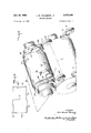
- FIG. 1 is a schematic representation of a folding machine constructed in accordance with the concept of my invention
- FIG. 2 is a schematic view of the folding machine of FIG. 1;
- FIG. 3 is an enlarged plan view of a record sleeve sheet or blank as it is received by my machine;
- FIG. 4 is an enlarged side elevation, partially in section, of the first and second roll, and the reversing and mating rolls as they appear during one phase of the machine cycle;
- FIG. 5 is a view similar to FIG. 4, but showing the rolls in a second operative phase of the machine cycle
- FIG. 6 is an enlarged perspective view of the first and second rolls, and the reversing and mating rolls;
- FIG. 7 is a perspective view showing the first and second rolls and the fold compressing rolls disposed adjacent thereto;
- FIG. 8 is an enlarged transverse section of the record sleeve blank subsequent to the main folding operation, but prior to the flap folding step;
- FIG. 9 is an enlarged perspective view of an envelope 012 record sleeve after passing through my folding mac me;
- FIG. 10 is an enlarged transverse sectional view taken along the line indicated at 1010 of FIG. 9;
- FIG. 11 is an enlarged section view taken along the line indicated at 11-11 of FIG. 9;
- FIG. 12 is a plan view of a different type of envelope blank which may be folded on my machine.
- FIG. 13 is a perspective view of the envelope of FIG. 12, subsequent to the folding operations.
- a succession of spaced blanks 10 are rapidly advanced into the machine between a pair of moving belts 12 which are mounted on rolls 14 provided for the purpose.
- the blanks 10 pass between a pair of feed rolls 16 which may serve merely to feed the blanks into the machine or they may be adapted to form various initial operations in a manner well known in the art, such as squaring the blanks with respect to their line of movement, cutting an elongated web of material into blank sizes, and applying glue to the margin of an envelope flap, for example.
- the blank 10 being processed is a record sleeve or holder, as best seen in FIGS. 9, l and 11.
- This sleeve comprises a front wall 18, a back wall 20, side flaps 22 and a center opening 24 through which the title of the record may be seen when a record is positioned in the sleeve.
- the open blank 10 of FIG. 3 passes between a first roll 26 and a coacting second roll 28.
- the top flap 18 first passes between rolls 26 and 28 and means are provided for adhering the first edge 30 thereof to the roll 26.
- This comprises a line of perforations or apertures 32 on the surface of the roll, FIGS. 4, and 6, which are in connection with an internal passage 34, FIGS. 4 and 5, that leads to a supply line 36.
- the supply line 36 provides a vacuum and a positive air pressure, depending upon the rotational position of the roll 26.
- the apertures 32 are provided with a vacuum force which picks up the first edge 30 and carries it around roll 26 until it reaches approximately its uppermost position, as seen in FIG. 4.
- the supply line 36 supplies a positive air pressure and the first edge 30 of the blank 10 is blown off the roll 26.
- a reversing roll 38 is disposed outwardly of each end of roll 26, these rolls being driven in a clockwise direction as shown by arrows 40, whereas roll 26 is driven in a counterclockwise direction as shown by the arrow 42. It is noted that the axis of roll 26 is parallel to the axis of rolls 38, but it is offset with respect thereto as seen in FIGS. 4 and 5.
- a mating roll 44 is provided for each reversing roll 38.
- This roll is mounted on a pivotal bracket indicated generally at 46 which pivots above line 48 for positioning the mating roll 44 between a remote position, out of engagement with reversing roll 38 as viewed in FIG. 4 to a second position wherein the mating roll 44 presses the front edge 30 of the sheet against its reversing roll 38 as viewed in FIG. 5.
- the bracket comprises a first arm 48 upon which the mating roll is rotatably mounted and a second arm 50 upon which a cam follower wheel 52 is mounted. Movement of the cam follower 52, and hence movement of the bracket 46 is initiated by the cam 54 which rotates in timed relationship with respect to the first roll 26.
- a spring 56 is mounted on arm 48 for resiliently urging roll 44 towards reversing roll 38, the tension being adjustable by means of screw 58 provided for the purpose.
- fold compressing rolls 60 are disposed adjacent the second roll 28 for urging the front wall 18 as Well as the back wall 20 into engagement with the second roll 28. It will be appreciated, as seen in FIGS. 4 and 5, that the roll 28 is provided with a line of perforations or apertures 62 which are connected via passage 64 to a source of vacuum. This serves to lead the sofolded blank 10 around the roll 28.
- a paste pot 66 is disposed adjacent roll 28, and rolls 68, 70 and 72 serve to transfer paste from the pot 66 to the flaps 22 of the blanks as they pass thereby while adhering to roll 28. It will be appreciated that a series of paste transfer rolls 68, 70 and 72 are disposed adjacent each edge of the blank so that paste is applied to both of the flaps 22.
- the blank 10 is transferred from roll 28 to roll 74, as seen in FIG. 1.
- a cutting roll 76 is disposed adjacent roll 74 for cutting the central opening 24, FIG. 9, in the blank 10.
- the blank ltl passes between the endless belts 78 and 80 mounted on rollers 82 which carries the sheet 10 through folding throats 84 which serve to fold over the flaps 20 from their positions as seen in FIG. 8 to their positions as seen in FIG. 10.
- the machine receives a blank 10 from feed rolls 16 and passes same between the first roll 26 and the second roll 28.
- the leading or front edge 30 is picked up by a vacuum force and is passed partially around roll 26.
- the vacuum force is released and positive air pressure is supplied to blow the leading edge 30 from roll 26.
- bracket 46 is pivoted due to the action of cam 54 to bring mating rolls 44 towards reversing rolls 38 to grip the front wall 18 therebetween and positively drive the leading portion of the blank back towards roll 28.
- the blank is folded along crease line 19 and vacuum appears at the opening 62 so that roll 28 retains the back wall 20 in engagement therewith.
- Compressing rolls 60 complete the folding operation, and the so-folded blank passes around roll 28 to the paste supplying station wherein paste is applied by means of roll 72 to the flaps 22. Then, the blank is transferred to roll 74 which carries it adjacent cutting roll 76 which cuts the central opening 24 therein. The last operation is to pass the blank through the folding throat 84 to fold over and secure flaps 212 to the front wall 18.
- the envelope 10 may take other forms such as envelope blank 10' having a front wall 18', a back wall 20', a crease line 19, side flaps 22 and a first edge 30'.
- the envelope 10' is fabricated in a manner similar to that described hereinbefore in connection with envelope 10, and hence like elements of the two envelopes are provided with the same numerals, except that in the later case they are primed. However. the step of cutting the central opening 24 in envelope 10 is omitted in envelope 10.
- a folding machine of the class described comprising a first roll and a co-acting second roll for receiving a sheet to be folded therebetween, said first roll having means for adhering a first edge of said sheet thereto for a portion of its revolution, a reversing roll axially spaced and having an opposite direction of rotation with respect to said first roll, a mating roll for said reversing roll, means mounting said mating roll for co-acting with said reversing roll to grip said first edge of the sheet therebetween during a portion of said reversing rolls revolution, whereby a sheet enters between said first and second rolls and the first edge passes partially around said first roll until said reversing roll and mating roll co-act to reverse the direction of movement of said first edge of the sheet, thereby folding said first edge or" the sheet in superimposed relationship with respect to the remainder of said sheet.
- a folding machine wherein there are a pair of reversing rolls, one being disposed at each end of said first roll, and a mating roll is provided for each reversing roll.
- a folding machine according to claim 1 wherein said means for adhering the first edge of said sheet to said first roll comprises apertures on the surface thereof. and a passage extending therethrough for connecting said apertures to a source of vacuum.
- a folding machine according to claim 1 wherein said means mounting said mating roll comprises a pivotal bracket for positioning said mating roll between a first remote position when said first edge of said sheet is adhering to said first roll and a second position for pressing said first edge of the sheet against said reversing roll.
- a folding machine further comprising a fold compressing roll mounted adjacent said second roll for compressing said sheet.
- a folding machine further comprising paste-applying rolls disposed adjacent said second roll for applying paste to the flaps of said sheet after said sheet has been folded in superimposed relationship.
- a folding machine wherein means are provided for connecting said apertures to a source of vacuum through said portion of a revolution when said first edge of said sheet is adhered to said first roll, and wherein means are provided for connecting said apertures to a source of positive air pressure through said portion of a revolution when said first edge is gripped between said reversing roll and mating roll.
- a folding machine wherein said pivotal bracket is centrally mounted and has a first arm extending in one direction upon which said mating roll is mounted, and has a second arm extending in a second direction, a cam follower mounted on said second arm for engagement with a cam surface directly driven with respect to said first roll.
- a folding machine further comprising folding throat means disposed adjacent said second roll for folding over the flaps of said sheet after the paste has been applied to the flaps.
- a folding machine according to claim 6 further comprising cutting means disposed adjacent said second roll for making a central opening in said sheet subsequent to the main folding operation.
- a folding machine according to claim 8 further comprising resilient means mounted on said first arm for resiliently urging said mating roll towards said reversing roll.
- a folding machine of the class described comprising a first roll and a co-acting second roll for receiving a sheet to be folded therebetween, said first roll having apertures on the surface thereof, and a passage extending therethrough for connecting said apertures a source of vacuum through a portion of a revolution when a first edge of said sheet is adhered to said first roll and wherein said passage is connected to a source of positive air pressure through a portion of a revolution wherein said first edge is driven in the opposite direction, a pair of reversing rolls, one being disposed on each end of said roll in axially spaced relationship with respect thereto, each of said reversing rolls having an opposite direction of rotation with respect to said first roll, a mating roll for each reversing roll, a pivotal bracket for each mating roll, each of said brackets having a first arm and a second arm, each mating roll being mounted on the first arm of its respective pivotal bracket for positioning said mating roll between a first remote position wherein said first end of said sheet is adh
Landscapes
- Folding Of Thin Sheet-Like Materials, Special Discharging Devices, And Others (AREA)
- Making Paper Articles (AREA)
Description
06h 1969 J. w. THOUSAND, JR 3,473,449
FOLDING MACHINE 5 Sheets-Sheet 1 Filed Aug. 14, 1967 INVENTOR.
Oct 1969 J. w. THOUSAND, JR 3,47
FOLDING MACHINE Filed Aug. 14, 1967 5 Sheets-Shes.
INVENTOR. do /y M4 UA/V 750mm),
Och 1969 J. w. THOUSAND, JR v 3,473,
FOLDING MACHINE Filed Aug. 14, 19s? INYENTOR. Jo y M404; mew,
Oct. 21, 1969 J. w. THOUSAND, JR 3,473,449
FOLDING MACHINE Filed Aug. 14, 1967 5 Sheets-Sheet i I N VEN TOR.
3,473,449 I GLDING MACHWE John William Thousand, 31"., Crestwood, Mo., assignor to St. Regis Paper Company, New York, N.Y., a corporation of New York Filed Aug. 14, 1957, Ser. No. 660,455
Int. Cl. B31b 21/26 US. Cl. 93-62 12 Claims ABSTRACT OF THE DISCLOSURE This invention relates to a new and improved machine for automatically folding sheets or blanks at high speeds. It is adapted, among other possible uses, for folding envelopes, such as record sleeves, for example.
Heretofore, sheets such as envelope blanks have been folded by passing the sheet between a pair of rolls with the front edge thereof being held against one of the rolls by vacuum means to pass it partially around the roll. Thence, the vacuum is released and the direction of movement of the front edge of the sheet is reversed, thereby folding said front edge in super-imposed relationship with respect to the remainder of the sheet. However, this has not been too satisfactory, especially when folding relatively large sheets at high speeds. The application and release of the vacuum is not positive enough so that every so often a sheet will not be folded properly. This, of course, means that the entire machine must be shut down and the defective blanks cleared therefrom, thereby causing additional labor as well as wasted production time. It is an object of my invention to overcome the difliculties encountered with such prior art devices.
In essence, the folding machine according to my invention includes a first and a second roll arranged to receive a sheet to be folded therebetween. The first roll is provided with means for adhering the first edge of the sheet thereto for a portion of its revolution. A reversing roll is disposed in axially based relationship with respect to said first roll and has an opposite direction of rotation with respect thereto. A mating roll is arranged to cooperate with said reversing roll to grip the first edge of the sheet therebetween during a portion of the reversing rolls revolution so that the sheet passes partially around said first roll until the reversing roll and mating roll co-act to reverse the direction of movement of the front edge, thereby folding that edge over in super-imposed relationship with respect to the remainder of the sheet.
As a feature of my invention, there may be a reversing roll and a mating roll disposed at each end of said first roll in order to provide a positive reversing action to the sheet. Another feature resides in the provision of apertures on the surface of said first roll which are connected to a vacuum source during the initial movement of the front edge of the sheet and which are connected to a source of positive air pressure to release the front edge of the sheet during its reversing movement, thereby increasing the elficiency of the reversing movement.
Another feature of my invention resides in the provision of a new and improved folding machine, which has means for mounting the mating rolls including a bracket pivotally mounted for positioning the mating roll between a first remote position to a second position nited States Patent Patented Oct. 21, 1969 wherein the mating roll presses the front edge of the sheet against its reversing roll. The bracket is pivoted by cam means which function in fixed relationship with respect to the first and second rolls. Further, resilient means are provided for urging the mating roll into engagement with its reversing roll for purposes of facilitating the gripping action of the sheet therebetween.
Still further according to my invention, I provide fold compressing rolls disposed adjacent the second roll to complete the sheet folding operation. Also, a paste-applying roll is disposed adjacent the second roll for applying paste to the flaps so that when the flaps are folded over by folding throat means disposed adjacent said paste applying roll, the flaps will be retained in their folded positions.
In one form of my invention means are provided adjacent the second roll for cutting a center opening through both the front wall and the back wall of a record sleeve envelope to provide a visual means for viewing the center of a record.
There has thus been outlined rather broadly the more important features of the invention in order that the detailed description thereof that follows may be better understood, and in order that the present contribution to the art may be better appreciated. There are, of course, additional features of the invention that will 'be described hereinafter which will form the subject of the claims appended hereto. Those skilled in the art will appreciate that the conception on which this disclosure is based may readily be utilized as the basis for the designing of other structures for carrying out the several purposes of the invention. It is important, therefore, that the claims be regarded as including such equivalent constructions as do not depart from the spirit and scope of the invention.
Several embodiments of the invention have been chosen for purposes of illustration and description, and are shown in the accompanying drawings, forming a part of the specification wherein:
FIG. 1 is a schematic representation of a folding machine constructed in accordance with the concept of my invention;
FIG. 2 is a schematic view of the folding machine of FIG. 1;
FIG. 3 is an enlarged plan view of a record sleeve sheet or blank as it is received by my machine;
FIG. 4 is an enlarged side elevation, partially in section, of the first and second roll, and the reversing and mating rolls as they appear during one phase of the machine cycle;
FIG. 5 is a view similar to FIG. 4, but showing the rolls in a second operative phase of the machine cycle;
FIG. 6 is an enlarged perspective view of the first and second rolls, and the reversing and mating rolls;
FIG. 7 is a perspective view showing the first and second rolls and the fold compressing rolls disposed adjacent thereto;
FIG. 8 is an enlarged transverse section of the record sleeve blank subsequent to the main folding operation, but prior to the flap folding step;
FIG. 9 is an enlarged perspective view of an envelope 012 record sleeve after passing through my folding mac me;
FIG. 10 is an enlarged transverse sectional view taken along the line indicated at 1010 of FIG. 9;
FIG. 11 is an enlarged section view taken along the line indicated at 11-11 of FIG. 9;
FIG. 12 is a plan view of a different type of envelope blank which may be folded on my machine; and
FIG. 13 is a perspective view of the envelope of FIG. 12, subsequent to the folding operations.
In the embodiment of the invention illustrated in FIGS. 1ll, a succession of spaced blanks 10 are rapidly advanced into the machine between a pair of moving belts 12 which are mounted on rolls 14 provided for the purpose. The blanks 10 pass between a pair of feed rolls 16 which may serve merely to feed the blanks into the machine or they may be adapted to form various initial operations in a manner well known in the art, such as squaring the blanks with respect to their line of movement, cutting an elongated web of material into blank sizes, and applying glue to the margin of an envelope flap, for example.
In the embodiment of FIGS. l-ll, the blank 10 being processed is a record sleeve or holder, as best seen in FIGS. 9, l and 11. This sleeve comprises a front wall 18, a back wall 20, side flaps 22 and a center opening 24 through which the title of the record may be seen when a record is positioned in the sleeve.
As best seen in FIGS. 1 and 2, the open blank 10 of FIG. 3 thence passes between a first roll 26 and a coacting second roll 28. The top flap 18 first passes between rolls 26 and 28 and means are provided for adhering the first edge 30 thereof to the roll 26. This comprises a line of perforations or apertures 32 on the surface of the roll, FIGS. 4, and 6, which are in connection with an internal passage 34, FIGS. 4 and 5, that leads to a supply line 36. Alternately, the supply line 36 provides a vacuum and a positive air pressure, depending upon the rotational position of the roll 26. When the first edge 30 of the blank passes through the nip between the rolls 26 and 28, the apertures 32 are provided with a vacuum force which picks up the first edge 30 and carries it around roll 26 until it reaches approximately its uppermost position, as seen in FIG. 4. At this point the supply line 36 supplies a positive air pressure and the first edge 30 of the blank 10 is blown off the roll 26.
As first seen in FIG. 6, a reversing roll 38 is disposed outwardly of each end of roll 26, these rolls being driven in a clockwise direction as shown by arrows 40, whereas roll 26 is driven in a counterclockwise direction as shown by the arrow 42. It is noted that the axis of roll 26 is parallel to the axis of rolls 38, but it is offset with respect thereto as seen in FIGS. 4 and 5.
Still referring to FIGS. 4, 5 and 6, a mating roll 44 is provided for each reversing roll 38. This roll is mounted on a pivotal bracket indicated generally at 46 which pivots above line 48 for positioning the mating roll 44 between a remote position, out of engagement with reversing roll 38 as viewed in FIG. 4 to a second position wherein the mating roll 44 presses the front edge 30 of the sheet against its reversing roll 38 as viewed in FIG. 5. The bracket comprises a first arm 48 upon which the mating roll is rotatably mounted and a second arm 50 upon which a cam follower wheel 52 is mounted. Movement of the cam follower 52, and hence movement of the bracket 46 is initiated by the cam 54 which rotates in timed relationship with respect to the first roll 26. Further, a spring 56 is mounted on arm 48 for resiliently urging roll 44 towards reversing roll 38, the tension being adjustable by means of screw 58 provided for the purpose.
As best seen in FIG. 7, fold compressing rolls 60 are disposed adjacent the second roll 28 for urging the front wall 18 as Well as the back wall 20 into engagement with the second roll 28. It will be appreciated, as seen in FIGS. 4 and 5, that the roll 28 is provided with a line of perforations or apertures 62 which are connected via passage 64 to a source of vacuum. This serves to lead the sofolded blank 10 around the roll 28.
Reverting to FIG. 1, a paste pot 66 is disposed adjacent roll 28, and rolls 68, 70 and 72 serve to transfer paste from the pot 66 to the flaps 22 of the blanks as they pass thereby while adhering to roll 28. It will be appreciated that a series of paste transfer rolls 68, 70 and 72 are disposed adjacent each edge of the blank so that paste is applied to both of the flaps 22.
Thereafter, the blank 10 is transferred from roll 28 to roll 74, as seen in FIG. 1. A cutting roll 76 is disposed adjacent roll 74 for cutting the central opening 24, FIG. 9, in the blank 10. Thence, the blank ltl passes between the endless belts 78 and 80 mounted on rollers 82 which carries the sheet 10 through folding throats 84 which serve to fold over the flaps 20 from their positions as seen in FIG. 8 to their positions as seen in FIG. 10.
In operation the machine receives a blank 10 from feed rolls 16 and passes same between the first roll 26 and the second roll 28. The leading or front edge 30 is picked up by a vacuum force and is passed partially around roll 26. Then, the vacuum force is released and positive air pressure is supplied to blow the leading edge 30 from roll 26. Simultaneously, bracket 46 is pivoted due to the action of cam 54 to bring mating rolls 44 towards reversing rolls 38 to grip the front wall 18 therebetween and positively drive the leading portion of the blank back towards roll 28. Also simultaneously, the blank is folded along crease line 19 and vacuum appears at the opening 62 so that roll 28 retains the back wall 20 in engagement therewith. Compressing rolls 60 complete the folding operation, and the so-folded blank passes around roll 28 to the paste supplying station wherein paste is applied by means of roll 72 to the flaps 22. Then, the blank is transferred to roll 74 which carries it adjacent cutting roll 76 which cuts the central opening 24 therein. The last operation is to pass the blank through the folding throat 84 to fold over and secure flaps 212 to the front wall 18.
As best seen in FIGS. 12 and 13, the envelope 10 may take other forms such as envelope blank 10' having a front wall 18', a back wall 20', a crease line 19, side flaps 22 and a first edge 30'. The envelope 10' is fabricated in a manner similar to that described hereinbefore in connection with envelope 10, and hence like elements of the two envelopes are provided with the same numerals, except that in the later case they are primed. However. the step of cutting the central opening 24 in envelope 10 is omitted in envelope 10.
Although certain particular embodiments of the invention are herein disclosed for purposes of explanation, further modification thereof, after study of this specification, will be apparent to those skilled in the art to which the invention pertains. Reerence accordingly should be had to the appended claims in determining the scope of the invention.
What is claimed and desired to be secured by Letters Patent is:
1. A folding machine of the class described, the combination comprising a first roll and a co-acting second roll for receiving a sheet to be folded therebetween, said first roll having means for adhering a first edge of said sheet thereto for a portion of its revolution, a reversing roll axially spaced and having an opposite direction of rotation with respect to said first roll, a mating roll for said reversing roll, means mounting said mating roll for co-acting with said reversing roll to grip said first edge of the sheet therebetween during a portion of said reversing rolls revolution, whereby a sheet enters between said first and second rolls and the first edge passes partially around said first roll until said reversing roll and mating roll co-act to reverse the direction of movement of said first edge of the sheet, thereby folding said first edge or" the sheet in superimposed relationship with respect to the remainder of said sheet.
2. A folding machine according to claim 1 wherein there are a pair of reversing rolls, one being disposed at each end of said first roll, and a mating roll is provided for each reversing roll.
3. A folding machine according to claim 1 wherein said means for adhering the first edge of said sheet to said first roll comprises apertures on the surface thereof. and a passage extending therethrough for connecting said apertures to a source of vacuum.
4. A folding machine according to claim 1 wherein said means mounting said mating roll comprises a pivotal bracket for positioning said mating roll between a first remote position when said first edge of said sheet is adhering to said first roll and a second position for pressing said first edge of the sheet against said reversing roll.
5. A folding machine according to claim 1 further comprising a fold compressing roll mounted adjacent said second roll for compressing said sheet.
6. A folding machine according to claim 1 further comprising paste-applying rolls disposed adjacent said second roll for applying paste to the flaps of said sheet after said sheet has been folded in superimposed relationship.
7. A folding machine according to claim 3 wherein means are provided for connecting said apertures to a source of vacuum through said portion of a revolution when said first edge of said sheet is adhered to said first roll, and wherein means are provided for connecting said apertures to a source of positive air pressure through said portion of a revolution when said first edge is gripped between said reversing roll and mating roll.
8. A folding machine according to claim 4 wherein said pivotal bracket is centrally mounted and has a first arm extending in one direction upon which said mating roll is mounted, and has a second arm extending in a second direction, a cam follower mounted on said second arm for engagement with a cam surface directly driven with respect to said first roll.
9. A folding machine according to claim 6 further comprising folding throat means disposed adjacent said second roll for folding over the flaps of said sheet after the paste has been applied to the flaps.
1%). A folding machine according to claim 6 further comprising cutting means disposed adjacent said second roll for making a central opening in said sheet subsequent to the main folding operation.
11. A folding machine according to claim 8 further comprising resilient means mounted on said first arm for resiliently urging said mating roll towards said reversing roll.
12. A folding machine of the class described, the combination comprising a first roll and a co-acting second roll for receiving a sheet to be folded therebetween, said first roll having apertures on the surface thereof, and a passage extending therethrough for connecting said apertures a source of vacuum through a portion of a revolution when a first edge of said sheet is adhered to said first roll and wherein said passage is connected to a source of positive air pressure through a portion of a revolution wherein said first edge is driven in the opposite direction, a pair of reversing rolls, one being disposed on each end of said roll in axially spaced relationship with respect thereto, each of said reversing rolls having an opposite direction of rotation with respect to said first roll, a mating roll for each reversing roll, a pivotal bracket for each mating roll, each of said brackets having a first arm and a second arm, each mating roll being mounted on the first arm of its respective pivotal bracket for positioning said mating roll between a first remote position wherein said first end of said sheet is adhering to said first roll and a second position for pressing said first edge of the sheet against said reversing roll, a cam directly driven with respect to said first roll, a cam follower being mounted on each of said second arms for engagement with said cams respectively, resilient means mounted on said first arms for resiliently urging said mating rolls towards said reversing rolls respectively, a fold compressing roll mounted adjacent said second roll for compressing said sheet therebetween, a pair of paste-applying rolls disposed adjacent said second roll for applying paste to the flaps of said sheet after said sheet has been folded in superimposed relationship, and folding throat means disposed adjacent said paste-applying rolls for folding over the flaps of said sheet after the paste has been applied thereto.
References Cited UNITED STATES PATENTS 3/1963 Polidori 9362 5/1967 Cohn 93-62
Applications Claiming Priority (1)
| Application Number | Priority Date | Filing Date | Title |
|---|---|---|---|
| US66045567A | 1967-08-14 | 1967-08-14 |
Publications (1)
| Publication Number | Publication Date |
|---|---|
| US3473449A true US3473449A (en) | 1969-10-21 |
Family
ID=24649606
Family Applications (1)
| Application Number | Title | Priority Date | Filing Date |
|---|---|---|---|
| US660455A Expired - Lifetime US3473449A (en) | 1967-08-14 | 1967-08-14 | Folding machine |
Country Status (1)
| Country | Link |
|---|---|
| US (1) | US3473449A (en) |
Cited By (4)
| Publication number | Priority date | Publication date | Assignee | Title |
|---|---|---|---|---|
| US3908524A (en) * | 1974-01-04 | 1975-09-30 | Shorewood Packaging Corp | Record jacket making machine |
| US4966353A (en) * | 1987-09-04 | 1990-10-30 | Mathias Bauerle Gmbh | Chief folding machine with eye adhesive moistener |
| US5899447A (en) * | 1997-09-02 | 1999-05-04 | The Procter & Gamble Company | Apparatus for stacking pop-up towels |
| US20160113235A1 (en) * | 2014-10-27 | 2016-04-28 | Jiangsu Zhongheng Pet Articles Joint-Stock Co., Ltd. | Folding pet urine pad convenient to take as well as production method and processing equipment thereof |
Citations (2)
| Publication number | Priority date | Publication date | Assignee | Title |
|---|---|---|---|---|
| US3079847A (en) * | 1962-05-28 | 1963-03-05 | Commercial Envelope Mfg Co Inc | Blank folding and gluing device |
| US3316819A (en) * | 1964-09-17 | 1967-05-02 | Champion Paper Inc | Envelope machine |
-
1967
- 1967-08-14 US US660455A patent/US3473449A/en not_active Expired - Lifetime
Patent Citations (2)
| Publication number | Priority date | Publication date | Assignee | Title |
|---|---|---|---|---|
| US3079847A (en) * | 1962-05-28 | 1963-03-05 | Commercial Envelope Mfg Co Inc | Blank folding and gluing device |
| US3316819A (en) * | 1964-09-17 | 1967-05-02 | Champion Paper Inc | Envelope machine |
Cited By (4)
| Publication number | Priority date | Publication date | Assignee | Title |
|---|---|---|---|---|
| US3908524A (en) * | 1974-01-04 | 1975-09-30 | Shorewood Packaging Corp | Record jacket making machine |
| US4966353A (en) * | 1987-09-04 | 1990-10-30 | Mathias Bauerle Gmbh | Chief folding machine with eye adhesive moistener |
| US5899447A (en) * | 1997-09-02 | 1999-05-04 | The Procter & Gamble Company | Apparatus for stacking pop-up towels |
| US20160113235A1 (en) * | 2014-10-27 | 2016-04-28 | Jiangsu Zhongheng Pet Articles Joint-Stock Co., Ltd. | Folding pet urine pad convenient to take as well as production method and processing equipment thereof |
Similar Documents
| Publication | Publication Date | Title |
|---|---|---|
| US2851934A (en) | Manufacture of envelopes | |
| US2811905A (en) | Envelope manufacture | |
| US3069982A (en) | Manufacture of quick-opening envelopes or bags | |
| US3473449A (en) | Folding machine | |
| US2244723A (en) | Envelope machine | |
| US6305600B1 (en) | Carton having a prefolded interior paper lining and a method of preparing a carton with a prefolded interior paper lining | |
| US3733982A (en) | Machine for producing self-opening envelopes | |
| US5176611A (en) | Sealing assembly attachment and method | |
| US2126920A (en) | Bag making machine | |
| US3166996A (en) | Envelope making machine | |
| US2325042A (en) | Method and apparatus for bottoming bags | |
| US2895387A (en) | Multiply bag with supplemental sleeve | |
| US1713243A (en) | Flap-turning mechanism | |
| US2354825A (en) | Means and method for decurling envelope flaps | |
| US2800841A (en) | Envelope processing machine | |
| US1827539A (en) | Making envelopes and machine therefor | |
| US2098970A (en) | Envelope machine | |
| US3316819A (en) | Envelope machine | |
| US692695A (en) | Bag-making machine. | |
| US1690626A (en) | Machine for forming bag bottoms in bag tubes | |
| US2364551A (en) | Paper bag machine | |
| US534313A (en) | connors | |
| US616605A (en) | crist | |
| US3172342A (en) | Bag-making machines | |
| US2044476A (en) | Apparatus for making bags |